


Freescale Semiconductor Document Number: AN4292
Application Note Rev 0, 10/2012
DEMOMMA8491 Xtrinsic Accelerometer Evaluation Kit
by: FengYi Li
Applications Engineer
This application note provides an overview of the
Xtrinsic DEMOMMA8491 kit and its evaluation
guidelines.
The DEMOMMA8491 kit contains two boards:
• Demo board: provides a tamper detection sensor
demonstration using the Xtrinsic MMA8491Q
45° tilt sensor and 3-axis accelerometer, housed
in a transparent plastic case.
• Breakout board: provides easy access to every
pin of the QFN sensor for evaluation.
This document describes board functionality and
features, how to use these boards, and what to look for
when evaluating the devices. The last section provides
reference schematics and the bills of materials.
Contents
1 DEMOMMA8491 Demo Board . . . . . . . . . . . . . . . . . . . . 2
1.1 Acceleration directions . . . . . . . . . . . . . . . . . . . . . . 2
1.2 Using the demo board . . . . . . . . . . . . . . . . . . . . . . . 2
1.3 Acceleration values are cumulative. . . . . . . . . . . . . 3
2 DEMOMMA8491 Breakout Board . . . . . . . . . . . . . . . . . . 4
2.1 Pin map . . . . . . . . . . . . . . . . . . . . . . . . . . . . . . . . . . 4
2.2 Suggested application connections . . . . . . . . . . . . . 5
2.3 Soldering considerations . . . . . . . . . . . . . . . . . . . . . 5
2.4 Evaluating performance. . . . . . . . . . . . . . . . . . . . . . 6
3 Schematics and Bill of Materials (BOM) . . . . . . . . . . . . . 6
3.1 Demo board schematic . . . . . . . . . . . . . . . . . . . . . . 6
3.2 Demo board BOM . . . . . . . . . . . . . . . . . . . . . . . . . . 6
3.3 Breakout board schematic. . . . . . . . . . . . . . . . . . . . 7
3.4 Breakout board BOM . . . . . . . . . . . . . . . . . . . . . . . . 7
4 Revision History. . . . . . . . . . . . . . . . . . . . . . . . . . . . . . . . 8
© 2012 Freescale Semiconductor, Inc. All rights reserved.
1 DEMOMMA8491 Demo Board
The demo board of the DEMOMMA8491 kit is an out-of-the-box 3-axis MEMS tilt sensor. It showcases
a simple tilt sensor implemented with the MMA8491Q device, with 10 additional passive components.
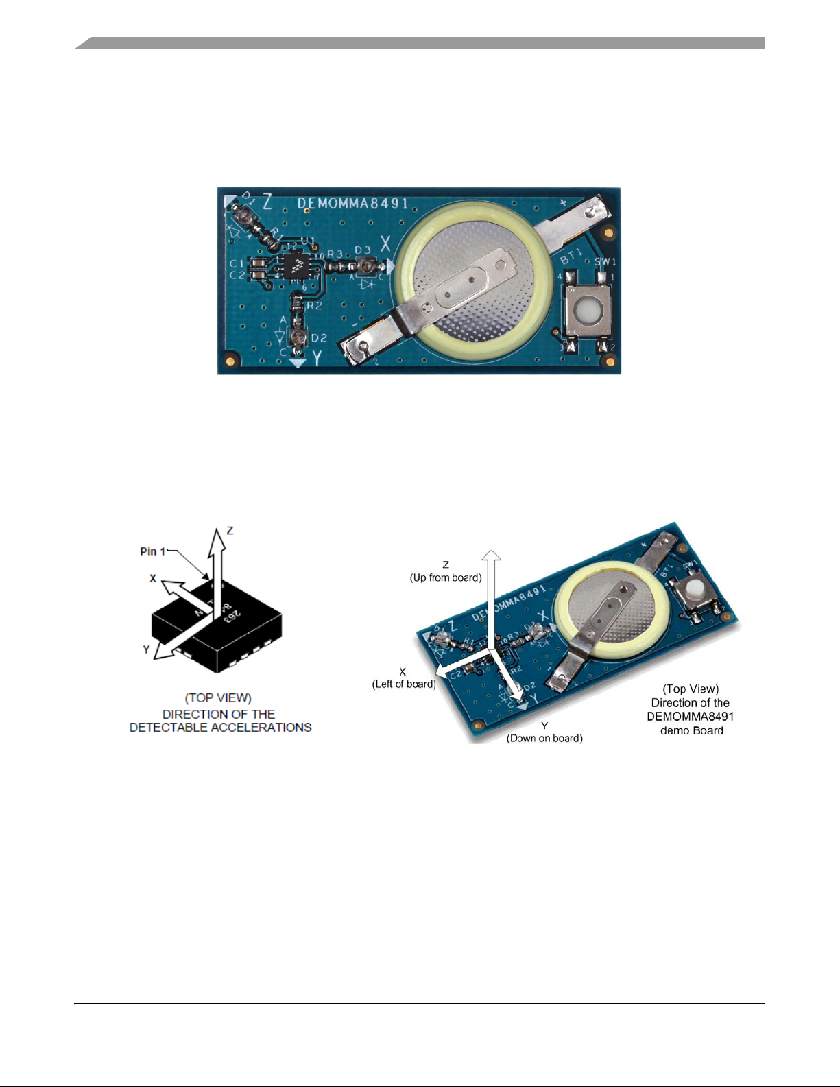
Figure 1. DEMMMA8491 demo board
1.1 Acceleration directions
The demo board uses the acceleration directions in Figure 2. The left image shows the acceleration
direction on the MMA8491Q device. The right image shows the acceleration direction of the demo board.
Figure 2. Sensor orientation
1.2 Using the demo board
The demo is powered by a 3V coin battery and is controlled by one switch button (SW1). When the switch
is pressed, the tilt sensor is powered on, and it takes one sample of the current acceleration. The tilt
detection result is simultaneously displayed with 3 LEDs (each LED is paired with one of the X, Y, Z axes).
A lit LED indicates that a tilt angle greater than or equal to 45° is detected on that axis.
DEMOMMA8491 Xtrinsic Accelerometer Evaluation Kit, Rev 0
2 Freescale Semiconductor, Inc.
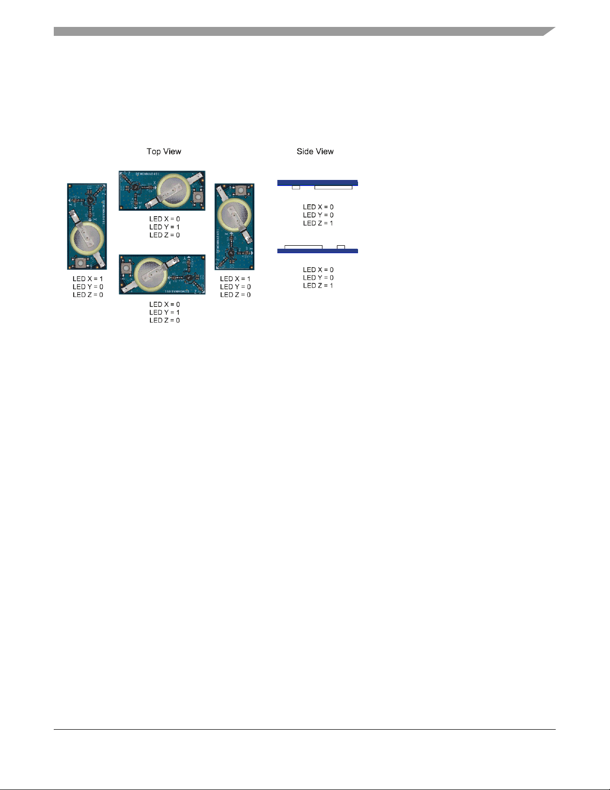
To demonstrate the kit, hold the demo board to the desired position, then press and hold down the switch
• LED X = 0 indicates that LED X
is turned off.
• LED X = 1 indicates that LED X
is turned on.
button. Make sure that your hand is steady. Observe the LEDs for a tilt report. Release the button to discard
the sample.
Figure 3 shows the LED status at 6 different orientations.
Figure 3. LED states for different orientations
1.3 Acceleration values are cumulative
The MMA8491Q device is a MEMS-based accelerometer. It picks up the acceleration signal (if it is
present), and compares the acceleration to an internal threshold of 0.688g. When the demo board is held
at a 45° angle, the acceleration reading along that axis (coming from the earth gravity) is about 0.688g. In
this case, that axis's output (XOUT, YOUT or ZOUT) is triggered to logic high.
When you provide external acceleration (other than the earth gravity) on the demo board, the tilt sensor
reports the cumulative acceleration. As the result of these additional g-forces, you might observe positive
tilt detection when the board is at a position less than a 45°angle.
DEMOMMA8491 Xtrinsic Accelerometer Evaluation Kit, Rev 0
Freescale Semiconductor, Inc. 3

2 DEMOMMA8491 Breakout Board
J1-1
J1-2
J1-3
J3-1
J3-2
J3-3
J2-1 J2-2 J2-3
For evaluating the MMA8491Q industrial 12-pin QFN tilt sensor, the breakout board provides practical
and efficient access, with minimum soldering work.
Figure 4. Breakout board
The DEMOMMA8491 breakout board has fanned out all of the MMA8491Q pins, except the bypass pin
(BYP). It has three top-layer components: the MMA8491Q device and two 0.1 uF ceramic capacitors (C1,
C2). The board itself is a two-layer PCB, using a 0.1 inch pitch between the breakout pins.
The device should have a 0.1 uF capacitor connected between the bypass pin (BYP) and ground. This
requirement is satisfied with the capacitor C1. The device also needs a high frequency filter capacitor on
VDD. This requirement is satisfied with the capacitor C2. These recommendations are listed in the
MMA8491Q data sheet.
2.1 Pin map
Table 1 maps the pins of the breakout board to the MMA8491Q device pins.
Table 1. Breakout board to MMA8491Q sensor pins
Breakout
Board
Pin Name Pin Name
J1-1 VDD 2 Vdd Supply Voltage Input
J1-2 EN 4 En Enable Accelerometer on logic 1 Input
J1-3 GND 7 Gnd Ground plate Ground
J2-1 SDA 4 SDA I
J2-2 SCL 5 SCL I
MMA8491Q
Device
Description Pin Status
2
C bus data Ground
2
C bus clock Input
J2-3 GND 6 Gnd Ground Input / Output
J3-1 ZOUT 8 Zout Tri-state Z-Axis tilt detect output Output
DEMOMMA8491 Xtrinsic Accelerometer Evaluation Kit, Rev 0
4 Freescale Semiconductor, Inc.
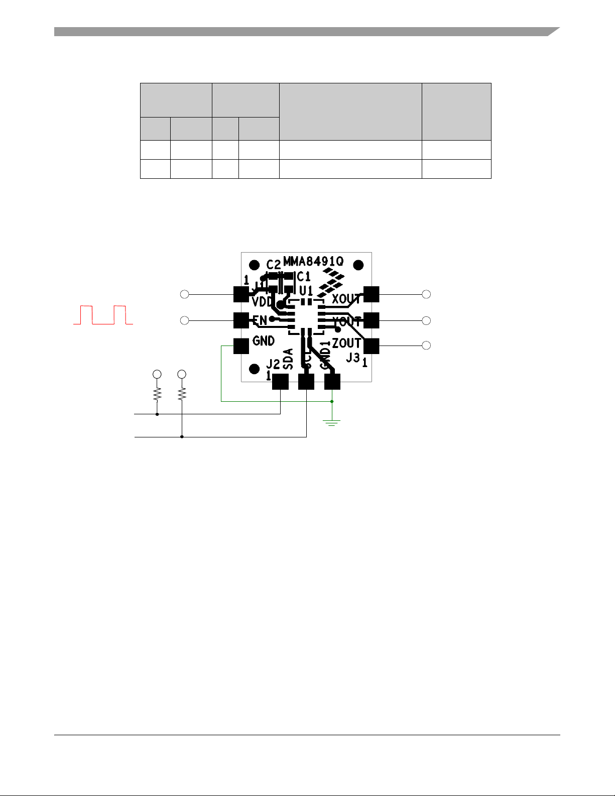
Table 1. Breakout board to MMA8491Q sensor pins (Continued)
Xout
Yout
Zout
V
DD
EN
Pulsed EN signal
SDA
V
DD
SCL
V
DD
4.7kΩ
4.7kΩ
Breakout
Board
Pin Name Pin Name
J3-2 YOUT 9 Yout Tri-state Y-Axis tilt detect output Output
J3-3 XOUT 10 Xout Tri-state X-Axis tilt detect output Output
MMA8491Q
Device
Description Pin Status
2.2 Suggested application connections
To ensure that the accelerometer is fully functional, connect the breakout board as shown in Figure 5.
This connection follows the recommendations listed in MMA8491Q data sheet.
• The power supply decoupling capacitor is placed as close as possible to the VDD pin. The 0.1 μF
• When the I2C communication line is used, pullup resistors (one pullup resistor for each line) should
2.3 Soldering considerations
The breakout board is a top component two-layer PCB board, with device pins fanned out to 0.1 inch pitch
copper pads. There is no special soldering handling requirement when using the breakout board—you can
directly hand-solder wires to it.
For more information about the standard MMA8491Q device mounting process, see the MMA8491Q data
sheet.
Figure 5. Example application with I2C bus engaged
capacitor value has been chosen to minimize the average current consumption, while still
maintaining an acceptable level of power supply high-frequency filtering.
be used to connect to SDA and SCL. If the SDA/SCL pins are not used, then they should be tied
to ground. It is recommended that you use resistors no less than 1KΩ, to reduce the current load on
the I2C bus.
DEMOMMA8491 Xtrinsic Accelerometer Evaluation Kit, Rev 0
Freescale Semiconductor, Inc. 5

2.4 Evaluating performance
When evaluating the MMA8491Q tilt sensor performance using the breakout board, consider offset
factors:
• Offset variation over temperature
• Board mount offset
• Breakout-board-to-system alignment
For offset variation and board mount offset data, see the MMA81941Q data sheet.
We suggest that you perform a breakout-board-to-system alignment check. Typically, the tilt sensor axes
may not exactly align with the axes of the customer's system. This misalignment translates to the cross-axis
offset, effectively changing the tilt detection angle. A system adjustment helps to get a more accurate
evaluation result. You can use the readouts from the MMA8491Q device via I2C bus for a coarse alignment
check, without having to use a reference accelerometer.
3 Schematics and Bill of Materials (BOM)
3.1 Demo board schematic
Figure 6. Demo board schematic
3.2 Demo board BOM
Table 2. Demo board BOM
Item Quantity Reference Value Description
1 1 BT1 CR2016-F2N Battery, lithium coin, 3V 90MAH 20MM PCB SMT
2 2 C1, C2 GRM188R71H104KA93D Capacitor, ceramic, 0.1UF 50V 10% X7R 0603
3 3 D1, D2, D3 HLMP-Q156-H0011 LED, RED SGL 50MA SMT
4 3 R1, R2, R3 RK73H1JTTD6800F Resistor, MF 680 OHM 1/10W 1% 0603
DEMOMMA8491 Xtrinsic Accelerometer Evaluation Kit, Rev 0
6 Freescale Semiconductor, Inc.

Table 2. Demo board BOM (Continued)
Item Quantity Reference Value Description
5 1 SW1 EVQQ2B03W Switch SPST, PB NO 0.5N 20MA 15V SMT
6 1 U1 MMA8491Q IC, 3-axis low voltage tilt sensor 1.95–3.6V QFN12
3.3 Breakout board schematic
Figure 7. Breakout board schematic
3.4 Breakout board BOM
Table 3. Breakout board BOM
Item Quantity Reference Value Description
1 1 U1 MMA8491Q IC, 3-axis low voltage tilt sensor 1.95–3.6V QFN12
2 2 C1,C2 GRM188R71H104KA93D Capacitor, ceramic, 0.1UF 50V 10% X7R 0603
DEMOMMA8491 Xtrinsic Accelerometer Evaluation Kit, Rev 0
Freescale Semiconductor, Inc. 7

4Revision History
Revision 0 is the initial release of this document.
DEMOMMA8491 Xtrinsic Accelerometer Evaluation Kit, Rev 0
8 Freescale Semiconductor, Inc.

How to Reach Us:
Home Page:
freescale.com
Web Support:
freescale.com/support
Information in this document is provided solely to enable system and software
implementers to use Freescale products. There are no express or implied copyright
licenses granted hereunder to design or fabricate any integrated circuits based on the
information in this document.
Freescale reserves the right to make changes without further notice to any products
herein. Freescale makes no warranty, representation, or guarantee regarding the
suitability of its products for any particular purpose, nor does Freescale assume any
liability arising out of the application or use of any product or circuit, and specifically
disclaims any and all liability, including without limitation consequential or incidental
damages. “Typical” parameters that may be provided in Freescale data sheets and/or
specifications can and do vary in different applications, and actual performance may
vary over time. All operating parameters, including “typicals,” must be validated for each
customer application by customer’s technical experts. Freescale does not convey any
license under its patent rights nor the rights of others. Freescale sells products pursuant
to standard terms and conditions of sale, which can be found at the following address:
freescale.com/salestermsandconditions.
Freescale, the Freescale logo, AltiVec, C-5, CodeTest, CodeWarrior, ColdFire, C-Ware,
Energy Efficient Solutions logo, Kinetis, mobileGT, PowerQUICC, Processor Expert,
QorIQ, Qorivva, StarCore, Symphony, and VortiQa are trademarks of Freescale
Semiconductor, Inc., Reg. U.S. Pat. & Tm. Off. Airfast, BeeKit, BeeStack, ColdFire+,
CoreNet, Flexis, MagniV, MXC, Platform in a Package, QorIQ Qonverge, QUICC
Engine, Ready Play, SafeAssure, SMARTMOS, TurboLink, Vybrid, and Xtrinsic are
trademarks of Freescale Semiconductor, Inc. All other product or service names are
the property of their respective owners.
© 2012 Freescale Semiconductor, Inc.
Document Number: AN4292
Rev 0
10/2012
 Loading...