

DEMO9S08QE32—Quick Start Guide
Ultra-Low-Power 8-bit Microcontroller
DEMO9S08QE32
Taking the Lead
in Low Power
• Quick Start Guide
• Lab Tutorials
®
• CodeWarrior
• Getting Started DVD
Manual
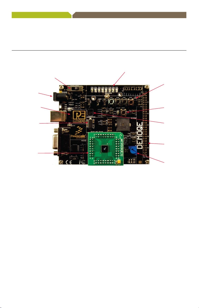
Get to Know the
DEMO9S08QE32 Board
Barrel
connector for
external power
32.768k Crystal
DC9S08QE32
Daughter Card
Figure 1. DEMOQE baseboard with DC9S08QE32 daughter card.
Power select
Jumper (USB or
external)
LEDs
Push Button
RESET ButtonEmbedded BDM
MMA7260
Accelerometer
MCU Port
Potentiometer

DEMO9S08QE32—Quick Start Guide
Introduction
DEMO9S08QE32 is a cost-effective board
targeting quick microcontroller evaluation.
The board includes a DEMOQE baseboard and
a DC9S08QE32 daughter card. In combination,
they can be used to highlight the key features
on the MC9S08QE32 device. The board also
includes a power terminal to measure the ultra-
low power consumption of the MC9S08QE32
device.
This quick start guide is designed to get
you ready to develop your application on
the QE32 within minutes. Please take a look
at the DEMO9S08QE32 Labs document
(DEMO9S08QE32LAB) to learn more about the
key benefits that QE32 gives your application.

Step-by-Step Installation Instructions
Accelerometer
Demo Application
This graphing application will graph
data from the serial port or virtual
serial port on the DEMOQE board.
The state of the on-board threeaxis accelerometer is sampled by
the microcontroller-based serial
accelerometer
code using on-chip A/D converter
channels. This data is converted
into ASCII characters and sent
out the serial port of the
board. The data is then graphed by
the
PC-based graphing application
for the user to
may be used to graph any data
as long as the data is formatted
properly.
Both the MCU-based
demonstration code and the
PC-based graphing application
may be downloaded from
www.pemicro.com/fixedlinks/
demoQEtoolkit.html.
Virtual Serial Port
The DEMO9S08QE32 board also
has the capability
a virtual serial port
This allows the PC to send and
receive serial data
communication pins of P&E’s
Embedded Multilink design.
Using jumpers J6 and J7, this
virtual serial port may be configured
to connect to the SCI port on the
QE32 processor.
demonstration
DEMOQE
view. This application
of implementing
on the PC.
via the serial
STEP
1
Install CodeWarrior®
for Microcontrollers
CodeWarrior is a powerful tool designed to help
you maximize your time to market. CodeWarrior
installation is a one-time required step before
connecting the board to your computer.
1. Insert provided DVD into computer
and a menu will appear.
2. Click on the appropriate board and
“Install CodeWarrior.”
3. Follow the on-screen instructions until
installation is complete.
Once installation is complete, take advantage of
several CodeWarrior tutorials that will walk you
through various development tool features, such
as “C Programming,” “Assembly Programming,”
“Using Processor Expert” and more. Simply
open CodeWarrior via the “Programs
CodeWarrior
> CW for Microcontroller V6.x >
CodeWarrior IDE.exe” path. Click “Run Getting
Started Tutorial” from the startup dialog, select a
tutorial and follow the on-screen instructions.
> Freescale

DEMO9S08QE32—Quick Start Guide
STEP
2
Install DEMOQE Toolkit
DEMOQE Toolkit install is a one-time required
step. The DEMOQE Toolkit includes graphical
utilities that run on your computer and help
speed up your development. These utilities
take development beyond the hardware and
interact with the target microcontroller over
the same USB multilink reference design on
the board that allows you to debug using
CodeWarrior. Best of all, you can debug
your microcontroller in CodeWarrior while
simultaneously using one of the following
utilities: Logic Analyzer, Serial Grapher,
Terminal Window and Accelerometer
Demo Grapher.
1. Insert provided Gettting Started DVD into
computer and a menu will appear.
2. Click on “DEMO9S08QE32,” then click on
“Install DEMOQE Toolkit.” This will launch the
P&E DEMOQE Toolkit Installer.
3. Follow the on-screen instructions to
complete installation.
For more information on DEMOQE
Toolkit, read the board user manual
(DEMO9S08QE32UM.pdf) included in
the DVD under “DEMO9S08QE32 >
DEMO9S08QE32 User Manual.”
For new and upgraded utilities to
“DEMOQE Toolkit,” visit www.pemicro.com/
fixedlinks/demoQEtoolkit.html.
Additional DEMOQE
Toolkit Applications
In addition to the Quick Start
Application and Logic Analyzer
Utility, the DEMOQE Resources
on the Getting Started DVDROM features other toolkit
applications which work with the
DEMO9S08QE32 board.
•AccelerometerDemo
•LogicAnalyzer
•SerialGrapher
•TerminalWindow
•UnsecureUtility

STEP
3
Connect Board to Computer
USB driver installation is a one-time required
step that requires CodeWarrior installation first.
1. Remove board from anti-static pouch.
The green 8-bit MC9S08QE32 daughter card
will be mounted on the base board.
2. Connect provided USB cable from a
free USB port on your computer to the
USB connector on the board.
3. Operating system will recognize your board
as new hardware and will prompt you to
install the USB drivers. Choose recommended
option to install the software automatically.
USB drivers for your board were pre-loaded in
CodeWarrior installation.
4. Follow on-screen instructions until all USB
driver installations are complete. The green
USB LED on-board should illuminate.
STEP
4
Test Board by Running
Quick Start Application
Now that you have successfully completed
the software and hardware setup, test your
board by running the Quick Start Application
pre-loaded in the microcontroller’s on-chip
flash memory.
The programmed application samples the
microcontroller’s general-purpose input pins
connected to push buttons to perform two
actions. The first action is to illuminate
Accelerometer Demo
LED with a general-purpose output pin.
The second action is to play a tone per push
button on the speaker using a pulse-width
modulated signal programmed at different
frequencies. Last, the application samples
the potentiometer using the microcontroller’s
analog-to-digital converter and uses the
result to vary the light intensity of an LED
by changing their pulse-width modulated
signal’s duty cycle.
1.
Turn the SYSTEM POWER switch to the
ON position. The red POWER LED will illuminate
and application will start.
2. Press push buttons labeled PTA2, PTA3. A tone
will be emitted from speaker when each push
button is pressed, and the LED labeled PTC0
will illuminate, while LEDs labeled PTC[2:3]
and PTC[4:5] turn off respectively.
3. Rotate potentiometer to vary light intensity
of the LED labeled PTC1.
4. Now that your board is functional, try out the
provided labs in the DEMO9S08QE32 Labs
document to learn more about the ultra-low
power MC9S08QE32 microcontroller and
other features included with your board.

Learn More:
Freescale and the Freescale logo are trademarks or registered
trademarks o f Freescale Semiconductor, Inc. in the U.S. and other
countries. A ll other product or service names are the property of their
respective owners. © Freescale Semiconductor, Inc. 2008.
Doc Number: DEMO9S08QE32QSG / REV 0
Agile Number: 926-24596 / REV A
For more information about
Freescale products, please visit
www.freescale.com/lowpower.
 Loading...