


DEMO9S08JS16—Quick Start Guide
8-bit HCS08 Embedded Controllers
DEMO9S08JS16
Entry-level USB MCU designed
for affordable PC peripherals
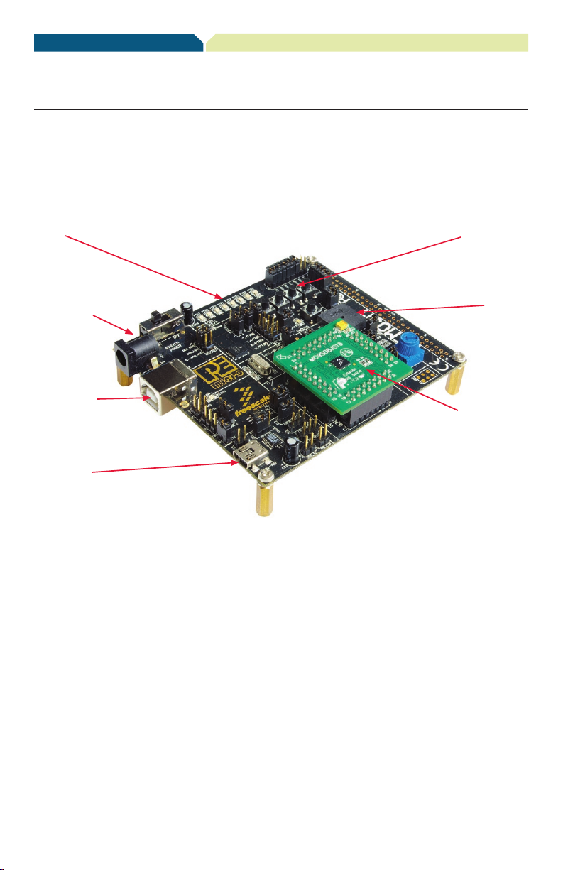
Get to Know the DEMO9S08JS16 Board
LEDs
External Power
Connector
PEmicro
Embedded
Multilink USB
Connector
Mini-AB USB
Conector
Push Buttons
Speaker
DC9S08JS16
Daughter Card
Figure 1. DEMOJM baseboard with DC9S08JS16 daughter card

DEMO9S08JS16—Quick Start Guide
DEMO9S08JS16—Quick Start Guide
Introduction
DEMO9S08JS16, with a DEMOJM baseboard and
a DC9S08JS16 daughter card, is a cost-effective
kit targeting quick MC9S08JS16 evaluation.
It can be used to demonstrate the features
of the MC9S08JS16 device, starting with the
on-chip USB 2.0 full-speed device controller
and transceiver. The USB features are supported
in hardware through a dedicated USB mini-AB
connector and in software through the included
complimentary USB stack.
This quick start guide is designed to get you
ready to develop your next USB application using
the MC9S08JS16 within minutes. Please take
a look at the DEMO9S08JS16 Labs document
(DEMO9S08JS16LAB) included in the “Training”
section of the DVD to learn more about the key
USB benefits that JS16 gives your application.

Step-by-Step Installation Instructions
USB Bootloader
A comprehensive USB bootloader
solution is provided for MC9S08JS16.
The boot ROM holds the code for
upgrading the firmware in flash
via USB interface. Freescale
provides a friendly PC GUI that can
communicate with the bootloader in
ROM. The PC GUI works with the
code in boot ROM to complete the
firmware update. The update process
is quick and reliable.
USB-MINI stack
Freescale provides a comprehensive
USB software solution through a
complimentary USB stack. The
Freescale USB-MINI stack enables
USB device modes of operation.
The USB stack supports several
HID and CDC to UART projects. The
complimentary stack also interfaces
with CodeWarrior™ Development
Studio, providing a productive,
comprehensive development
environment for designing embedded
applications. environment for
designing embedded applications.
Virtual Serial Port
The DEMO9S08JS16 board has
the capability to implement a virtual
serial port on the PC, allowing the
PC to send and receive serial data
via the USB and SCI interfaces
of MC9S08JS16. Using jumper
J4, this virtual serial port may be
configured to connect to the serial
port of P&E Embedded Multilink.
STEP
1
Install CodeWarrior
Development Studio
for Microcontrollers
CodeWarrior is a powerful tool designed to help
you minimize your time to market. CodeWarrior
Service Pack will install the appropriate support
files for the MC9S08JS16 to the existing
CodeWarrior installation. CodeWarrior
installation is a one-time required step before
connecting the board to your computer.
1. Insert the provided DVD into the computer.
A menu will appear.
2. Select the appropriate board and click “Install
CodeWarrior.”
3. Follow the on-screen instructions until
installation is complete.
Once the installation is complete, you can
take advantage of several CodeWarrior
tutorials that will walk you through various
development tool features, such as “C
Programming,” “Assembly Programming,”
“Using Processor Expert™” and more.
Simply open CodeWarrior using the path
“Programs>Freescale CodeWarrior>CW for
Microcontroller V6.x>CodeWarrior IDE.exe.”
Click “Run Getting Started Tutorial” from the
startup dialog, select a tutorial and follow the
on-screen instructions.
STEP
2
Install CodeWarrior for
Microcontroller 6.2.1 Patch and
MC9S08JS16 Service Pack
To make the CodeWarrior capable of creating
and compiling the MC9S08JS16 project, the
CodeWarrior 6.2.1 patch and JS16 service
pack need to be installed. The CodeWarrior
6.2.1 patch and JS16 service pack installation
are a one-time required step before
connecting the board to your computer.

DEMO9S08JS16—Quick Start Guide
DEMO9S08JS16—Quick Start Guide
STEP
4
1. Insert the provided DVD into the computer.
A menu will appear.
2. Select the appropriate board and click “Install
CodeWarrior Development Studio
for Microcontroller 6.2.1 patch.”
3. Follow the on-screen instructions until
installation is complete.
4. Select the appropriate board and click “Install
MS9S08JS16 Service Pack”
5. Follow the on-screen instructions util installation
is complete.
After the CodeWarrior 6.2.1 patch and JS16
service pack are installed, the MC9S08JS16
silicon can be selected when creating the
application, and the JS16 project can be
compiled correctly.
STEP
3
Install Bootloader GUI
MC9S08JS16 supports a USB bootloader.
The user’s application code can be downloaded
(updated) using the USB bootloader or BDM
debug port. If the USB bootloader is adopted,
a friendly PC GUI must be installed. This GUI
works with the USB bootloader located in boot
ROM to transfer and program the firmware
(s19 code) to MC9S08JS16’s flash memory.
The installation of a PC GUI is a one-time step
before the USB bootloader is used.
1. Insert the provided DVD into the computer. A menu
will appear.
2. Select the appropriate board and click on “Install
Bootloader GUI.”
3. Follow the on-screen instructions until installation
is complete.
The CodeWarrior compiles and links the
MC9S08JS16 project to generate the s19
code. The s19 code can be selected by the
bootloader GUI and programmed to the
MC9S08JS16 flash. For more information
about USB bootloader, please refer to
“MC9S08JS16 USB bootloader GUI user
guide” in the DEMO9S08JS16 DVD.
Install DEMO Code
(based on USB-MINI stack)
for MC9S08JS16
Freescale USB-MINI stack for MC9S08JS16
is a complimentary stack with the appropriate
JS16 USB Device mode low-level drivers
and top-level HID class and CDC class
examples. To exercise the various USB
examples packaged with the stack, follow
the step-by-step DEMO9S08JS16 Labs
document (DEMO9S08JS16LAB) included
in the “Training” section of the DVD. Stack
installation is a one-time required step before
developing applications with this software.
1. Insert the provided DVD into the computer. A menu
will appear.
2. Click “Install JS16 USB Demo.” This will launch
the stack installer.
3. Follow on-screen instructions until installation
is complete.
STEP
5
Install PEmicro
Demo Board Toolkit
PEmicro Embedded Multilink Toolkit
includes graphical utilities that run on your
computer and help speed up your application
development. These utilities take development
beyond the hardware and interact with the
target microcontroller over the same USB
multilink reference design on the board that
allows you to debug using CodeWarrior. Best
of all, you can debug your microcontroller
in CodeWarrior while simultaneously using
one of the following utilities: Logic Analyzer,
Serial Grapher and Terminal Window. PEmicro
Embedded Multilink Toolkit installation is a
one-time required step.

STEP
7
1. Insert the provided DVD into the computer. A menu
will appear.
2. Click “Install PEmicro Toolkit.” This will launch the
toolkit installer.
3. Follow the on-screen instructions to complete the
installation.
For more information on the PEmicro Embedded
Multilink Toolkit read the DEMO9S08JS16
User Manual (DEMO9S08JS16 UM.pdf) included
in the “Documentation” section of the DVD.
For new and upgraded utilities to the
PEmicro Embedded Multilink Toolkit,
visit www.pemicro.com.
STEP
6
Connect Board to Computer
USB driver installation is a one-time required
step, to be completed after CodeWarrior
installation.
1. Remove DEMOJM baseboard and
DC9S08JS16 daughter card from
anti-static bags.
2. Plug in the MC9S08JS16 daughter card to
DEMOJM baseboard, aligning pin 1 arrows.
3. Connect the provided A to B gray USB cable
from a free USB port on your computer to
the USB connector on the board.
4. The operating system will recognize your
board as new hardware and will prompt you
to install the USB drivers. Choose the
recommended option to install the software
automatically. USB drivers for your board were
pre-loaded in the CodeWarrior installation.
5. Follow on-screen instructions until all USB
driver installations are complete. The green
USB LED on the board should illuminate.
Test Board by Running
Quick Start Application
Now that you have successfully completed the
software and hardware setup, test your board
by running the Quick Start Application pre-loaded
in the microcontroller’s on-chip flash memory.
The programmed application is the HID mouse
software included in the complimentary USB
stack for MC9S08JS16. In this example, the
demo board will work as a mouse.
1. Remove the jumpers on J4.
2. Turn the SYSTEM POWER switch to the
“on” position. The red “Power” LED will
illuminate and the application will start.
3. Connect the provided A to mini-B black
USB cable from a free USB port on your
computer to the mini-AB USB connector
on the board.
4. Your computer will recognize the MC9S08JS16
as a HID mouse device and begin installation
(no user interaction needed). When hardware
installation is complete, the MC9S08JS16
will work as a mouse device. If the “Reset”
button is pressed and held, the PTG1
button works as the left mouse button.
If the Reset button is released, the PTG1
button acts as the right mouse button.
Similarly, the PTG2 and PTG3 buttons can
move the mouse left and up if the Reset
button his held down. When the Reset
button is released, these two buttons can
move the mouse right and down.
5. Now that your board is functional, try out
the labs discussed in the DEMO9S08JS16
Labs document (DEMO9S08JS16LAB)
included in the “Training” section of the
DVD. These labs will guide you step
by step through all the HID, CDC class
and USB bootloader examples included
in the complimentary USB stack for
MC9S08JS16.

DEMO9S08JS16—Quick Start Guide

Learn More:
Freescale and the Freescale logo are trademarks or registered
trademarks o f Freescale Semiconductor, Inc. in the U.S. and other
countries. A ll other product or service names are the property of their
respective owners. © Freescale Semiconductor, Inc. 2009.
Doc Number: DEMO9S08JS16QSG / REV 0
Agile Number: 926-25297 / REV A
For more information about
Freescale products, please visit
www.freescale.com/usb
 Loading...