

Page 1

802.15.4/Zigbee
Embedded Bootloader
Reference Manual
802154EBRM/D
Rev. 0.0, 09/2004
Page 2

How to Reach Us:
USA/Europe/Locations Not Listed:
Freescale Semiconduct or Li t erature Distribution Center
P.O. Box 5405
Denver, Colorado 80217
1-800-521-6274 or 480-768-2130
Japan:
Freescale Semiconductor Japan Ltd.
Technical Information Cent er
3-20-1, Minami-Azabu, Minat o-ku
Tokyo 106-8573, Japan
81-3-3440-3569
Asia/Pacific:
Freescale Semiconductor Hong Kong Ltd.
2 Dai King Street
Tai Po Industrial Estate
Tai Po, N.T., Hong Kong
852-26668334
Home Page:
www.freescale.com
Information in this doc um ent is provided solely to enable system and sof t ware
implementers to use Freescale Semiconductor products . There are no express or
implied copyright lic enses granted hereunder to design or fabricate any integrated
circuits or integrated circuits based on the inform ation in this document.
Freescale Semiconduct or reserves the right to make c hanges without further notice
to any products herein. Freescale Semiconductor makes no warranty, representation
or guarantee regarding the suitability of its produc ts for any particular purpose, nor
does Freescale Semiconductor assume any liabilit y arising out of the application or
use of any product or circuit, and specifically disclaims any and all liability, including
without limitation consequential or incidental damages. “Typical” parameters that may
be provided in Freescale Semic onductor data sheets and/or speci fications can and
do vary in different applic ations and actual performance may vary over time. All
operating parameters, including “Typicals”, must be val i dated for each customer
application by custom er’ s technical experts. Freescale Semiconductor does not
convey any license under i ts patent rights nor the rights of others. Freescale
Semiconductor products are not designed, intended, or authorized f or use as
components in systems intended for surgical implant i nto the body, or other
applications intended to s upport or sustain life, or for any other application in which
the failure of the Freescale S em i conductor product could create a situation where
personal injury or death may occur. Should Buyer purchase or use Frees cale
Semiconductor products for any such unintended or unauthorized appli cation, Buyer
shall indemnify and hold Freescale Semiconductor and its officers, employees,
subsidiaries, affiliates, and dis t ribut ors harmless against all claims, cos t s, damages,
and expenses, and reasonable attorney fees arising out of, directly or indirectly, any
claim of personal injury or death associated with suc h uni ntended or unauthorized
use, even if such cl ai m al l eges that Freescale Semiconductor was negligent
regarding the design or manufacture of the part.
Learn More: For more information about Freescale products, please visit
www.freescale.com.
Freescale™ and the Freescale logo are trademarks of Freescale Semiconductor, Inc.
All other product or service names are the property of their res pective owners.
© Freescale Semiconduct or, Inc. 2004. All rights reserved.
Freescale Semiconductor Embedded Bootloader Reference Manual, Rev. 0.0
2
Page 3

Contents
About This Book..................................................................................................................... vi
Audience ......................................................................................................................................................vi
Organization.................................................................................................................................................vi
Conventions ................................................................................................................................................vii
Definitions, Acronyms, and Abbreviations.................................................................................................vii
References..................................................................................................................................................viii
Revision History ........................................................................................................................................viii
Chapter 1 Embedded Bootloader Description.................................................................... 1-1
1.1 Target............................................................................................................................................1-1
1.1.1 Ported Targets...............................................................................................................................1-2
1.2 Features.........................................................................................................................................1-3
1.3 Benefits .........................................................................................................................................1-3
1.4 Potential Issues .............................................................................................................................1-3
1.4.1 Optional Firmware Upload Settings .............................................................................................1-4
Chapter 2 Using the Embedded Bootloader........................................................................2-1
2.1 Upload Firmware ..........................................................................................................................2-1
2.1.1 Use Case One................................................................................................................................2-1
2.1.2 Use Case Two ...............................................................................................................................2-2
2.1.3 Safe Mode Boot ............................................................................................................................2-2
2.2 Updating Non-volatile Memory (NVM).......................................................................................2-3
2.2.1 An Example of How to Change the MAC Address ......................................................................2-3
2.3 System Bus Frequency..................................................................................................................2-4
2.4 UART Baud Rate..........................................................................................................................2-4
Chapter 3 Test Tool – Zigbee Flash Tool............................................................................. 3-1
3.1 Graphical User Interface (GUI) Version.......................................................................................3-2
3.1.1 Using the Tools Menu Option.......................................................................................................3-2
3.1.2 Using the View Menu Option.......................................................................................................3-3
3.1.3 Selecting the Firmware File to Upload .........................................................................................3-4
3.1.4 Using the Help Menu....................................................................................................................3-6
3.1.5 Changing the NVM Data in Flash or File.....................................................................................3-6
3.2 Command Line Version (CMD)...................................................................................................3-8
Freescale Semiconductor Embedded Bootloader Reference Manual, Rev. 0.0 iii
Page 4

3.2.1 Normal Use Example (Default) ....................................................................................................3-9
3.2.2 Flash Erase Disabled Example......................................................................................................3-9
Chapter 4 Embedded Bootloader Programming................................................................. 4-1
4.1 Programming To An Empty (Erased) Board ................................................................................4-1
4.2 Upgrading The Embedded Bootloader .........................................................................................4-5
Chapter 5 Application Integration Reference Guide........................................................... 5-1
5.1 Product Deliverables.....................................................................................................................5-1
5.1.1 Embedded Bootloader Image........................................................................................................5-1
5.1.2 Application Support Files.............................................................................................................5-1
5.1.3 Application Linker File.................................................................................................................5-2
5.2 Application....................................................................................................................................5-2
5.2.1 Compiler Defines..........................................................................................................................5-2
5.2.2 Unreferenced Symbols..................................................................................................................5-2
5.2.3 System Clock Setup......................................................................................................................5-3
5.3 Application Support Files.............................................................................................................5-3
5.3.1 DigiType.h ....................................................................................................................................5-3
5.3.2 Gb60_io.h .....................................................................................................................................5-3
5.3.3 Crt0.c and Crt.h.............................................................................................................................5-4
5.3.4 Embedded_Bootloader.h and Embedded_Bootloader.c ...............................................................5-5
5.3.5 NV_Data.c and NV_Data.h ..........................................................................................................5-5
5.3.6 ISR_Vectors.c...............................................................................................................................5-5
5.3.7 DummyIsr.c ..................................................................................................................................5-6
Chapter 6 Port Integration Reference Guide....................................................................... 6-1
6.1 Embedded Bootloader Build Environment...................................................................................6-1
6.1.1 HCS08 Compiler...........................................................................................................................6-1
6.1.2 HCS08 Linker...............................................................................................................................6-1
6.1.3 HCS08 LibMaker..........................................................................................................................6-1
6.2 Product Deliverables.....................................................................................................................6-2
6.2.1 Embedded_Bootloader.mcp..........................................................................................................6-2
6.2.2 HCS08_Flash_Lib.Lib..................................................................................................................6-2
6.2.3 Embedded_Bootloader_Functionality_Lib.Lib ............................................................................6-2
6.2.4 Source Files...................................................................................................................................6-2
iv Embedded Bootloader Reference Manual, Rev 0.0 Freescale Semiconductor
Page 5

6.3 Porting to a Specific Target ..........................................................................................................6-3
6.3.1 Code and Data Segments ..............................................................................................................6-3
6.3.2 Standard Libraries.........................................................................................................................6-3
6.3.3 Compiler #defines.........................................................................................................................6-3
6.4 Source Files...................................................................................................................................6-4
6.4.1 Target.h.........................................................................................................................................6-4
6.4.2 Reset_Vector.c..............................................................................................................................6-5
6.4.3 Embedded_Bootloader_Target.h ..................................................................................................6-5
6.4.4 HW_Init.h .....................................................................................................................................6-6
6.4.5 HW_Init.c .....................................................................................................................................6-6
6.4.6 main.c............................................................................................................................................6-6
Chapter 7 Embedded Bootloader Public Function Description......................................... 7-1
7.1 802.15.4/Zigbee Application Accessible Functions .....................................................................7-1
7.1.1 Enable_Download_Firmware .......................................................................................................7-1
7.1.2 Hard_Reset....................................................................................................................................7-3
7.1.3 Update_NV_RAM........................................................................................................................7-3
7.1.4 NV_Flash_Setup...........................................................................................................................7-4
7.1.5 FL_ICG_Setup..............................................................................................................................7-4
7.1.6 UART_Port_Select .......................................................................................................................7-5
Chapter 8 Embedded Bootloader Memory Map.................................................................. 8-1
Appendix A Release Folder and File Structure...................................................................A-1
A.1. Folder Structure ........................................................................................................................... A-1
A.2. File Structure................................................................................................................................A-2
Freescale Semiconductor Embedded Bootloader Reference Manual, Rev. 0.0 v
Page 6

About This Book
This guide provides a detailed description of Freescale’s Embedded Bootloader and describes how to port
Freescale’s Embedded Bootloader to a specific PCB/target..
The Embedded Bootloader is intended for use with the IEEE® 802.15.4 evaluation kits (EVK). However,
it is possible to upload applications with the Embedded Bootloader in the development phase, but the
Embedded Bootloader will not provide any debug functions.
The Embedded Bootloader provides an easy and inexpensive way to upload new firmware and eliminate
the requirements for expensive debug/development tools. The only requirement is a standard PC with an
RS232 UART/USB interface running Windows 2000 or XP.
The Embedded Bootloader must be used with the Zigbee Flash Tool which can be found in the Test Tool
Suite ‘Test Tool.exe’.
This document describes Embedded Bootloader version 5.01.
Audience
This document is intended for application developers.
Organization
This document is organized into eight chapters and one appendix.
Chapter 1 Embedded Bootloader Description — This chapter gives an overview of the
Embedded Bootloader.
Chapter 2 Using the Embedded Bootloader — This chapter describes the basic
functionality of the Embedded Bootloader.
Chapter 3 Test Tool, Zigbee Flash Tool — This chapter describes the Zigbee Flash Tool.
The GUI and Command Line versions are covered.
Chapter 4 Programming the Embedded Bootloader — This chapter describes how to
program the Embedded Bootloader to flash memory.
Chapter 5 Application Integration Reference Guide — This chapter describes the
deliverables required to build an 802.15.4/Zigbee Application with the
Embedded Bootloader.
Chapter 6 Port Integration Reference Guide — This chapter describes the deliverables
required and how to integrate them to make an executable Embedded
Bootloader for a specific PCB.
Chapter 7 Embedded Bootloader Public Function Description — This chapter provides
a description of the, from an 802.15.4/Zigbee application, accessible functions
in the Embedded Bootloader.
Chapter 8 Memory Map — This chapter describes the Bootloader Memory Map.
Appendix A Release Folder and File Structure — This appendix shows the folder and file
structure for this release.
vi Embedded Bootloader Reference Manual, Rev 0.0 Freescale Semiconductor
Page 7

Conventions
This document uses the following notational conventions:
• Courier monospaced type indicates commands, command parameters, code examples,
expressions, data types, and directives.
• Italic type indicates replaceable command parameters.
• All source code examples are in C.
Definitions, Acronyms, and Abbreviations
BDM debugger A debugger using the BDM interface for communication with the MCU. An
example is the P&E BDM Multilink debugger for HCS08.
BDM Background Debug Module
EVB Evaluation Boards - this term covers the DIG-528-2 (EVK) and DIG536-2
(SARD) boards.
EVK Evaluation Kit
GUI Graphical User Interface
MAC Medium Access Control
MCU MicroController Unit
NVM None-Volatile Memory
PC Personal Computer
PCB Printed Circuit Board
S19 ‘S19’ is the file extension used for the Motorola binary image format. The S19
file encapsulates the binary image as a list of ASCII records. Each record
contains a length -, address -, data - and checksum field. The 16 bit address field
allows a memory space for up to 64 KB. The S19 can be generated with
Metroworks Codewarrior IDE and is the product from the linking process. S19
does not contain additional information to a debugger (where to look for source
files).
Safe Mode Boot The Embedded Bootloader boots up using safe default system values.
HIWAVE P&E HCS08 debugger GUI.
CPROG P&E HCS08 flash programming tool called from HIWAVE. The tool is also
available in a command line version where scripts can be made.
Freescale Semiconductor Embedded Bootloader Reference Manual, Rev. 0.0 vii
Page 8

References
[1] Freescale 802.15.4 MAC/PHY Software Reference Manual, 802154MPSRM/D
[2] Zigbee.hlp (see Test Tool installation directory .\help)
[3] Freescale MC908HCS08GB60/GT60 MCU Data Sheet, MC9S08GB60/D
[4] Freescale Application Note, Handling MAC Address Erasure, AN2825/D
[5] Freescale Application Note, Zigbee/802.15.4 Evaluation Kit, Quick Start Guide, AN2772/D
[6] Freescale Embedded Bootloader User’s Guide, MC13192FLUG/D
[7] Freescale Switch Demo Application, AN2773/D
Revision History
The following table summarizes revisions to this manual since the previous release (Rev. 0.0).
Revision History
Location Revision
Entire Document
This document supercedes revision 2.4 of the
Freescale Embedded Bootloader User’s Guide,
MC13192FLUG/D.
viii Embedded Bootloader Reference Manual, Rev 0.0 Freescale Semiconductor
Page 9

Chapter 1
Embedded Bootloader Description
The Embedded Bootloader is intended for use with the IEEE® 802.15.4 evaluation kits (EVK). However,
it is possible to upload applications with the Embedded Bootloader in the development phase, but the
Embedded Bootloader will not provide any debug functions.
The Embedded Bootloader provides an easy and inexpensive way to upload new firmware and eliminate
the requirements for expensive debug/development tools. The only requirement is a standard PC with an
RS232 UART/USB
The Embedded Bootloader must be used with the Zigbee Flash Tool which can be found in the Test Tool
Suite ‘Test Tool.exe’.
This document describes Embedded Bootloader version 5.01.
The Embedded Bootloader is located in a protected 4 KB flash block in the highest memory area
(0xF000-0xFFFF) of the Freescale MC908HCS08GB60/GT60 microcontroller. (It cannot be accidentally
erased.) A BDM debugger is required to erase the Embedded Bootloader. See the Handling MAC Address
Erasure Application Note, AN2825/D
1)
At least one of these communication interfaces must be supported by the target PCB.
1)
interface running Windows 2000 or XP.
1.1 Target
The Embedded Bootloader runs on the Freescale MC908HCS08GB60/GT60 MCU.
The MC908HCS08GB60/GT60 is a member of Freescale’s low-cost, high-performance HCS08 family. It
has 60 KB embedded flash (flash sector size of 512 bytes) and 4 KB embedded RAM..
The Embedded Bootloader uses the MC13192 CLKO. See Chapter 2 for more information.
Freescale Semiconductor Embedded Bootloader Reference Manual, Rev. 0.0 1-1
Page 10

1.1.1 Ported Targets
The Embedded Bootloader must be ported (I/O mapped) to a specific PCB for proper functionality and is
currently ported to the following Freescale PCBs:
Axiom AXM-0308:
• PC Communication Interface: RS232/UART on COM1 (SCI1)/
RS232/UART on COM2 (SCI2)
• Safe Mode Boot Short pins 2-3 on COM1 (SCI1)/
COM2 (SCI2)
• Version Number “AX-0308 Ver 5.01”
DIG528-2 EVK
• PC Communication Interface: RS232/UART on COM1 (SCI1)/
USB (SCI2)
• Safe Mode Boot Short pins 2-3 on COM1-port (SCI1)
• Version Number “528&536 Ver 5.01”
DIG536-2 SARD
• PC Communication Interface: RS232/UART on COM1 (SCI1)
• Safe Mode Boot Short pins 2-3 on COM1-port (SCI1)
• Version Number “528&536 Ver 5.01”
RD01
• PC Communication Interface: RS232/UART/USB on COM1 (SCI1)/
RS232/UART/USB on COM2 (SCI2)
• Safe Mode Boot Short pins 2-3 on COM1 (SCI1)/
COM2 (SCI2)
• Version Number “ RD01 Ver 5.01”
NOTE
The generic RD01 target can be used with any PCB using the Freescale
Reference Design version 01 I/O layout. The PCB must support at least
one communication interface. If a USB is the only interface, use a
jumper to short SCI pins 2 and 3 to make Safe Mode Boot available.
Refer to Section 6.3 for details on how to port the Embedded Bootloader to a specific PCB.
1-2 Embedded Bootloader Reference Manual, Rev 0.0 Freescale Semiconductor
Page 11

1.2 Features
The following features are supported:
• Upload firmware (802.15.4/Zigbee application) in Motorola S19 record format through
UART/USB. The S1 data record length must be set to 32 bytes
• Auto-Detection of the PC communication interface (see Section 1.1.1, Ported Targets).
• Initialize memory including stack of uploaded firmware
• Initialize the system clock. Self clocked mode and MC13192 clock setup. Power save mode
supported
• Run time update/change of the NVM
NOTE
See the Freescale 802.15.4 MAC/PHY Software Reference Manual,
802154MPSRM/D, for a detailed description on NVM layout and values.
1.3 Benefits
• Users do not have to buy expensive third party debug/development tools to get started.
• Users can update the 802.15.4/Zigbee application firmware without having to build in additional
code for interfacing to the Embedded Bootloader (See Section 2.1.3, Safe Mode Boot).
• Application firmware can be updated after production by users. However, this requires that the
final product has a communication interface (UART/USB).
• Users can update the 802.15.4/Zigbee application firmware even when it is malfunctioning (See
Section 2.1.3, Safe Mode Boot).
• The 802.15.4/Zigbee application firmware does not have to include initializing or flash
programming code and can thereby minimize code size.
• Can update any NVM data specified by the 802.15.4/Zigbee application.
1.4 Potential Issues
• Uses 4 KB of flash (~6.7 % on a MC908HCS08GB60/GT60) and 93 bytes of RAM
(~2,3 % on a MC908HCS08GB60/GT60)
• Extended power/boot up time (~17ms) because the Embedded Bootloader must detect the
presence of an application.
Freescale Semiconductor Embedded Bootloader Reference Manual, Rev. 0.0 1-3
Page 12

1.4.1 Optional Fir mware Upload Settings
• Skip flash erase
o Disabled The 802.15.4/Application/NVM (except production data section) is erased
(default)
o Enabled The 802.15.4/Application/NVM is NOT erased
• Erase production data (get production data from firmware file)
o Disabled The production data section (with MAC address) in NVM are preserved. All
other NVM values are updated with the values from the S19 record file
(default)
o Enabled The production data (with MAC address) and all other values in NVM are
erased. All NVM values are updated with the values from the S19 record file
NOTE
Care must be taken when enabling this option. The user must save a
backup of vital production data (MAC address). The production data can
be manually added to the NVM structure in the NV_Data.c file.
• Do not reset after upload
o Disabled The system is automatically reset after upload (default)
o Enabled The system must be manually reset by user
• Skip firmware checksum verification
o Disabled A checksum verification of the S19 file data record is performed
NOTE
The Embedded Bootloader will report the address of the first data
mismatch found in the current S19 data record. System must be reset if
an error is reported. Check the optional settings and try again.
o Enabled No checksum verification is performed. Flash programming errors cannot be
detected.
2)
The UART/USB communication channel is also protected with a protocol checksum.
2)
(default).
1-4 Embedded Bootloader Reference Manual, Rev 0.0 Freescale Semiconductor
Page 13
Chapter 2
Using the Embedded Bootloader
This chapter describes the Embedded Bootloader functionality. A detailed description of the functions
briefly mentioned in this chapter can be found in Chapter 7.
2.1 Upload Firmware
The Embedded Bootloader can be used in different system configurations depending on the PCB and the
application. The application should have a user interface feature that makes it possible for the application
to call the Enable_Download_Firmware() function:
The application can optionally call the Hard_Reset() function to perform a reset, or the board can be reset
manually. The board will now start up in Embedded Bootloader mode.
Start the PC-Tool. See Chapter 3 for more information.
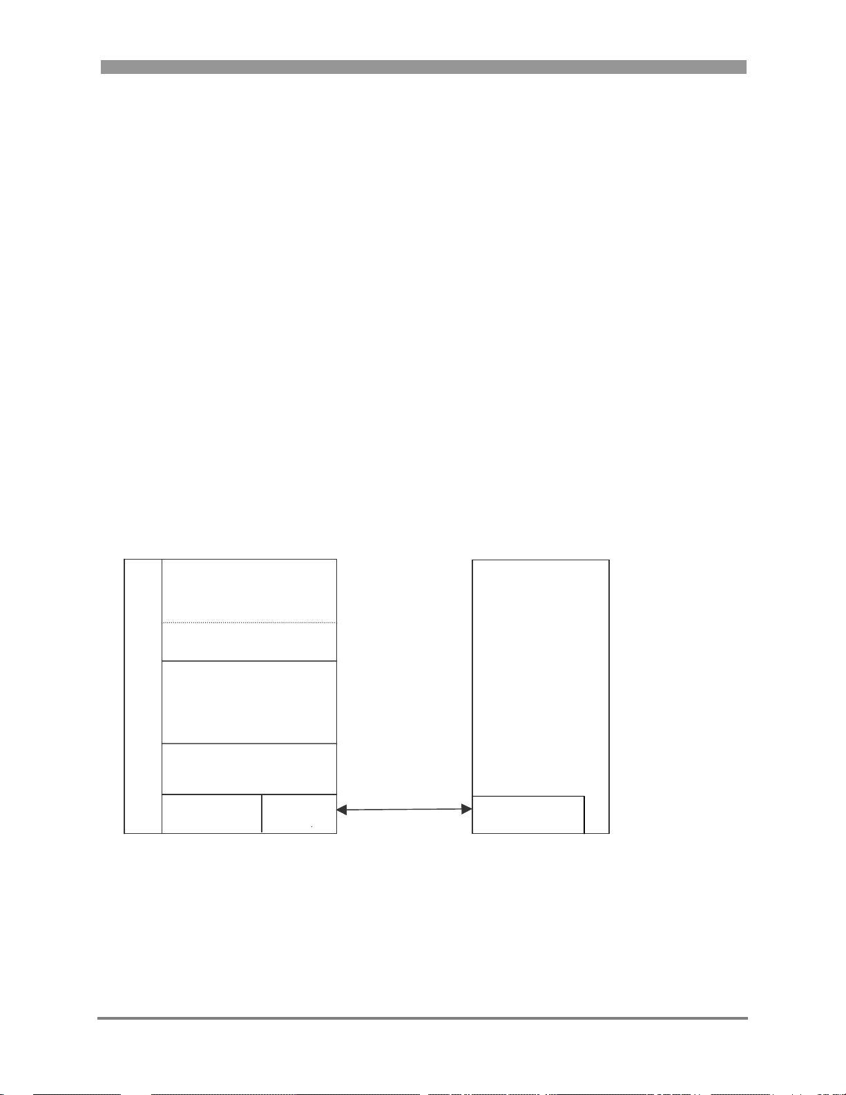
2.1.1 Use Case One
In this case, users send a specific command via the UART to enable firmware upload
(1)
MC908HCS08GB60
B Application Test Tool
o
o NVM
t
l 802.15.4 MAC
o
a
d 802.15.4 PHY
e RS232
r Device Driver UART
1)
Or MC908HCS08GT60
2)
Or USB
/MC13192 PC
(2)
UART or USB
Figure 1 Application Supporting RS232 UART or USB Inter face
Freescale Semiconductor Embedded Bootloader Reference Manual, Rev. 0.0 2-1
Page 14
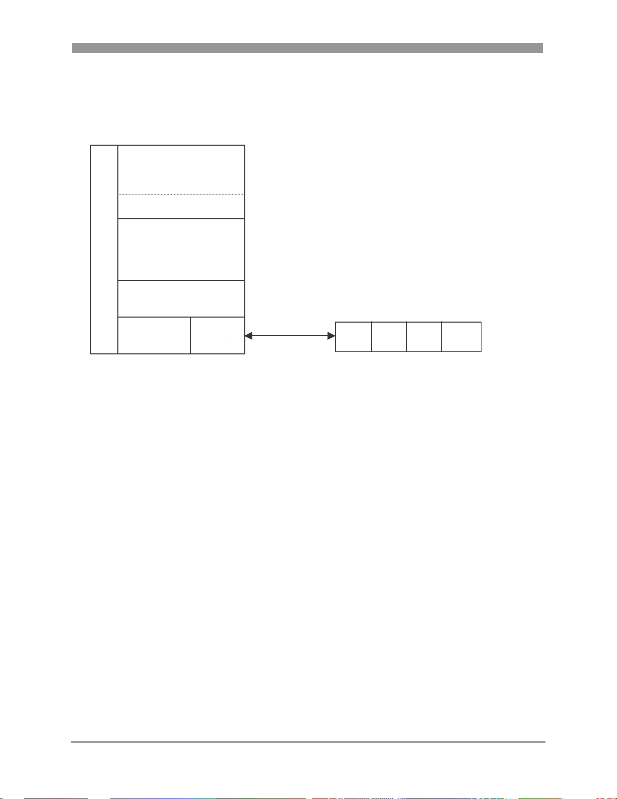
2.1.2 Use Case Two
In this use case, users push a button on the board to enable firmware upload.
MC908HCS08GB60
B Application
o
o NVM
t
l 802.15.4 MAC
o
a User Interface
d 802.15.4 PHY Push Buttons
e I/O
r Device Driver GPIO S101 S102 S103 S104
(1)
/MC13192
1)
Or MC908HCS08GT60
Figure 2 Application Supporting an I/O Interface
2.1.3 Safe Mode Boot
The Safe Mode Boot Mode is a special startup mode where the Embedded Bootloader boots using safe
system settings thereby resetting the system to a known (default) state.
The Safe Mode Boot can be used to disable the detection of an invalid/malfunctioning application due to
items such as code errors, corrupt NVM data, or internal flash programming errors among others. All the
NVM memory (except production data and MAC address) is completely erased.
The Safe Mode Boot can also be used to upload firmware without first calling the
Enable_Download_Firmware() function. This could be useful if the use cases (as shown in Section 2.1,
Upload Firmware) are not applicable.
Users must perform the following steps to conduct a Safe Mode Boot.
1. Power off the board
2. Disconnect RS232 UART cable (if the RS232 UART interface is used)
3. Short UART TX and RX (pin 2-3) (This works even though the 802.15.4/Zigbee application does not
use the UART interface.)
4. Power up again. All LEDs are off.
5. Wait until LED1 goes on (< 1 second)
6. Power off the board
2-2 Embedded Bootloader Reference Manual, Rev 0.0 Freescale Semiconductor
Page 15

7. Remove short from UART TX and RX and connect UART cable again (if the RS232 UART interface
is used)
8. Power up again
9. Embedded Bootloader is ready to receive new firmware (all LEDs on)
10. Start the PC-Tool. See Chapter 3, for more information.
NOTE
The Safe Mode Boot description is only valid for the Freescale ported
versions of the Embedded Bootloader. Refer to the 802.15.4 Embedded
Bootloader Reference Manual, 802154EBRM/D, for more details about a
specific port of the Embedded Bootloader.
2.2 Updating Non-volatile Memor y (NVM)
The following steps show how to update the NVM data from an application (code).
1. The Embedded Bootloader must be present on the board.
NOTE
All EVBs are shipped with the Embedded Bootloader pre-programmed
in flash. The Embedded Bootloader can only be erased/programmed with
a BDM debugger.
2. Call the Update_NV_RAM() function. This function can change any NVM data.
2.2.1 An Example of How to Change the MAC Address
The following code shows an example of how to change the MAC address.
Update_NV_RAM(&(NV_RAM_ptr->MAC_Address)[0], &pPacket[DATA_INDEX], 8);
NOTE
pPacket – contains the new MAC address.
Any NVM data can in code be read as a normal construct. For example,
use the NV_RAM_ptr to get access to individual data.
Freescale Semiconductor Embedded Bootloader Reference Manual, Rev. 0.0 2-3
Page 16

2.3 System Bus Frequency
The MC908HCS08GB60/GT60 starts in 4 MHz self clocked mode. The init code changes this to 8 MHz
after a few instructions from reset.
If NVM data is found, the system clock (MC908HCS08GB60/GT60 ICG module and MC13192 CLKO)
and other options are setup as specified by the uploaded application. See the Freescale 802.15.4
MAC/PHY Software Reference Manual, 802154MPSRM/D, for more details.
If no NVM data can be found, the following (safe mode boot) values are used:
• MC13192 CLKO = 62.5 KHz
• MC908HCS08GB60/GT60 bus clock = 16 MHz
2.4 UART Baud Rate
If NVM data is found, the UART baud rate is setup as specified by the uploaded application. Several
values can be used. See the MC908HCS08GB60/GT60 MCU Data Sheet, MC9S08GB60/D for more
information.
The baud rate depends on the NVM values specified by the application. See the Freescale 802.15.4
MAC/PHY Software Reference Manual, 802154MPSRM/D, for more details.
If no NVM data is found, the following (safe mode boot) values are used:
• UART baud rate 19200 kbps, 8 data, 1 start, 1 stop, none parity.
2-4 Embedded Bootloader Reference Manual, Rev 0.0 Freescale Semiconductor
Page 17

Chapter 3
Test Tool – Zigbee Flash Tool
The Zigbee flash tool is a part of the general Zigbee Test Tool. This chapter provides a brief description
of how to use the Zigbee Test Tool to upload new firmware. For more details about installation and other
features, see the documentation for the Zigbee Test Tool and the Zigbee.hlp file in Test Tool installation
directory .\help.
The flash programming part of the Test Tool can be used with two different user interfaces.
1. The GUI-version in ‘Test Tool.exe’
2. The command line version in ‘Bootloader.exe’ in the ‘S19’ folder.
This description covers Embedded Bootloader version 5.00 of the Zigbee Test Tool.
Uploadable applications in Motorola S19 file format must be copied to the
[installation directory]\Freescale\Test Tool\S19 directory in advance.
Copy any new applications in S19 format to this folder.
NOTE
The actual window layout may differ from the figures shown in this
document. Refer to the Freescale Zigbee/802.15.4 web page for new or
updated applications.
Freescale Semiconductor Embedded Bootloader Reference Manual, Rev. 0.0 3-1
Page 18
3.1 Graphical User Interface (GUI) Version
To use the GUI version of the Test Tool, execute the following file:
[installation directory]\Freescale\Test Tool\Test Tool.exe
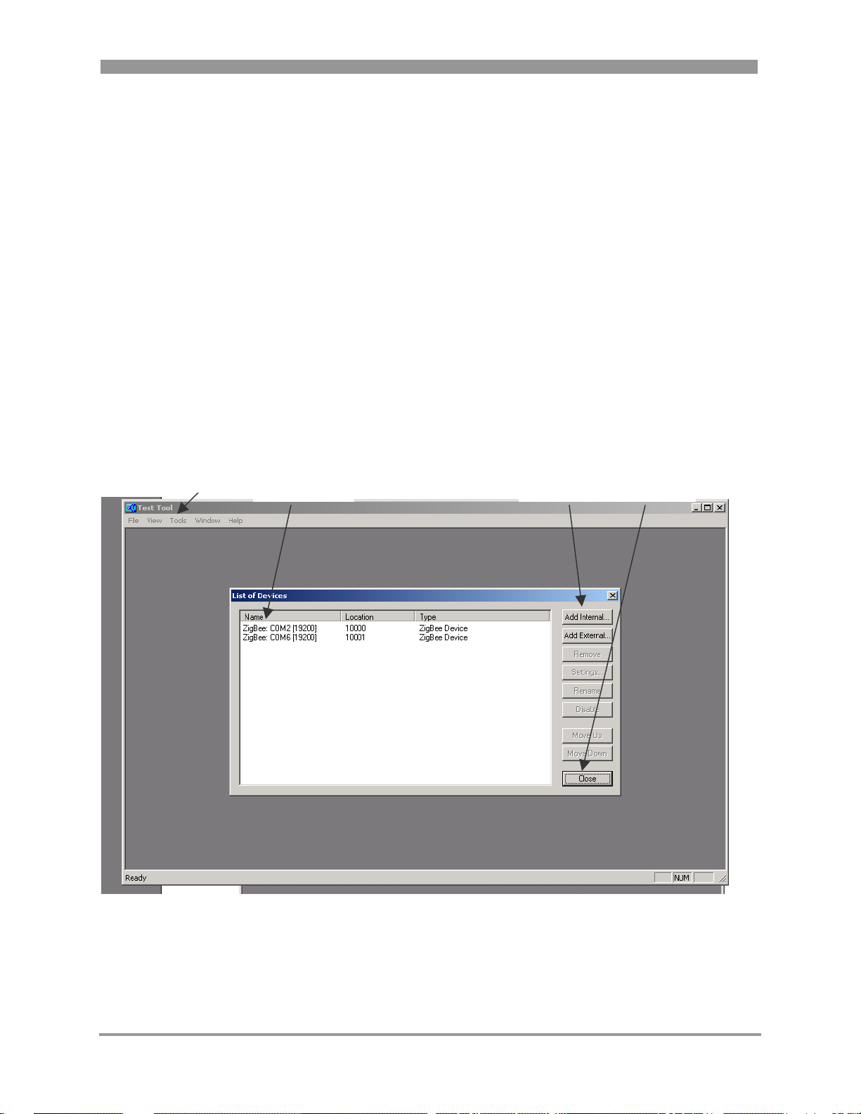
3.1.1 Using the Tools Menu Option
After clicking on the Tools menu option, click the Communication Settings option to choose the baud rate
specified for the current embedded application.
Notice that applications require that you push one or more buttons or some other functions to enable
upload of new firmware. See the Zigbee/802.15.4 Evaluation Kit Quick Start Guide, AN2772/D, for a
description of what to do for a specific application.
If no application is downloaded, use the default settings specified for the Embedded Bootloader. See
Chapter 2 for more information.
Use the Add… buttons. Click “Close”.
Tools Menu
Baud Selection
Buttons
Add Buttons Close Button
Figure 3 Tools Menu Selection
3-2 Embedded Bootloader Reference Manual, Rev 0.0 Freescale Semiconductor
Page 19
3.1.2 Using the View Menu Option
After clicking the View menu option, select port COMx and click “OK”. Choose the baud rate specified
for the current embedded application. See the Zigbee/802.15.4 Evaluation Kit Quick Start Guide,
AN2772/D, for a description of what to do for a specific application.
If no application is uploaded, you must use the default settings specified for the Embedded Bootloader.
See Chapter 2 for more information.
NOTE
If the USB interface is used, the USB option appears as a new COM port.
Figure 4 View Menu Option
Freescale Semiconductor Embedded Bootloader Reference Manual, Rev. 0.0 3-3
Page 20
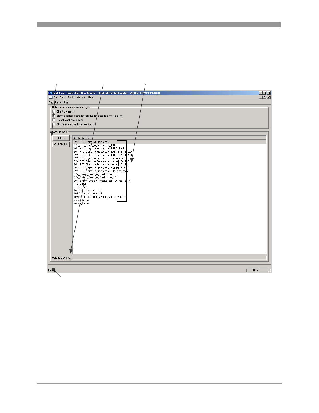
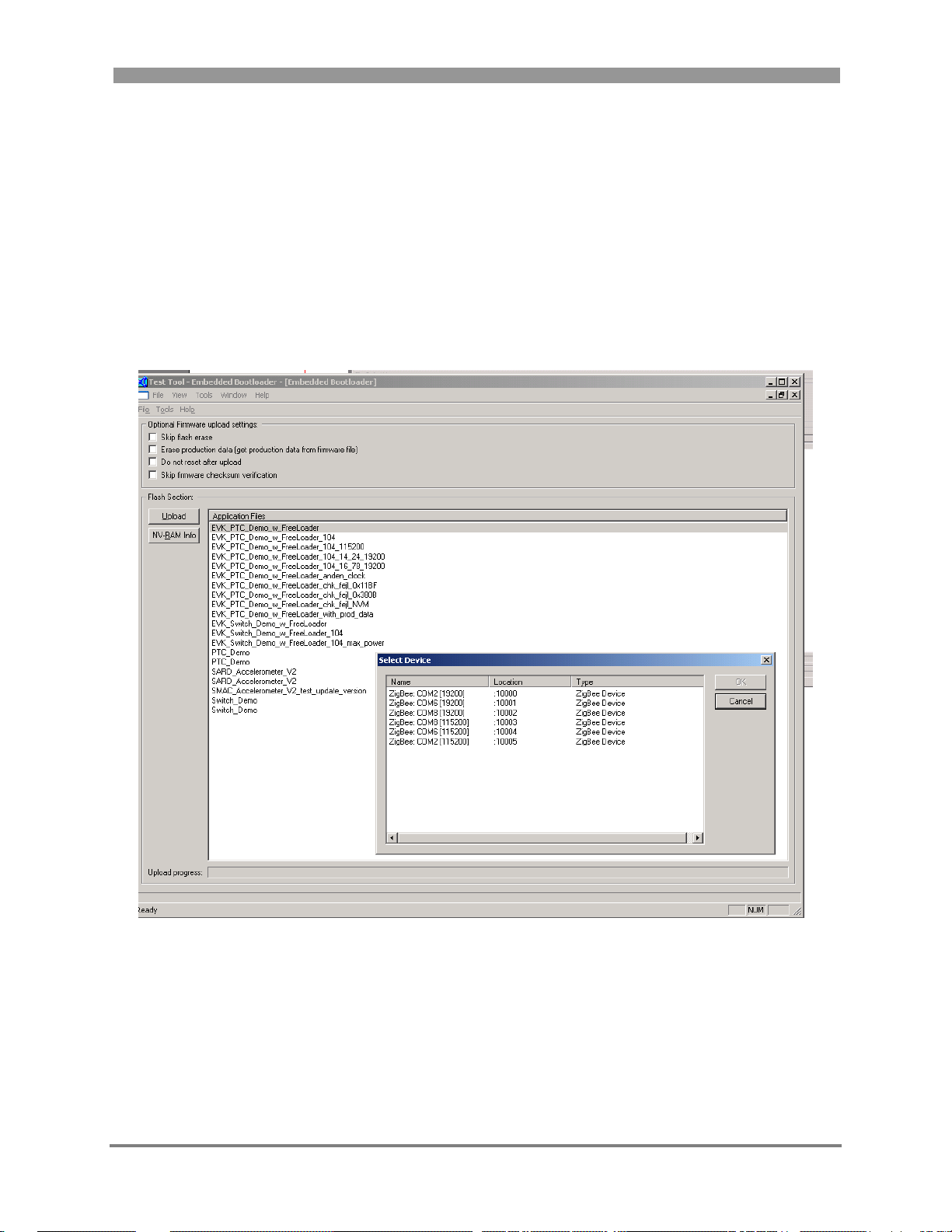
3.1.3 Selecting the Firmware File to Upload
In the ‘Flash Section’ window, click on the application file to upload and then click on the “Upload”
button. The upload progress bar begins to indicate upload progress.
Upload Button
Upload
Progress Field
Application
Files
Status/Error
Information Field
Figure 5 Firmware Upload
The Status/Error Information Field shows the Status/Error Information received from the Embedded
Bootloader.
3-4 Embedded Bootloader Reference Manual, Rev 0.0 Freescale Semiconductor
Page 21

After a successful upload of the firmware, the window appears as shown in Figure 6.
NOTE
A system reset is performed (default) after upload as shown in Figure 6.
Automatic Reset
Enabled
Figure 6 After a Successful Firmware Upload
NOTE
If the uploaded application uses another baud rate, it is required to
change baud rate values in order to be able to communicate with the
board.
Freescale Semiconductor Embedded Bootloader Reference Manual, Rev. 0.0 3-5
Page 22

3.1.4 Using the Help Menu
Click on the Embedded Bootloader About box to see the Embedded Bootloader sub version number.
Figure 7 Embedded Bootloader Tool Version
NOTE
The last line is reported from the Embedded Bootloader on the PCB.
This version number is only sent to the PC from power up (not on
reset).
3.1.5 Changing the NVM Data in Flash or File
If users click on an application in the list, it displays the NVM values in the selected application file. If
the uploaded application supports NVM dump, it is possible to read the NVM from the board.
The NVM data can be changed in two different ways:
1. If the uploaded application does not support NVM data editing it is possible to edit the NVM data
in the application file before it is uploaded to the board and save it back in the application file for
later upload.
2. If the uploaded application does support NVM data editing it is possible to edit the NVM data
after the board has been uploaded with the application. For example, the file contains default
values. The Freescale EVK PTC application supports this feature.
NOTE
No production specific information is available in this example window.
Use caution when editing the clock related configuration values. The
values must match each other. There is no sanity check on the user
entered values, though there is a check on length. See the
MC908HCS08GB60/GT60 MCU Data Sheet, MC9S08GB60/D about
how to specify valid register values for the HCS08.
3-6 Embedded Bootloader Reference Manual, Rev 0.0 Freescale Semiconductor
Page 23

Figure 8 System Configuration Window
Freescale Semiconductor Embedded Bootloader Reference Manual, Rev. 0.0 3-7
Page 24

3.2 Command Line Version (CMD)
The command line version of the Embedded Bootloader flash programming tool must be called with
parameters:
Execute ‘Bootloader.exe’ without parameters to show a parameter list:
Figure 9 Command Line Version (Parameter List)
3-8 Embedded Bootloader Reference Manual, Rev 0.0 Freescale Semiconductor
Page 25

3.2.1 Normal Use Example (Default)
Normal use example (default).
”Bootloader EVK_PTC_Demo.s19 /C:COM2 /B:19200 /-E /-A /-O /-S”
Figure 10 Command Line Version (Using Several Options)
NOTE
It is not possible to edit NVM data with the CMD version.
3.2.2 Flash Erase Disabled Example
Flash erase disabled example.
”Bootloader EVK_PTC_Demo.s19 /C:COM2 /B:19200 /E /-A /-O /-S ”
Figure 11 Command Line Version (Flash Erase Disable Option)
NOTE
The flash is not erased and a flash programming error is detected at
address 0xEFFE. This is the address of the Embedded Bootloader control
flags, which was not erased. The error message is expected.
Freescale Semiconductor Embedded Bootloader Reference Manual, Rev. 0.0 3-9
Page 26

3-10 Embedded Bootloader Reference Manual, Rev 0.0 Freescale Semiconductor
Page 27

Chapter 4
Embedded Bootloader Programming
This chapter describes how to program the Embedded Bootloader with a P&E Multilink for HCS08 BDM
debugger. The Embedded Bootloader is normally downloaded to the PCB where production data is also
written. Users must employ different procedures depending on what needs to be programmed. Users can
program the Embedded Bootloader to an empty (erased) PCB or they can upgrade to a newer version of
the Embedded Bootloader. Follow the procedures in Section 4.1, Programming To An Empty (Erased)
Board if the PCB is empty (erased).
Users must make a copy of the production data section in the NVM (see Section 5.3.5, NV_Data.c and
NV_Data.h) if they need to upgrade the Embedded Bootloader. This can be done either manually or
automatically by a custom made script with the command line version of the CPROG tool. The command
line version is not described further. Follow the procedures as shown in Section 4.2 on how to make a
copy of the production data.
4.1 Programming To An Empty (Erased) Board
This section describes how to program the Embedded Bootloader to an empty (erased) board.
1. Execute the HIWAVE.EXE file from your chosen installation directory. For example,
[installation directory]\Metrowerks\CodeWarrior_CW08_V3.0\Prog\
2. From the main window, setup the target by selecting the “Component” menu, then click on “Set
Target”. The “Set Target” window appears as shown in Figure 12.
Figure 12 Set Target Window
3. In the “Processor” drop down menu, select HCS08. From the “Target Interface” drop down menu,
select P&E Target Interface, the click on the “OK” button.
Freescale Semiconductor Embedded Bootloader Reference Manual, Rev. 0.0 4-1
Page 28

The “Connection Assistant” window appears where you can select the debugger interface connection.
As shown in Figure 13, a USB connection was chosen and the HCS08 was selected as the CPU type.
Click the “OK” button.
Figure 13 Connection Assistant Window
4-2 Embedded Bootloader Reference Manual, Rev 0.0 Freescale Semiconductor
Page 29

4. Click on “Load Application” under the “File” menu to open the “Load Executable File” window.
Specify application file to program in the “Load Executable File” window as shown in Figure 14.
Select “Motorola S-Record (*.s19)” using the “Files of type:” drop down menu. Navigate to the
folder where a copy of the Embedded Bootloader is located. Select the “Embedded Bootloader.s19”
file and click the “Open” button.
Figure 14 Load Executable Window
Freescale Semiconductor Embedded Bootloader Reference Manual, Rev. 0.0 4-3
Page 30

The Embedded Bootloader is now programmed to the PCB as shown in the Status Window in Figure 15.
Figure 15 Status Window
5. Remove power and disconnect the BDM cable from the PCB. Next, power up the PCB. The PCB is
now ready to upload an application. See Chapter 2 for details about how to upload an application.
4-4 Embedded Bootloader Reference Manual, Rev 0.0 Freescale Semiconductor
Page 31

4.2 Upgrading The Embedded Bootloader
This section describes how to upgrade the Embedded Bootloader to a newer version with the P&E
Multilink BDM debugger.
1. Execute the HIWAVE.EXE file from your chosen installation directory. For example,
[installation directory]\Metrowerks\CodeWarrior_CW08_V3.0\Prog\
2. From the main window, setup the target by selecting Setup Target, the select the “Component” menu,
and click on “Set Target”. The “Set Target” window appears as shown in Figure 16.
Figure 16 Set Target Window
3. From the “Processor” drop down menu, select HCS08. From the “Target Interface” drop down menu,
select P&E Target Interface, then click the “OK” button.
Freescale Semiconductor Embedded Bootloader Reference Manual, Rev. 0.0 4-5
Page 32

4. The “Connection Assistant” window appears where you can select the debugger interface connection.
As shown in Figure 17, a USB connection was chosen and the HCS08 was selected as the CPU type.
Click the “OK” button.
Figure 17 Connection Assistant Window
4-6 Embedded Bootloader Reference Manual, Rev 0.0 Freescale Semiconductor
Page 33

5. Make a copy of the NVM sector (both NVM0 and NVM1) with the production data.
Select the “PEDebug” menu, select “Programming Options”, and then choose “Start Expert Mode
Programmer”. The “Programmer Expert” window appears as shown in Figure 18.
Figure 18 Programmer Expert Window
6. In the “Programmer Expert” window, click on “UR Upload Range”. The “Start Address” window
appears as shown in Figure 19. Here you specify the start address for the NVM section. Click the
“OK” button. For NVM0 use 0x152F and for NVM1 use 0x172F.
Figure 19 Start Address Window
7. In the “End Address” window, which looks very similar to the “Start Address” window, specify the
end address for the NVM section and then click the “OK” button. For NVM0 use 0x155B and for
NVM1 use 0x175B.
Freescale Semiconductor Embedded Bootloader Reference Manual, Rev. 0.0 4-7
Page 34

8. As shown in Figure 20, use the S19 window to specify which S19 file to store active NVM data to
and then click the “OK” button. For NVM0 use ‘PD_NVM0.s19’ and for NVM1 use
‘PD_NVM1.s19’.
Figure 20 S19 File Window
9. Close “Programmer Expert” window.
10. Use the PC tool “Production_Data_Converter.exe” to convert the production data in NVM to default
NVM sector NVM0. Copy the “Production_Data_Converter.exe” tool to the folder that contains the
PD_NVM0.s19 and PD_NVM1.s19 files. Execute the ‘Production_Data_Converter.exe’. The output
is an PD_NVM.s19 file containing the production data from the active NVM sector.
NOTE
The “Production_Data_Converter.exe” tool can be found in the EVK release
“EVK_3_0B” in folder .\source\Zigbee_EVK\EVK_Common\CPROG_Tool\Scripts\
11. Click on “Load Application” under the “File” menu to open the “Load Executable File” window.
Specify the application file to program using the “Load Executable” window as shown in Figure 21.
Select the “Motorola S-Record (*.s19)” under “Files of type:”, then navigate to the folder where a
copy of the Embedded Bootloader is located. Select the “Embedded Bootloader.s19” file and click the
“Open” button.
Figure 21 Load Executable File Window
4-8 Embedded Bootloader Reference Manual, Rev 0.0 Freescale Semiconductor
Page 35

The Embedded Bootloader is now programmed to the PCB as shown in Figure 22.
Figure 22 Status Window
12. Write NVM production data back by selecting the “PEDebug” menu. Then select “Programming
Options” and “Start Expert Mode Programmer”. Select “SS Specify S-record” and locate the
PD_NVM.s19 file built in Step 10. Select the “PM Program Module” option and production data is
written to flash.
13. Remove power and disconnect the BDM cable from PCB. Next, power up the PCB.
The PCB is now ready to upload an application. See Chapter 2 for more information about how to
upload an application.
NOTE
The applications must have the production section in the NVM cleared.
That is, the application image must contain 0xFF's in the production data
section of the NVM.
Freescale Semiconductor Embedded Bootloader Reference Manual, Rev. 0.0 4-9
Page 36

4-10 Embedded Bootloader Reference Manual, Rev 0.0 Freescale Semiconductor
Page 37

Chapter 5
Application Integration Reference Guide
This chapter describes the deliverables required to build an 802.15.4/Zigbee Application with the
Embedded Bootloader.
NOTE
The Freescale Switch Demonstration application is available with
complete source code. The Switch Demonsration shows how to make an
802.15.4 application with the Embedded Bootloader. Refer to the Switch
Demonstration Application Note, AN2773, for more details.
5.1 Product Deliverables
To be able to make an application with the Freescale Embedded Bootloader, you need three major
components.
• Embedded Bootloader Image
• Application Support Files
• Application Linker File
5.1.1 Embedded Bootloader Image
The Embedded Booloader executable image for a specific PCB must exist on the PCB in advance. If not,
it must be downloaded to the PCB with a BDM debugger like the P&E Multilink BDM debugger for
HCS08. See Section 1.1.1 Ported Targets for more details.
NOTE
Use caution when making an 802.15.4/Zigbee Application with the
Embedded Bootloader. Several versions (different version numbers) exist
with different supported features. Ensure that you do not use a feature
that is not supported by the Embedded Bootloader version on the PCB
and that a version of the Embedded Bootloader is preloaded on the PCB.
5.1.2 Application Suppor t Files
A few application source files must be included in the 802.15.4/Zigbee application for proper interface to
the Embedded Bootloader. See Section 5.3, Application Support Files for more details.
Freescale Semiconductor Embedded Bootloader Reference Manual, Rev. 0.0 5-1
Page 38

5.1.3 Application Linker File
The 802.15.4/Zigbee application code must be linked with the following linker file in order to work with
the Embedded Bootloader interface. The linker file specifies fixed data and code segments. See linker file
for more details. Make sure to use the linker file matching the Embedded Bootloader on the PCB:
Ptc_w_Embedded_Bootloader.ach
NOTE
This file can be used with the MC908HCS08GB60/GT60 MCU.
5.2 Application
This section describes build environment topics and source files necessary to build a working
802.15.4/Zigbee application with the Embedded Bootloader.
5.2.1 Compiler Defines
The following compiler #define must be specified to enable Embedded Bootloader functionality in an
802.15.4/Zigbee application:
#define BOOTLOADER_ENABLED
5.2.2 Unreferenced Symbols
The Embedded Bootloader interface variables, NVM, and strings with version numbers, are not
referenced directly from the 802.15.4/Zigbee application code. Because of this, it is required to add
dummy references to these (and other) unreferenced symbols to prevent the linker file from removing the
symbols during optimization. The dummy references can be placed in any reference function, but
Freescale recommends adding them to the main() function.
The following code is an example from a SMAC application main() function:
#ifdef BOOTLOADER_ENABLED
if( (Freescale_Copyright[0] == 0x00) ||
(Firmware_Database_Label[0] == 0x00) ||
(SMAC_Version[0] == 0x00) ||
(SPHY_Version[0] == 0x00) ||
(NV_RAM_ptr->Freescale_Copyright[0] == 0x00) ||
(NV_RAM0.MAC_Address[0] == 0x00) ||
(NV_RAM1.MAC_Address[0] == 0x00) ||
(boot_loader_control == ((uint8_t)0x00)) ||
(boot_loader_flag == ((uint8_t)0x00))
)
5-2 Embedded Bootloader Reference Manual, Rev 0.0 Freescale Semiconductor
Page 39

{
// Do something to aviod that code is removed by linker
}
5.2.3 System Clock Setup
The Embedded Bootloader contains the ICG_Setup() function which is called if the Embedded
Bootloader must start. The Embedded Bootloader sets up the system clock as specified in the NVM
section (ICG) if available. If not a default value is used.
The 802.15.4/Zigbee application must include a system clock setup function. The 802.15.4/Zigbee
application can access the clock setup FL_ICG_Setup() function in the Embedded Bootloader. This
allows the application to save code space for implementing a system clock setup function. Any clock
setting can be setup by specifying the proper ICG register values in the NVM data section.
The 802.15.4/Zigbee application should also have a “lost clock lock” ISR function which calls the
FL_ICG_Setup() function. This function must be added to the ISR vector table.
The following is an example of an ISR function to handle lost lock of clock (CLKO).
__interrupt void FLL_Lost_Lock_ISR(void)
{
// Setup ICG module again to prevent that system hangs forever.
ICGS1 |= 0x01; // Clear FLL lost lock interrupt
#if defined BOOTLOADER_ENABLED
FL_ICG_Setup(); // Call ICG_Setup()in Embedded Bootloader
#endif defined BOOTLOADER_ENABLED
}
5.3 Application Support Files
The 802.15.4/Zigbee application must include some support source code to make an interface to the
Embedded Bootloader application. The needed files are delivered to users who want to use the Embedded
Bootloader in their system.
NOTE
Some of the files are global header files from the 802.15.4 MAC/PHY release.
Look for new or updated application support files at the Freescale
Zigbee/802.15.4 web page.
5.3.1 DigiType.h
This file contains some C-language type definitions used in the source files.
5.3.2 Gb60_io.h
This is an MC908HCS08GB60 MCU interface file. All peripherals embedded in the MCU are listed with
their absolute addresses.
Freescale Semiconductor Embedded Bootloader Reference Manual, Rev. 0.0 5-3
Page 40

NOTE
This file can also be used with the MC908HCS08GT60 MCU.
5.3.3 Crt0.c and Crt.h
These files contain the basic initialization code (basic system clock, memory and stack setup). The normal
basic init file(s) (like the start08.c from Metrowerks) is not needed when the Embedded Bootloader is
embedded.
In an 802.15.4/Zigbee application with Embedded Bootloader, these files only contain the _startupdata
structure. The Embedded Bootloader handles all the basic initialization (memory and stack setup) of the
application. That is, the application’s main() function will be the first item called (entry point).
NOTE
Do not include basic initialization (memory and stack setup) when
building an application with the Embedded Bootloader. Place any
necessary initialization function calls in the main() function. Whatever,
the initialization function or only the _startupdata structure is included is
controlled by compiler #defines. See Section 5.2.1, Compiler Defines
Application for more information.
5-4 Embedded Bootloader Reference Manual, Rev 0.0 Freescale Semiconductor
Page 41

5.3.4 Embedded_Bootloader.h and Embedded_Bootloader .c
These are the interface files for the 802.14.4/Zigbee application. They contain function pointers to
functions accessible in the Embedded Bootloader. These files also contain absolute addresses, which
should not be changed.
Ensure that the two Embedded Bootloader control flags, which control whether the 802.15.4/Zigbee
application starts or not, are included in the 802.15.4/Zigbee application build. See Section 5.2.2 for more
details.
#pragma CONST_SEG APP_BOOTLOADER_FLAGS
// Default setting for how BootLoader downloads firmware
const uint8_t boot_loader_control = ALL_BIT_ENABLED;
const uint8_t boot_loader_flag = EXECUTE_APPLICATION;
#pragma CONST_SEG DEFAULT
The 802.15.4/Zigbee application must also call the “void BootLoader_Interface_Init(void)” function to
set up pointers to the Embedded Bootloader accessible function. The function must be called once during
system initialization.
NOTE
In earlier versions, these files were titled “FreeLoader_inf.c” and
“FreeLoader_inf.h”. Do not user the “FreeLoader_inf.c” and
“FreeLoader_inf.h” files with the Embedded Bootloader.
5.3.5 NV_Data.c and NV_Data.h
The NVM is not a part of the Embedded Bootloader. However, it is advised to make the NVM a part of
the 802.15.4/Zigbee application.
The Embedded Bootloader can use the information in NV memory, but it has default values (safe mode
boot) to cover scenarios where no NV memory is available, that is, the Embedded Bootloader would be
locked to use the default values.
5.3.6 ISR_Vectors.c
The Embedded Bootloader redirects the ISR vector table to 0x0EFC0, i.e. the 802.15.4/Zigbee application
ISR vector table must be locate at 0x0EFC0 to 0xEFFD (see linker file).
The file also contains a reset vector. The reset vector is not used (defined out) when using the Embedded
Bootloader. The system reset vector is in the Embedded Bootloader address space (0xFFFE). The
Embedded Bootloader has two system variables located where the redirected “reset vector” is locate at
0xEFFE to 0xEFFF. The variables control the startup of the Embedded Bootloader.
Freescale Semiconductor Embedded Bootloader Reference Manual, Rev. 0.0 5-5
Page 42

5.3.7 DummyIsr.c
This file contains a dummy ISR function which makes a break if a BDM debugger is attached to the
BDM connector. An illegal instruction reset occurs if no BDM debugger is attached. The function is
added to all unused ISR vectors in the ISR_Vector.c file.
NOTE
Users can change this function to any desired functionality.
5-6 Embedded Bootloader Reference Manual, Rev 0.0 Freescale Semiconductor
Page 43

Chapter 6
Port Integration Reference Guide
This chapter describes the Embedded Bootloader source code release deliverables and how to integrate
them to make an executable Embedded Bootloader for a specific PCB.
NOTE
For user convenience, several readme.txt files containing more
information are located in various subfolders.
6.1 Embedded Bootloader Build Environment
This chapter describes the Embedded Bootloader build environment. The Embedded Bootloader
application is built under the Metrowerks IDE CodeWarrior Development Studio for Freescale HC08 3.0,
build 030506.
6.1.1 HCS08 Compiler
All Embedded Bootloader source files are compiled with the following compiler and with the ‘Generate
Code for HCS08’ Code Generation option enabled.
Source file: hw_hc08_compiler.dll, version 5.0.8.0
Setting: -Cs08 -CswMaxLF0 -CswMinLF0 -CswMinSLB9999 -Lasm=%n.lst -Lasmc=h -
Ot -Ou -Onf -OnB=alr -OnCstVar -OnPMNC -Or -TE1uE -WmsgNu=acdet
6.1.2 HCS08 Linker
All Embedded Bootloader object files are linked with the following linker to build an executable file.
Source file: hw_hc08_linker.dll, version 5.0.8.0
Setting: -B -EnvSRECORD=s19 -EnvTEXTPATH=Zigbee_Data\Zigbee_Debug\ -
The Embedded Bootlaoder MUST be linked with the following linker file.
.\Embedded_Bootloader\prm\Embedded_Bootloader_HCS08.ach
Specific allocated code and variables must not be reallocated, but users can add new code and data
segments.
The 802.15.4 and Zigbee applications that interface to the Embedded
Bootloader must be linked with the "Ptc_w_Embedded_Bootloader.ach"
file for proper functionality.
WStdoutOn
NOTE
6.1.3 HCS08 LibMaker
The delivered libraries were made with the following libmaker.
Freescale Semiconductor Embedded Bootloader Reference Manual, Rev. 0.0 6-1
Page 44

Source file: hw_hc08_libmaker.dll, version 5.0.8.0
Setting: None
6.2 Product Deliverables
The Freescale Embedded Bootloaader consists of four major components. Refer to Appendix A for a
complete list of released files.
6.2.1 Embedded_Bootloader.mcp
This is the Metrowerks Codewarrior mcp project file. This file is used to build the release of the
Embedded Bootloader.
NOTE
It is required that you have Metrowerks Codewarrior installed on your PC to build the
Embedded Bootloader.
6.2.2 HCS08_Flash_Lib.Lib
The library contains functions to write to the internal flash of the HCS08 MCU. The library also contains
functions to handle NVM run-time updates.
The flash library version number is found by searching for the ASCII text string “HCS08 Flash Lib” in
the ‘HCS08_Flash_Lib.Lib’. The version number is only available from flash library version 5.00.
NOTE
The HCS0_Flash_Lib.Lib can also be included directly in an application
for run-time update of NVM. Refer to the HCSO8 Flash Application
Note, AN2770/D for more information.
6.2.3 Embedded_Bootloader_Functionality_Lib. Lib
The library contains the internal functionality of the Embedded Bootloader. For example, the state
machine which handles the firmware download, the UART drivers, checksum verification functions and
others.
The Embedded Bootloader functionality library version number is found by searching for the ASCII text
string “EB Func Lib” in the ‘Embedded_Bootloader_Functionality_Lib.Lib’ file.
6.2.4 Source Files
This section provides a brief description of the source files. Refer to Appendix A for more details. The
source files described are those which define the PCB interface. For example, the I/O mapping that
connects the MCU and RF chip.
Embedded_Bootloader_Target.h Specific Embedded Bootloader defines
For example, the Embedded Bootloader version number.
6-2 Embedded Bootloader Reference Manual, Rev 0.0 Freescale Semiconductor
Page 45

HW_Init.c Hardware init functions
HW_Init.h Init function prototypes and defines.
Reset_Vector.c System reset vector.
main.c Embedded Bootloader main function.
6.3 Porting to a Specific Target
This section provides guidelines on how to port the Embedded Bootloader to a specific PCB/target.
6.3.1 Code and Data Segments
The Embedded Bootloader must be linked with the linker file as specified in Section 6.1.2. Several code
and data segments are listed and must not be changed. Refer to the map file as described in Chapter 8 for
more details.
6.3.2 Standard Libraries
The Embedded Bootloader must include the ansiis.lib from Metrowerks for a successful build. The
library is part of the Metrowerks CodeWarrior installation and is located in the following path:
[Install Folder]\Metrowerks\CodeWarrior CW08_V3.0\lib\HC08c\*.*
6.3.3 Compiler #defines
No compiler #defines are necessary.
Freescale Semiconductor Embedded Bootloader Reference Manual, Rev. 0.0 6-3
Page 46

6.4 Source Files
This section describes the source files.
6.4.1 Target.h
The user must define the PCB target specific #defines in the Target.h in the
.\802.15.4_Headers\Ghdr. file for a successful port.
NOTE
Several other #defines are made in the target description in target.h. The
#defines are used by the 802.15.4 MAC/PHY build. The listed #defines
are the ones which must (also) be defined for the Embedded Bootloader:
Example for the Freescale TARGET_DIG528_2 and TARGET_DIG536_2:
MC13192 reset pin connection:
#define HWAssertAbelReset PTCD &= ~0x10; // Reset = 0;
#define HWDeAssertAbelReset PTCD |= 0x10; // Reset = 1;
Optional for Safe Mode Boot indicator function (LED pin connections):
#define LED1ON PTDD &= 0xFE;
#define LED1OFF PTDD |= 0x01;
#define LED1TOGGLE PTDD ^= 0x01;
#define LED2ON PTDD & = 0xFD;
#define LED2OFF PTDD | = 0x02;
#define LED2TOGGLE PTDD ^ = 0x02;
#define LED3ON PTDD & = 0xF7;
#define LED3OFF PTDD | = 0x08;
#define LED3TOGGLE PTDD ^ = 0x08;
#define LED4ON PTDD & = 0xEF;
#define LED4OFF PTDD | = 0x10;
#define LED4TOGGLE PTDD ^ = 0x10;
The MC13192 attention and reset pin (bit) positions:
#define ABEL_ATT_PIN (1<<2)
#define ABEL_RESET_PIN (1<<4)
HCS08 port setup macros:
#define mSETUP_PORT_A //PTAPE = 0x3C;\
6-4 Embedded Bootloader Reference Manual, Rev 0.0 Freescale Semiconductor
Page 47

//PTADD = 0x00; //All Port A input
#define mSETUP_PORT_B //PTBD = 0x00;\
//PTBPE = 0x00;\
//PTBDD = 0x00;
#define mSETUP_PORT_C PTCDD = (ABEL_RESET_PIN | ABEL_ATT_PIN );
Optional for Safe Mode Boot indicator function (LEDs as output):
#define mSETUP_PORT_D PTDPE = 0x00;\
PTDDD = (0x01 | 0x02| 0x08 | 0x10);
6.4.2 Reset_Vector.c
The system reset vector.
NOTE
The application does not have a reset vector. If a reset occurs in an
application, the Embedded Bootloader’s reset vector is called.
6.4.3 Embedded_Bootloader_Target.h
Users must define the following #defines in the Embedded_Bootloader_Target.h to achieve a successful port.
Version number of the build:
// Version number update:
// - Big change (interface/main code structure/new feature) Y.xx, increment
Y
// - Smaller change (function code structure/bug fix) x.Yx, increment Y
// - Small change (bug fix) x.xY, increment Y
#define EMBEDDED_BOOTLOADER_VERSION "5.01" // Number used with all PCB/Targets
NOTE
Use caution if the version number is changed. You should only change
the PCB board number (
to indicate a special PCB version.
Example for the TARGET_DIG528_2 and TARGET_DIG536_2:
#if defined TARGET_DIG528_2 || defined TARGET_DIG536_2
// PCB board number for release
#define EMBEDDED_BOOTLOADER_TARGET "528&536"
// Setup port as output where "signal" must be set/cleared to indicate
safe mode boot
#define SAFE_MODE_PORT_SETUP PTDDD |= 0x01; // Port D bit 0
#define EMBEDDED_BOOTLOADER_TARGET)
Freescale Semiconductor Embedded Bootloader Reference Manual, Rev. 0.0 6-5
Page 48

#define SET_OUTPUT LED1ON // Defined in Target.h
#endif defined TARGET_DIG528_2 || defined TARGET_DIG536_2
6.4.4 HW_Init.h
This file contains prototypes of all the init functions and defines.
6.4.5 HW_Init.c
This file contains some hardware init functions which depend on the PCB layout.
void HWResetAbel(void) Reset of MC13192 RF chip (do not change)
void Safe_Boot_Mode_Indicator(void) Users can change this function so it matches the
functions available for a particular PCB. The
function can also be left empty. Default is a GPIO
pin set low to light an LED.
void HW_Init() The init main function.
NOTE
User can add more functions if required for a particular PCB.
Do not change the calling sequence.
6.4.6 main.c
This file contains the Embedded Bootloader main function and the Embedded version number.
void main(void) It calls the hardware init function and then the
Embedded Bootloader state machine. The state
machine never returns.
NOTE
Dummy references are made to the version number strings for the
Embedded_Bootloader_Functionality_Lib and HCS08_Flash_Lib to
place the numbers in the executable image. If the version numbers are
not required, they can be removed by removing the reference to the
version number which frees up more code memory for user code.
6-6 Embedded Bootloader Reference Manual, Rev 0.0 Freescale Semiconductor
Page 49

Chapter 7
Embedded Bootloader Public Function Description
This section describes the public functions which the 802.15.4/Zigbee application can call in the
Embedded Bootloader.
7.1 802.15.4/Zigbee Application Accessible Functions
The following functions, located in the Embedded Bootloader, are made accessible for 802.15.4/Zigbee
applications. For example, an 802.15.4/Zigbee application is not required to have programming routines
to store NVM data in flash. A function pointer, for each function of the below listed functions, is defined
in Embedded Bootloader.c:
Enable_Download_Firmware()
Hard_Reset()
NV_Flash_Setup()
Update_NV_RAM()
FL_ICG_Setup()
UART_Port_Select();
The Embedded_Bootloader.h file contains function pointer prototypes and must be included in source
files calling these functions. The function pointers are setup to point to functions with the same name in
the Embedded Bootloader.
extern Enable_Download_Firmware_ptr_t Enable_Download_Firmware;
extern Hard_Reset_ptr_t Hard_Reset;
extern NV_Flash_Setup_ptr_t NV_Flash_Setup;
extern Update_NV_RAM_ptr_t Update_NV_RAM;
extern ICG_Setup_ptr_t FL_ICG_Setup;
extern UART_Port_Select_ptr_t UART_Port_Select;
7.1.1 Enable_Download_Firmware
Prototype:
bool_t Enable_Download_Firmware
(
uint8_t interface_state,
uint8_t firmware_state
)
Description:
The application must call this function to make the system ready for a new firmware download. The
application must provide a way for the user to interact with the system to call this function.
Freescale Semiconductor Embedded Bootloader Reference Manual, Rev. 0.0 7-1
Page 50

NOTE
All bits are enabled by default. Bits can only be disabled (erased in flash)
– never enabled. The bits are enabled again by the new firmware.
Input:
interface_state - The user selectable options. The below values should be
OR’ed together:
Embedded Bootloader control flags:
#define NO_BIT_ENABLED ((uint8_t)0x00)
// Option: “Skip flash erase”
#define ERASE_FLASH ((uint8_t)0x01)
// Option: “Do not reset after upload”
#define BOOT_AFTER_DOWNLOAD ((uint8_t)0x02)
// Option: “Erase production data”
#define KEEP_NV_RAM ((uint8_t)0x04)
// Option: “Skip firmware checksum verification”
#define PERFORM_FLASH_VERIFICATION ((uint8_t)0x08)
NOTE
The Embedded Bootloader control flags correspond to the “optional
firmware upload settings” which can be disabled/enabled in the Zigbee
Flash Tool. See Section 1.4.1, Embedded Bootloader Description for
details.
The value is inverted. To enable the bit mask option, the setting must be
set to 0. To disable the bit mask option, the setting must be set to 1.
Use firmware_state – control if Embedded Bootloader or the application must be started.
To enable download, the setting must be = DO_UPDATE_FIRMWARE.
Embedded Bootloader boot flag:
#define EXECUTE_APPLICATION ((uint8_t)0x55)
#define DO_UPDATE_FIRMWARE ((uint8_t)0x00)
#define FLASH_EMPTY ((uint8_t)0xFF)
Output:
True - Ready for reset.
False - Something went wrong in changing the state.
7-2 Embedded Bootloader Reference Manual, Rev 0.0 Freescale Semiconductor
Page 51

7.1.2 Hard_Reset
Prototype:
void Hard_Reset(void)
Description:
The application can call this function to make a system reset. The reset is done by executing an illegal
instruction.
Input:
None
Output:
None
7.1.3 Update_NV_RAM
Prototype:
bool_t Update_NV_RAM
(
NV_RAM_Struct_t const *NV_RAM_Distination_ptr,
uint8_t *Source_ptr,
uint16_t Source_Length
)
Description:
The application can call this function to update any NVM parameter with new values specified in the
input parameters. There is no validation of input parameters.
NOTE
NVM can in code be read as a normal construct.
Input:
NV_RAM_Distination_ptr A pointer to current NV RAM data (ex. The MAC address), which must be changed.
Source_ptr A pointer to new NVM data, which must be stored.
Source_Length The length (number of bytes) of the new NVM data to store.
Output:
True – NVM data stored.
False - Something went wrong (should never happen).
Freescale Semiconductor Embedded Bootloader Reference Manual, Rev. 0.0 7-3
Page 52

7.1.4 NV_Flash_Setup
Prototype:
void NV_Flash_Setup(void)
Description:
This function should never be called under normal conditions. However, it should be called if any of the
other Embedded Bootloader functions malfunctions. The function sets up the flash functions (again), i.e.
copies the flash routines to RAM for execution and initialize the HCS08 flash module.
Input:
None
Output
None
7.1.5 FL_ICG_Setup
Prototype:
void FL_ICG_Setup(void)
Description:
This function can be called by the application. The function could be automatically called if the external
system clock is unstable/removed (from ISR function) and on power down/up (doze). This requires that
the FL_ICG_Setup is called from an ISR function.
NOTE
Application programmers can make their own system clock setup
function or call this function and just modify the ICG and MC13192
register values in the NVM section.
Input:
None
Output
None
7-4 Embedded Bootloader Reference Manual, Rev 0.0 Freescale Semiconductor
Page 53

7.1.6 UART_Port_Select
Prototype:
void FL_ICG_Setup
(
uint8_t data_reg_address,
uint8_t status_reg_address
)
Description:
This function can be called when the application has detected the active communication interface if used
by the application. The communication interface can be any of the two SCI-ports (SCI1 or SCI2). When
called with the proper parameters the Embedded Bootloader knows the active communication interface.
Input:
data_reg_address the address of the active SCI port data register (SCI1 = 0x1F or SCI2 = 0x27 )
status_reg_address the address of the active SCI port status 1 register (SCI1 = 0x1C or SCI2 = 0x24)
Output
None
Freescale Semiconductor Embedded Bootloader Reference Manual, Rev. 0.0 7-5
Page 54

7-6 Embedded Bootloader Reference Manual, Rev 0.0 Freescale Semiconductor
Page 55

Chapter 8
Embedded Bootloader Memory Map
Table 1. Zigbee (MC9S08GB60/GT60) 802.15.4 Embedded Bootloader Memory Map
512 Bytes in a physical flash sector
Sector
Number
NM 0 7F 128 Direct Port Registers Direct Port Registers
NM 80 FE 127 Direct Addressing RAM
NM FF FF 1 Direct Addressing
NM 100 1FF 256 RAM Embedded Bootloader stack
NM 200 F5F 3424 RAM
NM F60 F6F 16 RAM Unint RAM for init structure
NM F70 F71 2 RAM NV_RAM_ptr
NM F72 F7F 14 RAM Flash routines data
Address
in hex
start
Address
in hex
end
(sector
erase
address)
Size in
bytes
General HCS08 Map
and Usage
"Fast memory"
RAM "Fast memory"
Embedded Bootloader Map
Direct Addressing RAM "Fast
memory"
Sleep variable:
gSeqPowerSaveMode
NM F80 FBC 61 RAM Flash routines critical code
NM FBD 106F 179 RAM
NM 1070 1077 8 RAM Static variables
NM 1078 107F 8 RAM Static no init variables
8 1080 109E 31 FLASH (section 1)
8 109F 11FF 353 FLASH (section 1)
9 1200 13FF 512 FLASH (section 1)
10 1400 15FF 512 FLASH (section 1) 802.15.4/App. NV RAM block
0 (share)
11 1600 17FF 512 FLASH (section 1) 802.15.4/App. NV RAM block
Freescale Semiconductor Embedded Bootloader Reference Manual, Rev. 0.0 8-1
Page 56

1 (share)
12 1800 182B 44 High Page Registers
(COP, Flash etc.)
12 182C 19FF 468 FLASH (section 2)
13 1A00 1BFF 512 FLASH (section 2)
14 1C00 1DFF 512 FLASH (section 2)
15 1E00 1FFF 512 FLASH (section 2)
16 2000 21FF 512 FLASH (section 2)
17 2200 23FF 512 FLASH (section 2)
18 2400 25FF 512 FLASH (section 2)
19 2600 27FF 512 FLASH (section 2)
20 2800 29FF 512 FLASH (section 2)
21 2A00 2BFF 512 FLASH (section 2)
22 2C00 2DFF 512 FLASH (section 2)
High Page Registers (COP,
Flash etc.)
23 2E00 2FFF 512 FLASH (section 2)
24 3000 31FF 512 FLASH (section 2)
25 3200 33FF 512 FLASH (section 2)
26 3400 35FF 512 FLASH (section 2)
27 3600 37FF 512 FLASH (section 2)
28 3800 39FF 512 FLASH (section 2)
29 3A00 3BFF 512 FLASH (section 2)
30 3C00 3DFF 512 FLASH (section 2)
31 3E00 3FFF 512 FLASH (section 2)
32 4000 41FF 512 FLASH (section 2)
33 4200 43FF 512 FLASH (section 2)
34 4400 45FF 512 FLASH (section 2)
35 4600 47FF 512 FLASH (section 2)
36 4800 49FF 512 FLASH (section 2)
8-2 Embedded Bootloader Reference Manual, Rev. 0.0 Freescale Semiconductor
Page 57

37 4A00 4BFF 512 FLASH (section 2)
38 4C00 4DFF 512 FLASH (section 2)
39 4E00 4FFF 512 FLASH (section 2)
40 5000 51FF 512 FLASH (section 2)
41 5200 53FF 512 FLASH (section 2)
42 5400 55FF 512 FLASH (section 2)
43 5600 57FF 512 FLASH (section 2)
44 5800 59FF 512 FLASH (section 2)
45 5A00 5BFF 512 FLASH (section 2)
46 5C00 5DFF 512 FLASH (section 2)
47 5E00 5FFF 512 FLASH (section 2)
48 6000 61FF 512 FLASH (section 2)
49 6200 63FF 512 FLASH (section 2)
50 6400 65FF 512 FLASH (section 2)
51 6600 67FF 512 FLASH (section 2)
52 6800 69FF 512 FLASH (section 2)
53 6A00 6BFF 512 FLASH (section 2)
54 6C00 6DFF 512 FLASH (section 2)
55 6E00 6FFF 512 FLASH (section 2)
56 7000 71FF 512 FLASH (section 2)
57 7200 73FF 512 FLASH (section 2)
58 7400 75FF 512 FLASH (section 2)
59 7600 77FF 512 FLASH (section 2)
60 7800 79FF 512 FLASH (section 2)
61 7A00 7BFF 512 FLASH (section 2)
62 7C00 7DFF 512 FLASH (section 2)
63 7E00 7FFF 512 FLASH (section 2)
Freescale Semiconductor Embedded Bootloader Reference Manual, Rev. 0.0 8-3
Page 58

64 8000 81FF 512 FLASH (section 2)
65 8200 83FF 512 FLASH (section 2)
66 8400 85FF 512 FLASH (section 2)
67 8600 87FF 512 FLASH (section 2)
68 8800 89FF 512 FLASH (section 2)
69 8A00 8BFF 512 FLASH (section 2)
70 8C00 8DFF 512 FLASH (section 2)
71 8E00 8FFF 512 FLASH (section 2)
72 9000 91FF 512 FLASH (section 2)
73 9200 93FF 512 FLASH (section 2)
74 9400 95FF 512 FLASH (section 2)
75 9600 97FF 512 FLASH (section 2)
76 9800 99FF 512 FLASH (section 2)
77 9A00 9BFF 512 FLASH (section 2)
78 9C00 9DFF 512 FLASH (section 2)
79 9E00 9FFF 512 FLASH (section 2)
80 A000 A1FF 512 FLASH (section 2)
81 A200 A3FF 512 FLASH (section 2)
82 A400 A5FF 512 FLASH (section 2)
83 A600 A7FF 512 FLASH (section 2)
84 A800 A9FF 512 FLASH (section 2)
85 AA00 ABFF 512 FLASH (section 2)
86 AC00 ADFF 512 FLASH (section 2)
87 AE00 AFFF 512 FLASH (section 2)
88 B000 B1FF 512 FLASH (section 2)
89 B200 B3FF 512 FLASH (section 2)
90 B400 B5FF 512 FLASH (section 2)
8-4 Embedded Bootloader Reference Manual, Rev. 0.0 Freescale Semiconductor
Page 59

91 B600 B7FF 512 FLASH (section 2)
92 B800 B9FF 512 FLASH (section 2)
93 BA00 BBFF 512 FLASH (section 2)
94 BC00 BDFF 512 FLASH (section 2)
95 BE00 BFFF 512 FLASH (section 2)
96 C000 C1FF 512 FLASH (section 2)
97 C200 C3FF 512 FLASH (section 2)
98 C400 C5FF 512 FLASH (section 2)
99 C600 C7FF 512 FLASH (section 2)
100 C800 C9FF 512 FLASH (section 2)
101 CA00 CBFF 512 FLASH (section 2)
102 CC00 CDFF 512 FLASH (section 2)
103 CE00 CFFF 512 FLASH (section 2)
104 D000 D1FF 512 FLASH (section 2)
105 D200 D3FF 512 FLASH (section 2)
106 D400 D5FF 512 FLASH (section 2)
107 D600 D7FF 512 FLASH (section 2)
108 D800 D9FF 512 FLASH (section 2)
109 DA00 DBFF 512 FLASH (section 2)
110 DC00 DDFF 512 FLASH (section 2)
111 DE00 DFFF 512 FLASH (section 2)
112 E000 E1FF 512 FLASH (section 2)
113 E200 E3FF 512 FLASH (section 2)
114 E400 E5FF 512 FLASH (section 2)
115 E600 E7FF 512 FLASH (section 2)
116 E800 E9FF 512 FLASH (section 2)
117 EA00 EBFF 512 FLASH (section 2)
Freescale Semiconductor Embedded Bootloader Reference Manual, Rev. 0.0 8-5
Page 60

118 EC00 EDFF 512 FLASH (section 2)
119 EE00 EFBF 448 FLASH (section 2)
119 EFC0 EFFD 62 FLASH (section 2) 802.15.4 app. ISR vectors
119 EFFE EFFF 2 FLASH (section 2) Embedded Bootloader
system flags (placed by
802.15.4 application)
120 F000 F00F 16 FLASH (section 2) Embedded Bootloader
function ptrs (8 pieces)
120 F010 F013 4 FLASH (section 2) Illegal opcode instruction
120 F014 F050 61 FLASH (section 2) Flash routines critical code
(copy to RAM)
120 F051 F1FF 431 FLASH (section 2)
121 F200 F3FF 512 FLASH (section 2)
122 F400 F5FF 512 FLASH (section 2)
123 F600 F7FF 512 FLASH (section 2)
124 F800 F9FF 512 FLASH (section 2)
125 FA00 FBFF 512 FLASH (section 2)
126 FC00 FDFF 512 FLASH (section 2)
127 FE00 FF1D 286 FLASH (section 2)
127 FF1E FFAF 146 FLASH (section 2)
127 FFB0 FFBF 16 NV Registers NV Registers
127 FFC0 FFFD 62 ISR vectors (31
vectors - 25
implemented)
127 FFFE FFFF 2 Reset vector "address
in Bootloader"
65535
Embedded Bootloader
version number string
ISR vectors (31 vectors - 25
implemented)
Reset vector "address in
Bootloader"
Must be = FFFF for
FFFF
NM = No meaning
8-6 Embedded Bootloader Reference Manual, Rev. 0.0 Freescale Semiconductor
valid memory map.
Page 61

= May be used by Embedded Bootloader. 802.15.4/App.
can reuse this space (overwrite).
= Used by Embedded Bootloader. Data/code which must be located on the specified
address and (must/will) exists when the application is running
= May be used by
802.15.4/App.
= Used by 802.15.4/App. Data/code which must be
located on the specified address
If either the Embedded Bootloader and/or the 802.15.4/App. must not use a particular resource the color
from the "General HCS08 Map and Usage" is kept.
Cursive = fixed register and vectors in flash
Bold = MUST be located on this particular address - DO NOT
CHANGE.
Flash sector 120-127 is block protected and cannot be erased by SW.
Embedded Bootloader
Application
RAM 4096 bytes available
bytes available (not including ISR vectors and
Code 4016
NV-RAM 1024
reset vector)
bytes available. Read and written by Embedded Bootloader (2 sectors are used,
so it occupies 1024 bytes flash).
Freescale Semiconductor Embedded Bootloader Reference Manual, Rev. 0.0 8-7
Page 62

8-8 Embedded Bootloader Reference Manual, Rev. 0.0 Freescale Semiconductor
Page 63

Appendix A
Release Folder and File Structure
This appendix describes the folder and file structure for this release.
A.1. Folder Structure
802.15.4_Headers
Ghdr Global headers from the 802.15.4 MAC/PHY Release
Bin
Embedded_Bootloader When target is built, the output files are stored here.
AX-0308RevC Freescale’s reference build of the Embedded Bootloader
for the Axiom AXM-0308
development board
DIG-528-2_DIG-536-2_RD01 DIG-528-2 and DIG-536-2 are Freescale’s reference
build for the DIG-528-2 and DIG-536-2 EVB’s.
RD01 is Freescale's reference build for all PCB's using
the Freescale Reference Design version 01.
Embedded_Bootloader_Functionality_Lib Embedded Bootloader functionality library
(source code not released)
HCS08_Flash_Lib Embedded Bootloader HCS08 flash library
(source code not released)
prm Linker file
sources Source code
Freescale Semiconductor Embedded Bootloader Reference Manual, Rev. 0.0 A-1
Page 64

A.2. File Structure
This section describes all of the files in the Embedded Bootloader release.
.\Embedded_Bootloader
Embedded_Bootloader.mcp Metrowerks Codewarrior project file
flash.hwc Hiwave system file
flash.hwl Hiwave system file
flash.ini Hiwave system file
.\Embedded_Bootloader\802.15.4_Headers\Ghdr
AbelReg.h
AppAspInterface.h
Debug.h
DigiType.h Defined C data types
Embedded_Bootloader.h New interface file to Embedded Bootloader
(after version 5.00)
FreeLoader_inf.h Embedded Bootloader interface file (Freeloader)
(before version 5.00)
FunctionalityDefines.h
Gb60_io.h Register mapping for HCS08
hwdrv_hcs08.h
MacPhy.h
NV_Data.h NVM data structure
NwkMacInterface.h
Phy_Spi.h
PhyMacMsg.h
PublicConst.h
Target.h PCB target definition (I/O mapping)
A-2 Embedded Bootloader Reference Manual, Rev. 0.0 Freescale Semiconductor
Page 65

.\Embedded_Bootloader\Bin\Embedded_Bootloader\AX-0308RevC
Embedded_Bootloader.elf Elf format file
Embedded_Bootloader.map Map file
Embedded_Bootloader.s19 Freescale S19 file
.\Embedded_Bootloader\Bin\Embedded_Bootloader\DIG-528-2_DIG-536-2
Embedded_Bootloader.elf Elf format file
Embedded_Bootloader.map Map file
Embedded_Bootloader.s19 Freescale S19 file
.\Embedded_Bootloader\Bin\Embedded_Bootloader_Functionality_Lib
Embedded_Bootloader_Functionality_Lib.Lib Functionality library
.\Embedded_Bootloader\Bin\HCS08_Flash_Lib
HCS08_Flash_Lib.Lib HCS08 flash library
.\Embedded_Bootloader\prm
Embedded_Bootloader_HCS08.ach HCS08 GT60/GB60 linker file
.\Embedded_Bootloader\sources
Embedded_Bootloader_Target.h
HW_Init.c
HW_Init.h
Reset_Vector.c
main.c
Freescale Semiconductor Embedded Bootloader Reference Manual, Rev. 0.0 A-3
Page 66

A-4 Embedded Bootloader Reference Manual, Rev. 0.0 Freescale Semiconductor
 Loading...