

Datasheet MC7448THX1000Nx, MC7448THX1267Nx, MC7448THX1400Nx, MC7448THX1700LD, PPC7448THX1000Nx Datasheet (Freescale)
...
查询MC7448THX1000NX供应商
Freescale Semiconductor
Technical Data
Document Number: MPC7448ECS02AD
Rev. 2, 04/2007
MPC7448 Hardware Specifications
Addendum for the
MC7448T
This document describes part-number-specific changes to
recommended operating conditions and revised electrical
specifications, as applicable, from those described in the
general MPC7448 RISC Microprocessor Hardware
Specifications. The MPC7448 is a PowerPC™
microprocessor built on Power Architecture™ technology.
Specifications provided in this document supersede those in
the MPC7448 RISC Microprocessor Hardware
Specifications, Rev. 3 or later, for the part numbers listed in
Table A only. Specifications not addressed herein are
unchanged. Because this document is frequently updated,
refer to the website on the back page of this document or to
your Freescale sales office for the latest version.
xxnnnnmx
Series
Freescale Part Numbers Affected:
MC7448T H X 1000Nx
MC7448T H X 1267Nx
MC7448T H X 1400Nx
MC7448T H X 1700LD
PPC7448THX1000Nx
PPC7448THX1267Nx
PPC7448THX1400Nx
Note that headings and table numbers in this document are
not consecutively numbered. They are intended to
correspond to the heading or table affected in the general
hardware specification.
Part numbers addressed in this document are listed in
Table A.
© Freescale Semiconductor, Inc., 2007. All rights reserved.
General Parameters
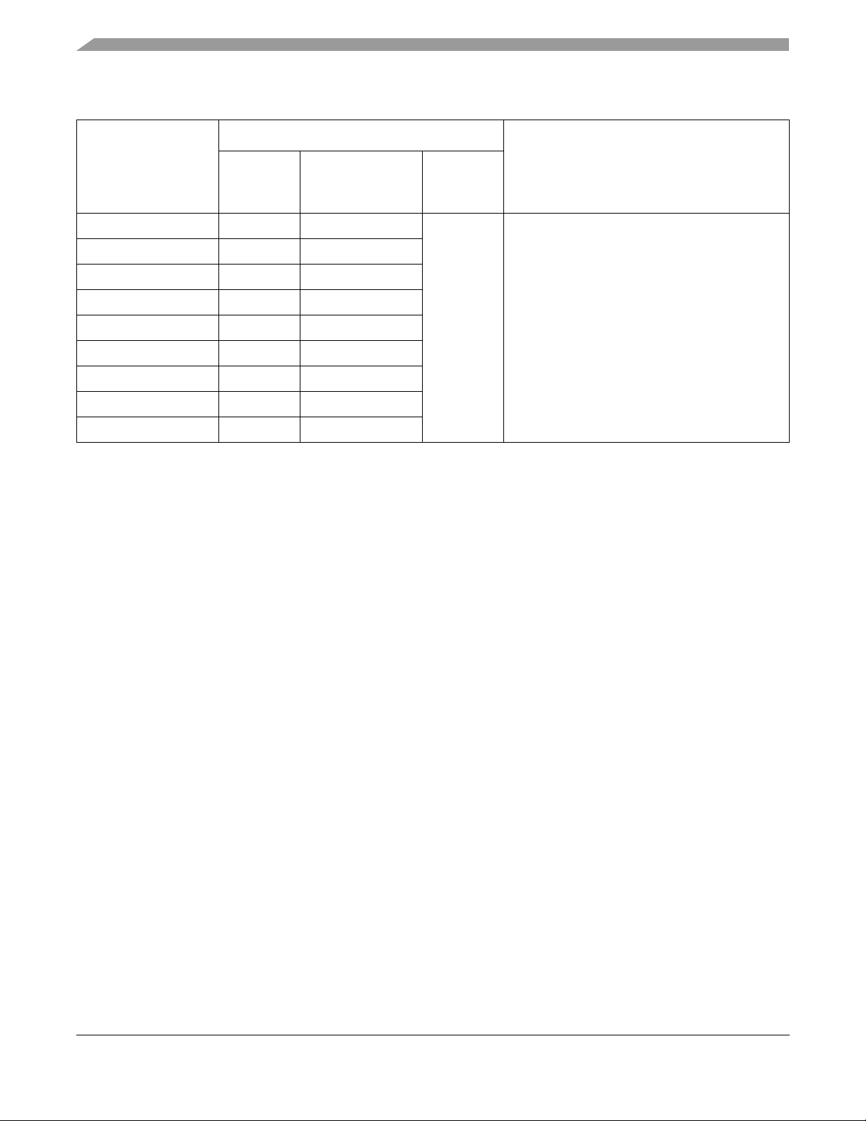
Table A. Part Numbers Addressed by This Data Sheet
Operating Conditions
Freescale
Part Number
MC7448THX1000Nx 1000 1.0 V ± 50 mV –40 to 105 Modified core frequency and voltage to reduce
MC7448THX1267NC 1267 1.1 V ± 50 mV
MC7448THX1267ND 1267 1.05 V ± 50 mV
MC7448THX1400Nx 1400 1.15 V ± 50 mV
MC7448THX1700LD 1700 1.3 V +20/-50 mV
PPC7448THX1000Nx
PPC7448THX1267NC
PPC7448THX1267ND
PPC7448THX1400Nx
Note:
1. The P prefix in a Freescale part number designates a “Pilot Production Prototype” as defined by Freescale SOP 3-13. These
parts have only preliminary reliability and characterization data. Before pilot production prototypes can be shipped, written
authorization from the customer must be on file in the applicable sales office acknowledging the qualification status and the
fact that product changes may still occur as pilot production prototypes are shipped.
2See Section 5.1, “DC Electrical Characteristics,” for information regarding V
CPU
Frequency
(MHz)
1
1000 1.0 V ± 50 mV
1
1267 1.1 V ± 50 mV
1
1267 1.05 V ± 50 mV
1
1400 1.15 V ± 50 mV
T
V
DD
2
2
j
(•C)C)
power consumption, extended operating
temperature.
Significant Differences from
Hardware Specifications
specifications for 1400 MHz device.
DD
4 General Parameters
Core power supply 1.3 V (1700L MHz revision level D devices)
1.15 V (1400N MHz devices)
1.1 V (1267N MHz revision level C devices)
1.05 V (1267N MHz revision level D devices)
1.0 V (1000N MHz devices)
Note: See Section 5.1, “DC Electrical Characteristics,” for information regarding VDD
specifications for 1400 MHz device.
5.1 DC Electrical Characteristics
Table 4 provides the recommended operating conditions for the MPC7448 part numbers described here.
NOTE
Table 4 describes the nominal operating conditions of the device. For
information on the operation of the device at supported derated core voltage
conditions, see Section 5.3, “Voltage and Frequency Derating.”
MPC7448 Hardware Specifications Addendum for the MC7448Txxnnnnmx Series, Rev. 2
2 Freescale Semiconductor
General Parameters
Table 4. Recommended Operating Conditions
Recommended Value
Characteristic Symbol
1000N MHz
Core supply voltage V
PLL supply voltage AV
Die-junction temperature T
Notes:
1. These are the recommended and tested operating conditions. Some speed grades in addition support voltage derating; see
Section 5.3, “Voltage and Frequency Derating.” Proper device operation outside of these conditions and those specified in
Section 5.3, “Voltage and Frequency Derating,” is not guaranteed.
2. This voltage is the input to the filter discussed in Section 9.2.2, “PLL Power Supply Filtering,” in the hardware specifications
and not necessarily the voltage at the AV
3. VDD and AVDD may be reduced in order to reduce power consumption if further maximum core frequency constraints are
observed. See Section 5.3, “Voltage and Frequency Derating,” for specific information.
DD
DD
j
1.0 V
± 50 mV
1.0 V
± 50 mV
–40to105 –40to105 –40to105 –40to105 –40to105 •CC
DD
1267N MHz
Revision
Level C
1.1 V
± 50 mV
1.1 V
± 50 mV
pin, which may be reduced from VDD by the filter.
3
1267N MHz
Revision
Level D
± 50 mV
± 50 mV
1.05 V
1.05 V
3
1
1400N MHz31700L MHz
1.15 V
± 50 mV
1.15 V
± 50 mV
1.3 V
+20/-50 mV
1.3 V
+20/-50 mV
Unit Notes
V
V2
Table 7 provides the power consumption for the MPC7448 part numbers described by this document; see
Section 11.1, “Part Numbers Addressed by This Specification,” for more information. The MPC7448
RISC Microprocessor Hardware Specifications presents guidelines on the use of these parameters for
system design. For information on power consumption when dynamic frequency switching is enabled, see
Section 9.8.5, “Dynamic Frequency Switching (DFS),” in the hardware specifications.
The power consumptions provided in Table 7 represent the power consumption of each speed grade when
operated at the rated maximum core frequency (see Table 8). Freescale sorts devices by power as well as
by core frequency, and power limits for each speed grade are independent of each other. Each device is
tested at its maximum core frequency only. (Note that Deep Sleep Mode power consumption is
independent of clock frequency.) Operating a device at a frequency lowe r than its rated maximum is fully
supported provided the clock frequencies are within the specifications given in Table 8, and a device
operated below its rated maximum will have lower power consumption. However, inferences should not
be made about a device’ s power consumption based on the power specifications of another (lower) speed
grade. For example, a 1400 MHz device operated at 1267 MHz will not exhibit the same power
consumption as a 1267 MHz device operated at 1267 MHz.
NOTE
The power consumption information in this table applies when the device
operates at the nominal core voltage indicated in Table 4. For power
consumption at derated core voltage conditions, see Section 5.3, “Voltage
and Frequency Derating.”
MPC7448 Hardware Specifications Addendum for the MC7448Txxnnnnmx Series, Rev. 2
Freescale Semiconductor 3

General Parameters
Table 7. Power Consumption for MPC7448 at Maximum Rated Frequency
Die
Junction
(Tj) (•C)C)
Typical 65 9.5 8.4 11.0 21.0 W 1, 2
Thermal 105 12.0 10.3 13.7 25.6 W 1, 5
Maximum 105 13.9 12.0 15.9 29.8 W 1, 3
Typical 105 6.5 6.5 8.3 13.0 W 1, 6
Typical 105 6.3 6.3 8.0 12.5 W 1, 6
Deep Sleep Mode (PLL Disabled)
Typical 105 6.0 6.0 7.7 12.0 W 1, 6
Notes:
1. These values specify the power consumption for the core power supply (V
processor bus frequencies and configurations. The values do not include I/O supply power (OV
). OVDD power is system dependent but is typically < 5% of VDD power. Worst case power consumption for
(AV
DD
AV
<13mW.
DD
2. Typical nominal power consumption is an average value measured at the nominal recommended V
65°C while running the Dhrystone 2.1 benchmark and achieving 2.3 Dhrystone MIPs/MHz. This parameter is not 100%
tested but periodically sampled.
3. Maximum power consumption is the average measured at nominal VDD and maximum operating junction temperature (see
Ta bl e 4) while running an entirely cache-resident, contrived sequence of instructions to keep all the execution units
maximally busy.
4. Doze mode is not a user-definable state; it is an intermediate state between full-power and either nap or sleep mode. As a
result, power consumption for this mode is not tested.
5. Typical thermal power consumption is an average value measured at the nominal recommended V
105°C while running the Dhrystone 2.1 benchmark and achieving 2.3 Dhrystone MIPs/MHz. This parameter is not 100%
tested but periodically sampled.
6. Typical power consumption for these modes is measured at the nominal recommended V
mode described. This parameter is not 100% tested but is periodically sampled.
7. Power consumption for the 1267 MHz device is intentionally constrained via testing and sorting to assure low power
consumption for this device.
Maximum Processor Core Frequency
(Speed Grade, MHz)
1000N 1267N
Full-Power Mode
Nap Mode
Sleep Mode
7
1400N 1700L
) at nominal voltage and apply to all valid
DD
Unit Notes
) or PLL supply power
DD
(see Ta bl e 4) and
DD
(see Ta bl e 4) and
DD
(see Ta b l e 4 ) and 105°C in the
DD
5.2.1 Clock AC Specifications
Table 8 provides the clock AC timing specifications for the MPC7448 part numbers discussed here.
NOTE
The core frequency information in this table applies when the device
operates at the nominal core voltage indicated in Table 4. For core
frequency specifications at derated core voltage conditions, see Section 5.3,
“Voltage and Frequency Derating.”
MPC7448 Hardware Specifications Addendum for the MC7448Txxnnnnmx Series, Rev. 2
4 Freescale Semiconductor

Table 8. Clock AC Timing Specifications
At recommended operating conditions. See Ta bl e 4 .
General Parameters
Maximum Processor Core Frequency (MHz)
Characteristic Symbol
Min Max Min Max Min Max Min Max
Processor frequency
DFS mode disabled
Processor frequency
DFS mode enabled
VCO frequency f
Notes:
1. Caution: The SYSCLK frequency and PLL_CFG[0:5] settings must be chosen such that the resulting SYSCLK (bus)
frequency, processor core frequency, and PLL (VCO) frequency do not exceed their respective maximum or minimum
operating frequencies. Refer to the PLL_CFG[0:5] signal description in Section 9.1.1, “PLL Configuration,” in the hardware
specifications for valid PLL_CFG[0:5] settings.
8. This reflects the maximum and minimum core frequencies when the dynamic frequency switching feature (DFS) is disabled.
f
core_DFS
9. Caution: These values specify the maximum processor core and VCO frequencies when the device is operated at the
nominal core voltage. If operating the device at the derated core voltage, the processor core and VCO frequencies must be
reduced. See Section 5.3, “Voltage and Frequency Derating,” for more information.
10.This specification supports the Dynamic Frequency Switching (DFS) feature and is applicable only when one of the DFS
modes (divide-by-2 or divide-by-4) is enabled. When DFS is disabled, the core frequency must conform to the maximum and
minimum frequencies stated for f
provides the maximum and minimum core frequencies in a DFS mode.
f
core
f
core_DFS
VCO
500 1000 500 1267 500 1400 600 1700 MHz 1, 8, 9
250 500 250 633 250 700 300 850 MHz 10
500 1000 500 1267 500 1400 600 1700 MHz 1, 9
.
core
Unit Notes1000N 1267N 1400N 1700L
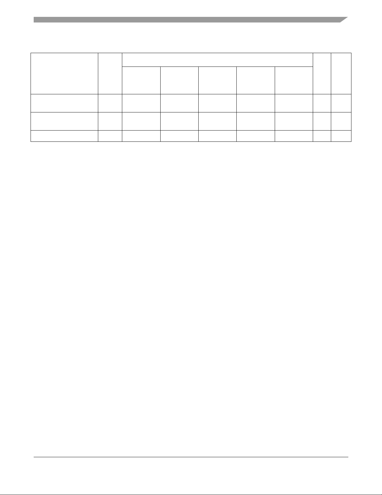
5.3 Voltage and Frequency Derating
To reduce power consumption, these devices support voltage and frequency derating in which the core
voltage (VDD) may be reduced if the reduced maximum processor core frequency requirements are
observed. The supported derated core voltage, resulting maximum processor core frequency (f
power consumption are provided in Table 11. Only those parameters in Table 11 are affected; all other
parameter specifications are unaffected.
Table 11. Supported Voltage, Core Frequency, and Power Consumption Derating
Maximum Rated
Core Frequency
(Device Marking)
1000N N/A
1267N 1.0 V ± 50 mV 1000 MHz 6.0 W 7.3 W 8.5 W
1400N 1.0 V ± 50 mV 1000 MHz 8.0 W 9.9 W 11.5 W
1700L N/A
Supported
Derated Core
Voltage ( V
Maximum Derated
Core Frequency
)
DD
(f
core
Full-Power Mode Power Consumption
)
Typical Thermal Maximum
core
), and
MPC7448 Hardware Specifications Addendum for the MC7448Txxnnnnmx Series, Rev. 2
Freescale Semiconductor 5

Part Numbering and Marking
9.2 Power Supply Design and Sequencing
The power supply design and sequencing requirements of the devices described here are identical to those
described in the MPC7448 RISC Microprocessor Hardware Specifications.
11 Part Numbering and Marking
11.1 Part Numbers Addressed by This Specification
Table 17 provides the ordering information for the MPC7448 parts described in this document.
Table 17. Part Marking Nomenclature
xx
Product
Code
MC
PPC
MC 1700 L: 1.3 V +20/-50 mV
Notes:
1. The P prefix in a Freescale part number designates a “Pilot Production Prototype” as defined by Freescale SOP 3-13. These
parts have only preliminary reliability and characterization data. Before pilot production prototypes can be shipped, written
authorization from the customer must be on file in the applicable sales office acknowledging the qualification status and the
fact that product changes may still occur as pilot production prototypes are shipped.
7448 T
Part
Identifier
7448 T = Extended
1
Specification
Modifier
Temperature
Device
xx nnnn
Package
HX = HCTE BGA 1000 N: 1.0 V ± 50 mV
Processor
Frequency
1267
Revision C only
1267
Revision D only
1400 N: 1.15 V ± 50 mV
Application Modifier Revision Level
N: 1.1 V ± 50 mV
N: 1.05 V ± 50 mV
m
– 40 to 105 °C
– 40 to 105 °C
– 40 to 105 °C
– 40 to 105 °C
– 40 to 105 °C
x
C: 2.1: PVR = 0x8004_0201
D: 2.2: PVR = 0x8004_0202
D:2.2: PVR = 0x8004_0202
MPC7448 Hardware Specifications Addendum for the MC7448Txxnnnnmx Series, Rev. 2
6 Freescale Semiconductor

11.3 Part Marking
Parts are marked as the example shown in Figure 23.
xx7448T
xxnnnnmx
AWLYYWW
MMMMMM
YWWLAZ
7448
Notes:
AWLYYWW is the test code, where YYWW is the date code (YY = year, WW = work week)
MMMMMM is the M00 (mask) number.
YWWLAZ is the assembly traceability code.
Figure 23. Part Marking for BGA Device
BGA
Document Revision History
Document Revision History
Table B provides a revision history for this part number specification.
Table B. Document Revision History
Revision Date Substantive Change(s)
2 04/2007 Added 1700LD device information.
On first page changed title part number from being N application modifier specific (MC7448TxxxnnnnNx)
to generic MC7448Txxnnnnmx.
On first page under Freescale Part Numbers Affected added MC7448THX1700LD.
Ta bl e A : Added a 1700L MHz revision D row.
Section 4, “General Parameters”: Added 1700L MHz revision level D information and added N application
modifier information to the 1000, 1267, and 1400 devices.
Ta bl e 4, Ta b l e 7 , and Ta bl e 8: Added 1700L columns.
Ta bl e 4, Ta b l e 7 , Ta b l e 8 , and Ta bl e 1 1 : Added added N application modifier information to the 1000,
1267, and 1400 column headings.
Ta bl e 11 : Added 1700L row.
Ta bl e 17 : Changed ‘N’ application modifier at top of table to generic ‘m’. Added 1700L information for
revision level D.
Figure 23: Updated part marking replacing ‘N’ application modifier with ‘m’.
1 10/2006 Added revision level D device information.
On first page under Freescale Part Numbers Affected added PPC7448THX1000Nx,
PPC7448THX1267Nx, and PPC7448THX1400Nx.
Ta bl e A and list on first page: x stands for C or D revision level.
Ta bl e A : Added 1267 MHz revision D row and 4 PPC part number rows.
Section 4, “General Parameters”: Added 1267 MHz revision level D information.
Ta bl e 4: Added 1267 MHz revision D only column.
Ta bl e 17 : Added PVR and 1267 information for revision level D, added PPC product code, and footnote 1.
0 6/2006 Initial release.
MPC7448 Hardware Specifications Addendum for the MC7448Txxnnnnmx Series, Rev. 2
Freescale Semiconductor 7

How to Reach Us:
Home Page:
www.freescale.com
email:
support@freescale.com
USA/Europe or Locations Not Listed:
Freescale Semiconductor
Technical Information Center, CH370
1300 N. Alma School Road
Chandler, Arizona 85224
1-800-521-6274
480-768-2130
support@freescale.com
Europe, Middle East, and Africa:
Freescale Halbleiter Deutschland GmbH
Technical Information Center
Schatzbogen 7
81829 Muenchen, Germany
+44 1296 380 456 (English)
+46 8 52200080 (English)
+49 89 92103 559 (German)
+33 1 69 35 48 48 (French)
support@freescale.com
Japan:
Freescale Semiconductor Japan Ltd.
Headquarters
ARCO Tower 15F
1-8-1, Shimo-Meguro, Meguro-ku
Tokyo 153-0064, Japan
0120 191014
+81 3 5437 9125
support.japan@freescale.com
Asia/Pacific:
Freescale Semiconductor Hong Kong Ltd.
Technical Information Center
2 Dai King Street
Tai Po Industrial Estate,
Tai Po, N.T., Hong Kong
+800 2666 8080
support.asia@freescale.com
For Literature Requests Only:
Freescale Semiconductor
Literature Distribution Center
P.O. Box 5405
Denver, Colorado 80217
1-800-441-2447
303-675-2140
Fax: 303-675-2150
LDCForFreescaleSemiconductor
@hibbertgroup.com
Information in this document is provided solely to enable system and software
implementers to use Freescale Semiconductor products. There are no express or
implied copyright licenses granted hereunder to design or fabricate any integrated
circuits or integrated circuits based on the information in this document.
Freescale Semiconductor reserves the right to make changes without further notice to
any products herein. Freescale Semiconductor makes no warranty, representation or
guarantee regarding the suitability of its products for any particular purpose, nor does
Freescale Semiconductor assume any liability arising out of the application or use of
any product or circuit, and specifically disclaims any and all liability, including without
limitation consequential or incidental damages. “Typical” parameters which may be
provided in Freescale Semiconductor data sheets and/or specifications can and do
vary in different applications and actual performance may vary over time. All operating
parameters, including “Typicals” must be validated for each customer application by
customer’s technical experts. Freescale Semiconductor does not convey any license
under its patent rights nor the rights of others. Freescale Semiconductor products are
not designed, intended, or authorized for use as components in systems intended for
surgical implant into the body, or other applications intended to support or sustain life,
or for any other application in which the failure of the Freescale Semiconductor product
could create a situation where personal injur y or death may occur. Should Buyer
purchase or use Freescale Semiconductor products for any such unintended or
unauthorized application, Buyer shall indemnify and hold Freescale Semiconductor
and its officers, employees, subsidiaries, affiliates, and distributors harmless against all
claims, costs, damages, and expenses, and reasonable attorney fees arising out of,
directly or indirectly, any claim of personal injury or death associated with such
unintended or unauthorized use, even if such claim alleges that Freescale
Semiconductor was negligent regarding the design or manufacture of the par t.
Freescale™ and the Freescale logo are trademarks of Freescale Semiconductor, Inc.
The Power Architecture and Power.org word marks and the Power and Power.org logos
and related marks are trademarks and service marks licensed by Power.org. The
described product is a PowerPC microprocessor. The PowerPC name is a trademark
of IBM Corp. and is used under license. All other product or service names are the
property of their respective owners.
© Freescale Semiconductor, Inc., 2007.
Document Number: MPC7448ECS02AD
Rev. 2
04/2007
 Loading...