

Datasheet MPC7410RX400NE, MPC7410HX400NE, MPC7410VS400NE, MC7410VU400NE, MPC7410RX450NE Datasheet (Freescale)
...
查询MC7410VU400NE供应商
Freescale Semiconductor
Advance Information
Document Number: MPC7410ECS02AD
Rev. 2.0, 11/2007
--- Preliminary ---
MPC7410 RISC Microprocessor
Hardware Specifications Addendum
for the MPC7410
This document describes part number-specific changes to
recommended operating conditions and revised electrical
specifications, as applicable, from those described in the
general MPC7410 Har dwar e Specifications (Document No.
MPC7410EC).
Specifications provided in this document supersede those in
the MPC7410 Har dware Specifications, for the part numbers
listed in Table A only. Specifications not addressed herein
are unchanged. Because this document is frequently
updated, refer to http://www.freescale.com or to your
Freescale sales office for the lates t version.
xxnnn
NE Series
Freescale Part Numbers Affected:
MPC7410RX400NE
MPC7410HX400NE
MPC7410VS400NE
MC7410VU400NE
MPC7410RX450NE
MPC7410HX450NE
MPC7410VS450NE
MC7410VU450NE
Note that headings and table numbers in this document are
not consecutively numbered. They are intended to
correspond to the heading or table affected in the general
hardware specification. Part numbers addressed in this
document are listed in Table A. For more detailed ordering
information see Table 17.
This document contains information on a new product. Specifications and information herein
are subject to change without notice.
© Freescale Semiconductor, Inc., 2002, 2007. All rights reserved.
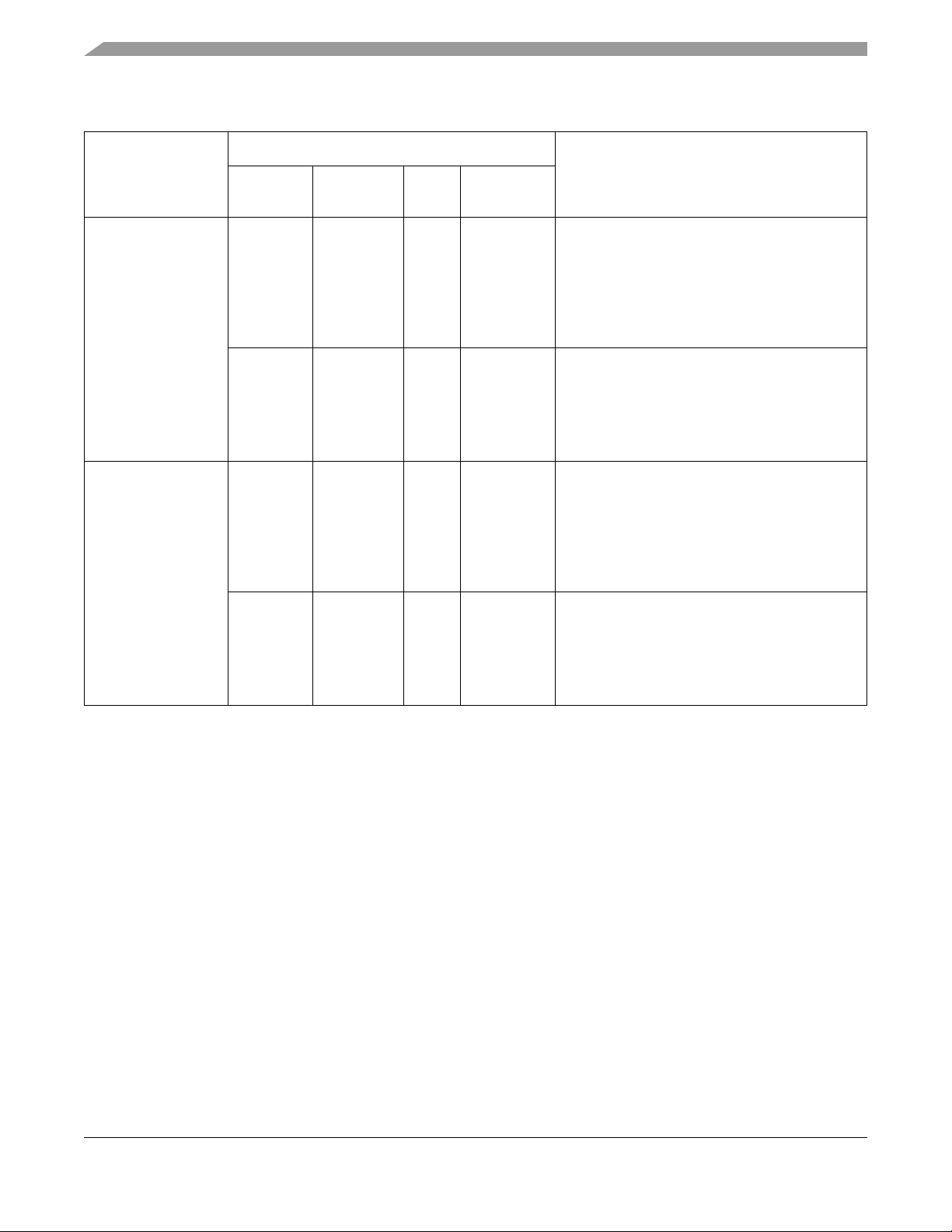
Features
Freescale Part
Number
Table A. Part Numbers Addressed by this Data Sheet
Frequency
Operating Conditions
Vdd T
(°C) OVdd
J
Significant Differences from Hardware
SpecificationCPU
MPC7410RX400NE
MPC7410HX400NE
MPC7410VS400NE
MC7410VU400NE
MPC7410RX450NE
MPC7410HX450NE
MPC7410VS450NE
MC7410VU450NE
400 MHz 1.5V±50mV 0 to
105
450 MHz 1.8V
±100mV
450 MHz 1.5V±50mV 0 to
500 MHz 1.8V
±100mV
0 to
105
105
0 to
105
1.8/2.5 V Reduced core voltage to achieve lower power
consumption. Removes 3.3V OVdd support. For
all AC/DC specifications not mentioned in this
document, please refer to the
MPC7410(RX/HX/VS)400LE and
MC7410VU400LE specifications in the general
MPC7410 Hardware Specifications
1.8/2.5/3.3 V The MPC7410(RX/HX/VS)400NE and
MC7410VU400NE also fully conform to the
MPC7410(RX/HX/VS)450LE and
MC7410VU450LE specifications, respectively.
Refer to the general
Specifications
1.8/2.5 V Reduced core voltage to achieve lower power
consumption. Removes 3.3V OVdd support. For
all AC/DC specifications not mentioned in this
document, please refer to the
MPC7410(RX/HX/VS)450LE and
MC7410VU450LE specifications in the general
MPC7410 Hardware Specifications
1.8/2.5/3.3 V The MPC7410(RX/HX/VS)450NE and
MC7410VU400NE also fully conform to the
MPC7410(RX/HX/VS)500LE and
MC7410VU500LE specifications, respectively.
Refer to the general
Specifications
MPC7410 Hardware
.
MPC7410 Hardware
.
.
.
2 Features
This section summarizes changes to the features of the MPC7410 described in the MPC7410 Hardware
Specifications.
• Bus interface
— Selectable interface voltages of 1.8 V, 2.5 V (3.3 V not supported)
4.1 DC Electrical Characteristics
Voltage to the L2 I/Os and processor interface I/Os are provided through separate sets of supply pins and
may be provided at the voltages shown in Table 2.
MPC7410 RISC Microprocessor Hardware Specifications Addendum for the MPC7410xxnnnNE Series, Rev. 2.0
2 Freescale Semiconductor
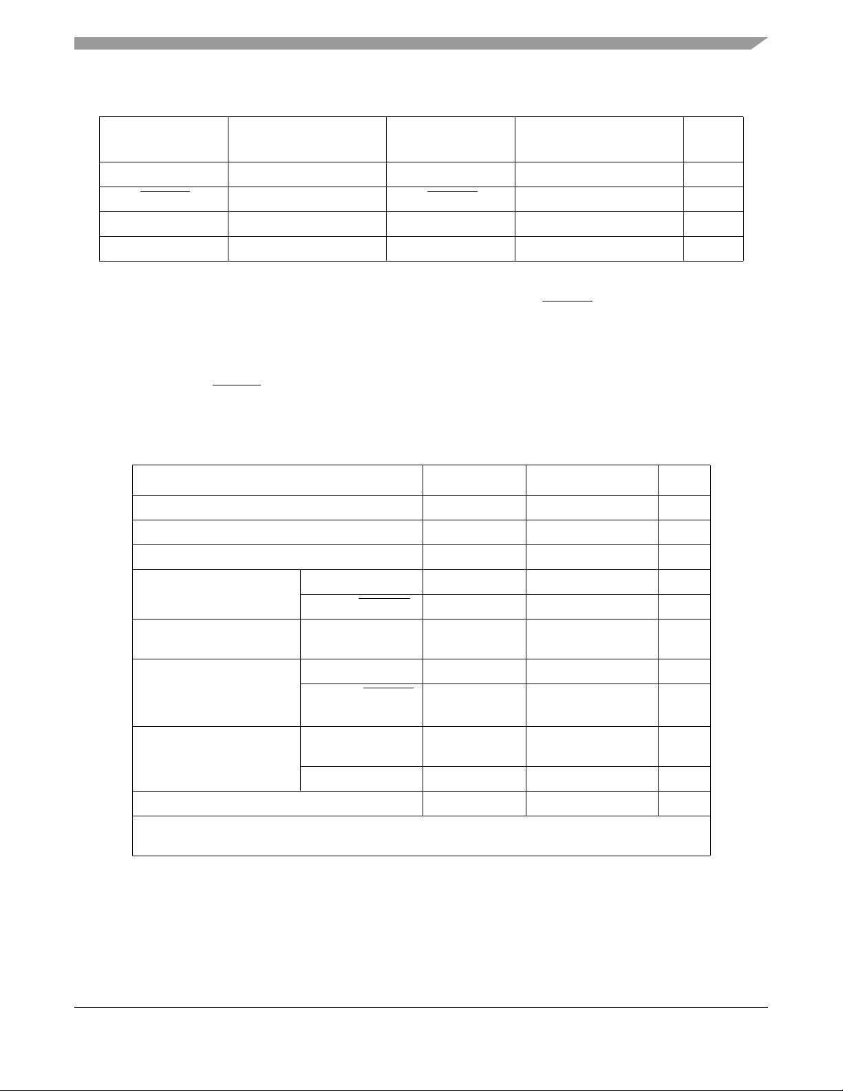
Table 2. Input Threshold Voltage Setting
Features
BVSEL Signal
3
Processor Bus Input
Threshold is Relative to:
L2VSEL Signal
L2 Bus Input Threshold is
3
Relative to:
Note
0 1.8 V 0 1.8 V 1
HRESET
2.5 V HRESET 2.5 V 1, 2
1 Not Supported 1 2.5 V 1, 4, 5
HRESET Not Supported HRESET Not Supported —
Notes:
1. Caution: The input threshold selection must agree with the OVdd/L2OVdd voltages supplied.
2. To select the 2.5-V threshold option, BVSEL and/or L2VSEL should be tied to HRESET
so that the two signals
change state together. This is the preferred method for selecting this mode of operation.
3. To overcome the internal pull-up resistance, a pull-down resistance less than 250 ohms should be used.
4. Default voltage setting if left unconnected (internal pulled-up).
5. Caution: The XPC7410RXnnnNE does not support the default OVdd setting of 3.3 V. The BVSEL input must be tie
either low or to HRESET
.
T able 3 provides the recommended operating conditions for the MPC7410 part numbers described herein.
Table 3. Recommended Operating Conditions
Characteristic Symbol Recommended Value Unit
Core supply voltage Vdd 1.5V ± 50mV V
PLL supply voltage AVdd 1.5V ± 50mV V
L2 DLL supply voltage L2AVdd 1.5V ± 50mV V
Processor bus supply voltage BVSEL = 0 OVdd 1.8V ± 100mV V
BVSEL = HRESET
BVSEL = HRESET
OVdd 2.5V ± 100mV V
OVdd Not Supported V
or BVSEL = 1
L2 bus supply voltage L2VSEL = 0 L2OVdd 1.8V ± 100mV V
L2VSEL = HRESET
L2OVdd 2.5V ± 100mV V
or L2VSEL = 1
Input voltage Processor bus and
V
in
GND to OVdd V
JTAG Signals
L2 Bus V
Die-junction temperature T
in
j
GND to L2OVdd V
0 to 105 °C
Note: These are the recommended and tested operating conditions. Proper device operation outside of
these conditions is not guaranteed.
MPC7410 RISC Microprocessor Hardware Specifications Addendum for the MPC7410xxnnnNE Series, Rev. 2.0
Freescale Semiconductor 3

Features
Table 7 provides the power consumption for the MPC7410 part at the frequencies described herein.
Table 7. Power Consumption for MPC7410
Processor
(CPU)
Frequency
400Mhz 450Mhz
Full-On Mode
Ty p i ca l
Maximum
Doze Mode
Maximum 3.6 4.1 W 1, 2
Nap Mode
Maximum 1.35 1.5 W 1, 2
Sleep Mode
Maximum 1.3 1.45 W 1, 2
Sleep Mode—PLL and DLL Disabled
Typical 0.6 0.6 W 1, 3
Maximum 1.1 1.1 W 1, 2
Notes:
1. These values apply for all valid processor bus and L2 bus ratios. The values
do not include I/O Supply Power (OVdd and L2OVdd) or PLL/DLL supply
power (AVdd and L2AVdd). OVdd and L2OVdd power is system dependent,
but is typically <10% of Vdd power. Worst case power consumption for AVdd
= 15 mw and L2AVdd = 15 mW.
2. Maximum power is measured at 105 °C and Vdd = 1.5V while running an
entirely cache-resident, contrived sequence of instructions which keep the
execution units, including AltiVec, maximally busy.
3. Typical power is an average value measured at 65 °C and Vdd = 1.5V in a
system while running typical benchmarks.
2.92 3.29 W 1, 3
6.6 7.43 W 1, 2,
Processor
(CPU)
Frequency Unit Notes
MPC7410 RISC Microprocessor Hardware Specifications Addendum for the MPC7410xxnnnNE Series, Rev. 2.0
4 Freescale Semiconductor

Document Revision History
9 Document Revision History
Table 16 provides a revision history for this Hardware Specification Addendum.
Table 16. Document Revision History
Revision Date Substantive Changes
2.0 11/16/2007 Updated document title to remove “RX” from part number since other non-RX package devices
were added to this specification.
Added MPC7410HX400NE, MPC7410VS400NE, MC7410VU400NE, MPC7410HX450NE,
MPC7410VS450NE, and MC7410VU450NE devices to list on cover page and to Table A.
Updated Table 17 to match corresponding table in
1.1 04/19/2005 Document template update
Document ID change from MPC7410RXNEPNS for Part Number Specification to
MPC7410ECS02AD for Hardware Specification Addendum.
1 10/2002 Minor formatting.
Added Section 1.9 Document Revision History.
Section 1.10.1 - added Table 17 - Part Marking Nomenclature.
0 Initial release
MPC7410 Hardware Specifications
MPC7410 RISC Microprocessor Hardware Specifications Addendum for the MPC7410xxnnnNE Series, Rev. 2.0
Freescale Semiconductor 5

Ordering Information
BGA
Notes
:
CCCCC is the country of assembly (this space is left blank if parts are assembled in the United States)
MMMMMM is the 6-digit mask number
ATWLYYWWA is the tr ac ea b ility cod e
MPC7410
RXnnnNE
MMMMMM
ATWLYYWWA
7410
nnn is the speed grade of the part
10 Ordering Information
10.1 Part Numbers Addressed by this Specification
Table 17 provides the ordering information for the MPC7410 part described in this document.
Table 17. Part Marking Nomenclature.
Mxx 7410 xx
Product
Code
MPC 7410 RX = CBGA 400
MC VU = HCTE_CBGA
Notes:
1. Processor core frequencies supported by parts are addressed by this specification only. Parts addressed by other
specifications may support other maximum core frequencies.
Par t
Identifier
Package
HX = HCTE_CBGA
VS = HCTE_LGA
(Lead Free C5 Solder
Spheres)
nnn
Processor
Frequency
450
500
400
450
NE
Application
1
Modifier
N: 1.5 V ± 50 mV
0 to 105 °C
Revision Level
E: 1.4; PVR = 800C 1104
10.3 Part Marking
Parts are marked as the example shown in Figure 26.
Figure 26. Freescale Part Marking for BGA Device
MPC7410 RISC Microprocessor Hardware Specifications Addendum for the MPC7410xxnnnNE Series, Rev. 2.0
6 Freescale Semiconductor

THIS PAGE INTENTIONALLY LEFT BLANK
Ordering Information
MPC7410 RISC Microprocessor Hardware Specifications Addendum for the MPC7410xxnnnNE Series, Rev. 2.0
Freescale Semiconductor 7

How to Reach Us:
Home Page:
www.freescale.com
email:
support@freescale.com
USA/Europe or Locations Not Listed:
Freescale Semiconductor
Technical Information Center, CH370
1300 N. Alma School Road
Chandler, Arizona 85224
(800) 521-6274
480-768-2130
support@freescale.com
Europe, Middle East, and Africa:
Freescale Halbleiter Deutschland GmbH
Technical Information Center
Schatzbogen 7
81829 Muenchen, Germany
+44 1296 380 456 (English)
+46 8 52200080 (English)
+49 89 92103 559 (German)
+33 1 69 35 48 48 (French)
support@freescale.com
Japan:
Freescale Semiconductor Japan Ltd.
Headquarters
ARCO Tower 15F
1-8-1, Shimo-Meguro, Meguro-ku
Tokyo 153-0064, Japan
0120 191014
+81 2666 8080
support.japan@freescale.com
Asia/Pacific:
Freescale Semiconductor Hong Kong Ltd.
Technical Information Center
2 Dai King Street
Tai Po Industrial Estate,
Tai Po, N.T., Hong Kong
+800 2666 8080
support.asia@freescale.com
For Literature Requests Only:
Freescale Semiconductor
Literature Distr ibution Center
P.O. Box 5405
Denver, Colorado 80217
(800) 441-2447
303-675-2140
Fax: 303-675-2150
LDCForFreescaleSemiconductor
@hibbertgroup.com
Information in this document is provided solely to enable system and software
implementers to use Freescale Semiconductor products. There are no express or
implied copyright licenses granted hereunder to design or fabricate any integrated
circuits or integrated circuits based on the information in this document.
Freescale Semiconductor reserves the right to make changes without further notice to
any products herein. Freescale Semiconductor makes no warranty, representation or
guarantee regarding the suitability of its products for any part icular purpose, nor does
Freescale Semiconductor assume any liability arising out of the application or use of
any product or circuit, and specifically disclaims any and all liability, including without
limitation consequential or incidental damages. “Typical” parameters which may be
provided in Freescale Semiconductor data sheets and/or specifications can and do
vary in different applications and actual performance may vary over time. All operating
parameters, including “Typicals” must be validated for each customer application by
customer’s technical experts. Freescale Semiconductor does not convey any license
under its patent rights nor the rights of others. Freescale Semiconductor products are
not designed, intended, or authorized for use as components in systems intended for
surgical implant into the body, or other applications intended to support or sustain life,
or for any other application in which the failure of the Freescale Semiconductor product
could create a situation where personal injury or death may occur. Should Buyer
purchase or use Freescale Semiconductor products for any such unintende d or
unauthorized application, Buyer shall indemnify and hold Freescale Semiconductor
and its officers, employees, subsidiaries, affiliates, and distributors harmless against all
claims, costs, damages, and expenses, and reasonable attor ney fees arising out of,
directly or indirectly, any claim of personal injury or death associated with such
unintended or unauthorized use, even if such claim alleges that Freescale
Semiconductor was negligent regarding the design or manufacture of th e part.
Freescale™ and the Freescale logo are trademarks of Freescale Semiconductor, Inc.
All other product or service names are the proper ty of their respective owners. The
Power Architecture and Power.org word marks and the Power and Power.org logos and
related marks are trademarks and service marks licensed by Power.org.
© Freescale Semiconductor, Inc., 2002, 2007. Printed in the United States
of America. All rights reserved.
Document Number: MPC7410ECS02AD
Rev. 2.0
11/2007
 Loading...