

Page 1

EVBQE128
Evaluation Board
for Freescale
Flexis QE128
User’s Manual
Page 2

Page 3

EVBQE128
Evaluation Board
for Freescale
Flexis QE128 Microcontrollers
(80-Pin LQFP)
User’s Manual
Revision 1.1
Copyright © 2007 SofTec Microsystems
DC01355
®
Page 4
We want your feedback!
SofTec Microsystems is always on the look-out for new ways to improve its Products and
Services. For this reason feedback, comments, suggestions or criticisms, however small,
are always welcome.
Our policy at SofTec Microsystems is to comply with all applicable worldwide safety and
EMC/EMI regulations. Our products are certified to comply to the European New
Approach Directives and the CE mark is applied on all our products.
SofTec Microsystems
E-mail (general information): info@softecmicro.com
E-mail (technical support): support@softecmicro.com
Web: http://www.softecmicro.com
Important
SofTec Microsystems reserves the right to make improvements to this product, its documentation and software routines,
without notice. Information in this manual is intended to be accurate and reliable. However, SofTec Microsystems assumes no
responsibility for its use; nor for any infringements of rights of third parties which may result from its use.
SOFTEC MICROSYSTEMS WILL NOT BE LIABLE FOR DAMAGES RESULTING FROM LOSS OF DATA, PROFITS, USE
OF PRODUCTS, OR INCIDENTAL OR CONSEQUENTIAL DAMAGES, EVEN IF ADVISED OF THE POSSIBILITY
THEREOF.
Trademarks
SofTec Microsystems™ and the SofTec Microsystems logo are trademarks of SofTec Microsystems S.p.A.
Freescale™ and the Freescale logo are trademarks of Freescale Semiconductor, Inc.
Microsoft and Windows are trademarks or registered trademarks of Microsoft Corporation.
PC is a registered trademark of International Business Machines Corporation.
Other products and company names listed are trademarks or trade names of their respective companies.
This product as shipped from the factory has been verified to meet with requirements
FCC as a CLASS A product.
This product is designed and intended for use as a development platform for hardware or
software in an educational or professional laboratory.
In a domestic environment, this product may cause radio interference in which case the
user may be required to take adequate prevention measures.
Attaching additional wiring to this product or modifying the product operation from the
factory default as shipped may effect its performance and cause interference with other
apparatus in the immediate vicinity. If such interference is detected, suitable mitigating
measures should be taken.
Page 5

Contents
1 Introduction 5
1.1 Overview 5
1.2 Package Contents 5
1.3 Supported Devices 5
1.4 Recommended Reading 5
2 Hardware Features 7
2.1 Evaluation Board Features 7
2.2 microDART Interface 8
2.2.1 Hot Plug-In 9
3 Software Setup 11
3.1 Overview 11
3.2 Host System Requirements 11
3.3 Installing CodeWarrior Development Studio 11
4 Hardware Setup 13
4.1 First Connection 13
5 Operating Modes 17
5.1 Overview 17
5.2 Standalone Mode 17
5.3 Host Mode 18
EVBQE128 User's Manual
6 Application Tutorial 19
6.1 Overview 19
6.2 MC9S08QE128 Step-by-Step Tutorial 19
6.3 Converting the Example for the MCF51QE128 20
6.4 Additional Examples 21
7 Hot Plug-In 23
7.1 Overview 23
7.2 How to Enable Hot Plug-In 23
8 Jumper and Connector Settings 25
8.1 Jumpers 25
8.2 Connectors 28
Page 3
Page 6

Contents
9 Troubleshooting 31
9.1 USB Driver Problems 31
9.2 Communication Problems between the PC and the Demo Board 31
9.3 Problems with RS-232 Communication 31
Page 4
Page 7

EVBQE128 User's Manual
1 Introduction
1.1 Overview
The EVBQE128 Evaluation Board has been designed for the evaluation, demonstration and
debugging of the Freescale Flexis QE128 Microcontrollers (MC9S08QE128 and
MCF51QE128).
The EVBQE128 can be used as a standalone application or can be controlled by a host PC
via its built-in microDART™ interface.
1.2 Package Contents
The EVBQE128 package includes the following items:
The EVBQE128 evaluation board;
80-pin LQFP MC9S08QE128 and MCF51QE128 microcontrollers;
A USB cable;
A pick-up vacuum pump;
A universal, 12 V DC power supply;
System software DVD-ROM, including CodeWarrior™ Development Studio;
A Quick Start Guide sheet.
1.3 Supported Devices
The EVBQE128 Evaluation Board supports the following devices:
MC9S08QE128;
MCF51QE128;
And any other pin-to-pin compatible devices.
1.4 Recommended Reading
Freescale microcontroller-specific datasheets and application notes;
EVBQE128 Schematic.
Page 5
Page 8

Page 9

EVBQE128 User's Manual
2 Hardware Features
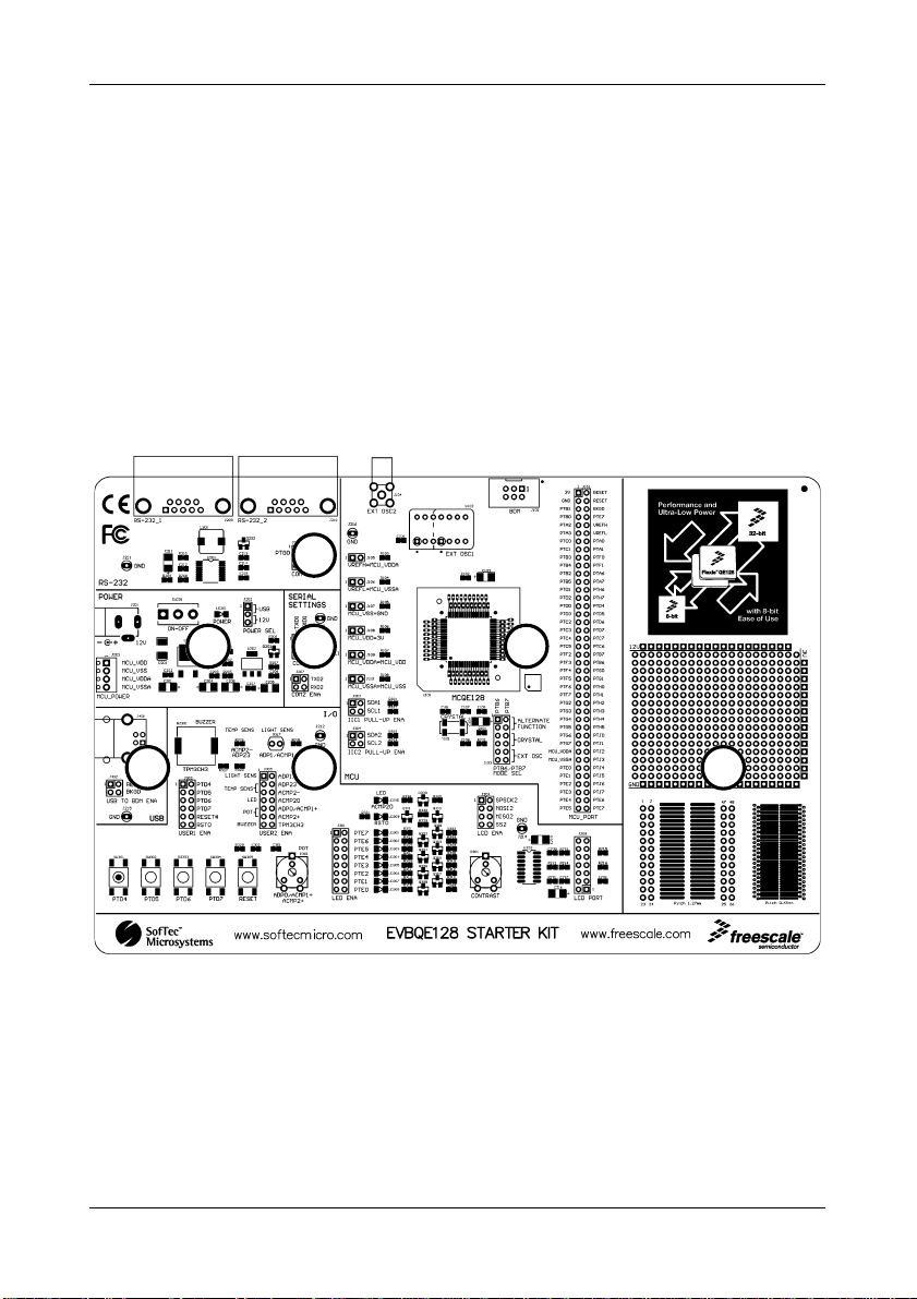
2.1 Evaluation Board Features
The EVBQE128 board features:
1. An “MCU” section containing:
An 80-pin LQFP socket accepting either the MC9S08QE128 or the MCF51QE128
microcontroller;
A crystal oscillator, a provision for a clock module, a provision for a connector for
providing an external clock source, together with jumpers to select the clock
source;
A BDM connector for in-circuit debugging/programming with an external
instrument;
A female header connectors with all of the MCU signals.
2. A power supply section containing:
A 12 V DC barrel input connector (2.1 mm);
A four-way micro terminal block for providing specific power supplies and voltage
references to the microcontroller;
A jumper to select the power supply source (USB bus or barrel connector);
A power on/off switch.
3. A built-in “microDART INTERFACE” section (with the main circuitry mounted on the
back of the board) which allows the host PC to communicate with the microcontroller
through a standard USB interface. Jumpers are present to configure this module.
Thanks to the microDART in-circuit debugging firmware, BDM commands are sent to
the target microcontroller through the USB bus. Additionally, a virtual COM port is
automatically available over the same USB connection. This virtual COM port can be
used by standard terminal programs, like HyperTerminal, to send/receive serial
characters to/from the target microcontroller.
4. An “I/O” section containing:
A Reset push-button;
Four additional push-button;
One potentiometer;
Eight dip-switches;
Page 7
Page 10
Hardware Features
A piezoelectric buzzer;
A light sensor;
A temperature sensor;
Ten user LEDs;
A circuitry for driving and external LCD;
A series of jumpers to connect/disconnect the above controls to/from the
microcontroller.
5. An “RS-232” section containing two RS-232 connectors together with a jumper to enable
the RS-232 communication.
6. A “SERIAL SETTINGS” section containing jumpers to select communication options.
7. A prototype area.
5
6
3 4
The EVBQE128 Evaluation Board
1 2
7
2.2 microDART Interface
Thanks to the microDART in-circuit debugging firmware, CodeWarrior can send BDM
commands to the target microcontroller through the USB bus.
Page 8
Page 11

EVBQE128 User's Manual
Additionally, when you plug the USB cable into the PC, a “virtual” COM port is automatically
created and, through this port, serial data can be transferred to/from the target microcontroller.
In other words, a terminal application such as HyperTerminal is able to use the virtual COM
port as if it were a normal COM port and send and receive characters normally.
This serial communication and BDM communication work simultaneously: CodeWarrior can be
used to work with the target microcontroller while HyperTerminal sends and receives
characters.
2.2.1 Hot Plug-In
The “Hot Plug-In” feature gives you the possibility to connect to a target microcontroller that is
running an application and to trace and debug the current running code without the need of a
complete erase and re-program of the flash memory.
Page 9
Page 12

Page 13

EVBQE128 User's Manual
3 Software Setup
3.1 Overview
Before connecting the Evaluation Board to the PC, it is recommended that you install
CodeWarrior first, so that the appropriate USB driver will be automatically found by Windows
when you connect the Evaluation Board.
3.2 Host System Requirements
The Evaluation Board is controlled by CodeWarrior Development Studio. The following
hardware and software are required to run the CodeWarrior user interface together with the
Evaluation Board:
A 200-MHz (or higher) PC compatible system running Windows 2000 or Windows XP;
128 MB of available system RAM plus 1 GB of available hard disk space;
A USB port;
DVD-ROM drive for installation.
3.3 Installing CodeWarrior Development Studio
To install the CodeWarrior Development Studio, insert the CodeWarrior DVD-ROM into your
computer’s DVD-ROM drive. A startup window will automatically appear. Follow the on-screen
instructions.
Page 11
Page 14

Page 15

EVBQE128 User's Manual
4 Hardware Setup
4.1 First Connection
The Evaluation Board is connected to a host PC through a USB port. Connection steps are
listed below in the recommended flow order:
1. Install all the required system software as described in the previous section.
2. Power the board through either the barrel connector or the USB connector, making sure
that the “POWER SEL” jumper selects the correct power source.
3. Make sure the “ON-OFF” switch is in the “ON” position. The “POWER” LED will turn on.
4. Insert one end of the USB cable into a free USB port of the PC.
5. Insert the other end of the USB cable into the USB connector on the Evaluation Board.
6. The first time the Evaluation Board is connected to the PC, Windows recognizes the
instrument and starts two separate “Found New Hardware Wizard” procedures: one
for the main USB driver and one for the USB virtual COM port driver.
7. The first “Found New Hardware Wizard” procedure asks you to specify the USB driver
to use for the instrument. On Windows XP (SP2) the following dialog box will appear.
Select the “No, not this time” option and click the “Next >” button.
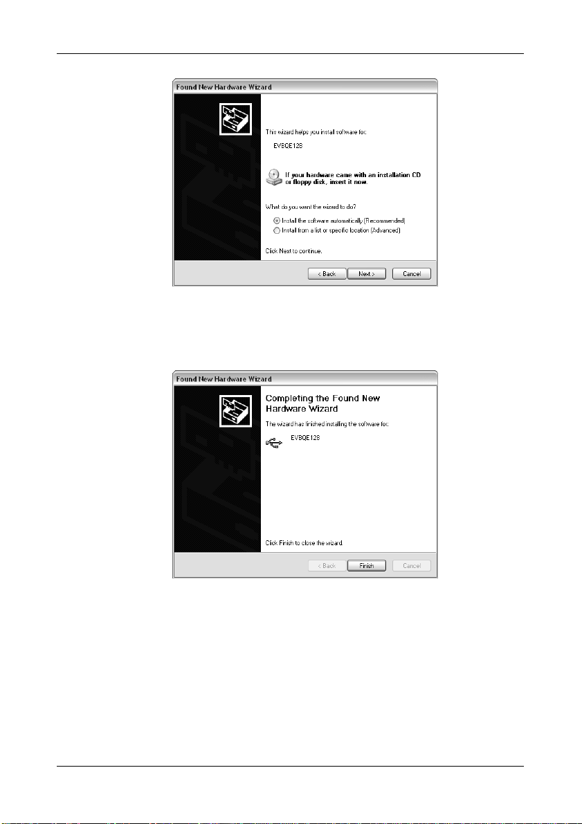
8. The following dialog box will appear.
Page 13
Page 16
Hardware Setup
Click the “Next >” button.
9. Windows will install the driver files to your system. At the end of the installation, the
following dialog box will appear.
Click the “Finish” button to exit from the “Found New Hardware Wizard” procedure.
10. The Evaluation Board’s main USB driver is now installed on your system.
11. The second “Found New Hardware Wizard” procedure asks you to specify the USB
virtual COM driver to use. On Windows XP (SP2) the following dialog box will appear.
Page 14
Page 17
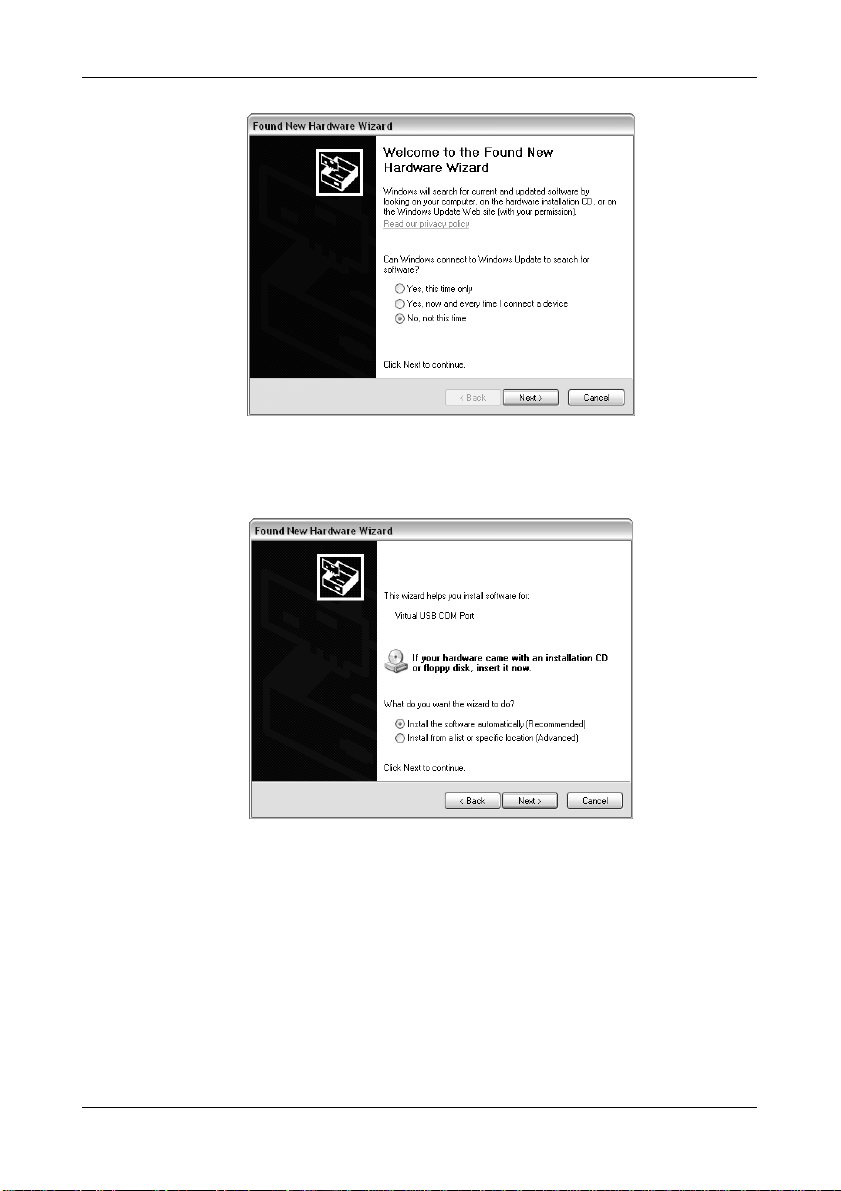
Select the “No, not this time” option and click the “Next >” button.
12. The following dialog box will appear.
EVBQE128 User's Manual
Click the “Next >” button.
13. Depending on your Windows settings, the following warning may appear.
Page 15
Page 18
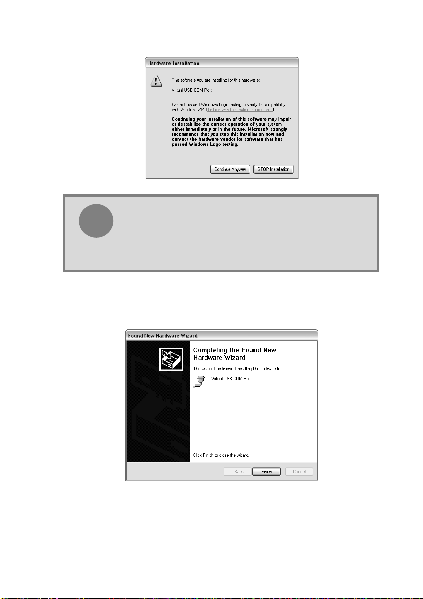
Hardware Setup
Note: this warning is related to the fact that the USB driver used by
the Evaluation Board is not digitally signed by Microsoft, and
i
Click the “Continue Anyway” button.
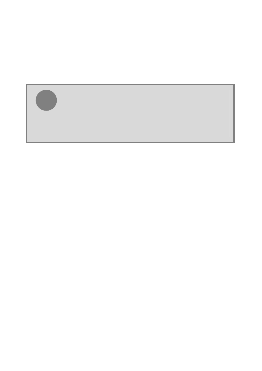
14. Windows will install the driver files to your system. At the end of the installation, the
following dialog box will appear.
Windows considers it to be potentially malfunctioning or dangerous
for the system. However, you can safely ignore the warning, since
every kind of compatibility/security test has been carried out by
SofTec Microsystems.
Click the “Finish” button to exit from the “Found New Hardware Wizard” procedure.
15. The Evaluation Board’s USB virtual COM driver is now installed on your system.
Page 16
Page 19

EVBQE128 User's Manual
5 Operating Modes
5.1 Overview
The Evaluation Board can work in two modes: “standalone” mode and “host” mode.
5.2 Standalone Mode
In standalone mode, no PC connection is required. Both microcontrollers are factory
programmed with the same sample application.
To run the built-in example:
1. Power off the board.
2. Put either the MC9S08QE128 or MCF51QE128 microcontroller in the socket.
3. Ensure that all of the jumpers in the “I/O” sections are inserted.
4. Power on the board.
5. Press the "PTD4" push-button. The value of the ADP0/PTA0 potentiometer will be
displayed on the PTE[7..0] LEDs.
6. Press the "PTD5" push-button. The value of the light sensor will be displayed on the
PTE[7..0] LEDs.
7. Press the "PTD6" push-button. The ADP0/PTA0 potentiometer will vary the frequency of
the sound played by the buzzer.
8. Press the "PTD7" push-button. The value of the temperature sensor will be displayed on
the PTE[7..0] LEDs.
The output of the potentiometer, light sensor and temperature sensor is also sent to the host
PC (if connected) through the virtual COM port over the USB connection. To see the data sent
to the virtual COM port, do the following:
1. Ensure that the J206 jumpers (“COM1 ENA”) select the “MDI” position;
2. Connect the board to the PC through the USB connection;
3. Start your terminal utility (e.g. HyperTerminal) with these parameters:
Baud rate: 9600
Data bits: 8
Parity: None
Stop bits: 1
Flow control: None
Page 17
Page 20
Operating Modes
5.3 Host Mode
In host mode the program execution is controlled by the host PC through the “USB” connector.
You can use the PC to debug the application by, for example, executing the program step by
step and watching how the microcontroller registers vary, using the provided CodeWarrior
Development Studio.
Note: the MC9S08QE128 and MCF51QE128 devices contain a singlewire background debug interface which supports in-circuit programming of
i
To work in host mode (using the built-in microDART interface):
Make sure that the board is powered on;
Make sure that the “RESET” and “BKGD” jumpers in the “microDART INTERFACE”
section are inserted;
Connect the host PC to the board through the provided USB cable.
on-chip non-volatile memory. This system does not interfere with normal
application resources. It does not use any user memory or locations in the
memory map. The Background Debug Module (also known as
Background Debug Controller, BDC) uses a single-wire communication
interface (via the BKGD line) to allow non-intrusive access to target
system memory and registers.
Page 18
Page 21

EVBQE128 User's Manual
6 Application Tutorial
6.1 Overview
MC9S08QE128 and MCF51QE128 devices share the same peripherals and registers.
Software written for one device can be easily recompiled for the other.
This section will provide a step-by-step guide on how to launch a MC9S08QE128-based
project and get started with the CodeWarrior user interface. Later, the same project will be
converted for the MCF51QE128 device.
6.2 MC9S08QE128 Step-by-Step Tutorial
The sample application is the same as the one described in the “Standalone Mode” section
above.
1. Make sure that the MC9S08QE128 device is present in the socket.
2. Set up the board so that it works in host mode (see “Host Mode” above).
3. Ensure that the Evaluation Board is connected to the PC (via the USB cable) and that
the board is powered on.
4. Start CodeWarrior by selecting it in the Windows Start menu.
5. From the CodeWarrior main menu, choose “File > Open” and choose the “\Program
Files\Freescale\[CodeWarrior Folder]\(CodeWarrior Examples)\HCS08\Evaluation
Board Examples\EVBQE128\C\Demo\Demo.mcp”.
6. Click “Open”. The Project window will open.
7. The code of this example is contained in the “main.c” file. Double click on it to open.
8. From the main menu, choose “Project > Debug”. This will compile the source code,
generate an executable file and download it to the evaluation board.
9. A new debugger environment will open. From the main menu, choose “Run >
Start/Continue”. The program will be executed in real-time.
10. From the main menu, choose “Run > Halt”. The program execution will stop. The next
instruction to be executed is highlighted in the Source window.
11. From the main menu, choose “Run > Single Step”. The instruction highlighted in the
Source window will be executed, and the program execution will be stopped immediately
after.
12. From the main menu, choose “Run > Start/Continue”. The application will restart from
where it was previously stopped.
Congratulations! You have successfully completed this tutorial! You can continue to
experiment with the CodeWarrior user interface and discover by yourself its potentialities. For
Page 19
Page 22
Application Tutorial
an in-depth guide of all of the user interface features, select “Help > CodeWarrior Help” from
CodeWarrior Development Studio’s main menu.
6.3 Converting the Example for the MCF51QE128
The same example illustrated above can be easily converted to work with the MCF51QE128
device.
1. Open the project you want to convert. In this case, from the CodeWarrior main menu,
choose “File > Open” and choose the “\Program Files\Freescale\[CodeWarrior
Folder]\(CodeWarrior Examples)\HCS08\Evaluation Board
Examples\EVBQE128\C\Demo\Demo.mcp”.
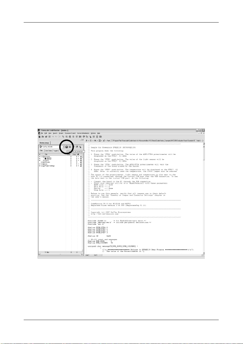
2. In the project pane, click the “Change MCU/Connection” button (see below).
The following dialog box will appear.
Page 20
Page 23
EVBQE128 User's Manual
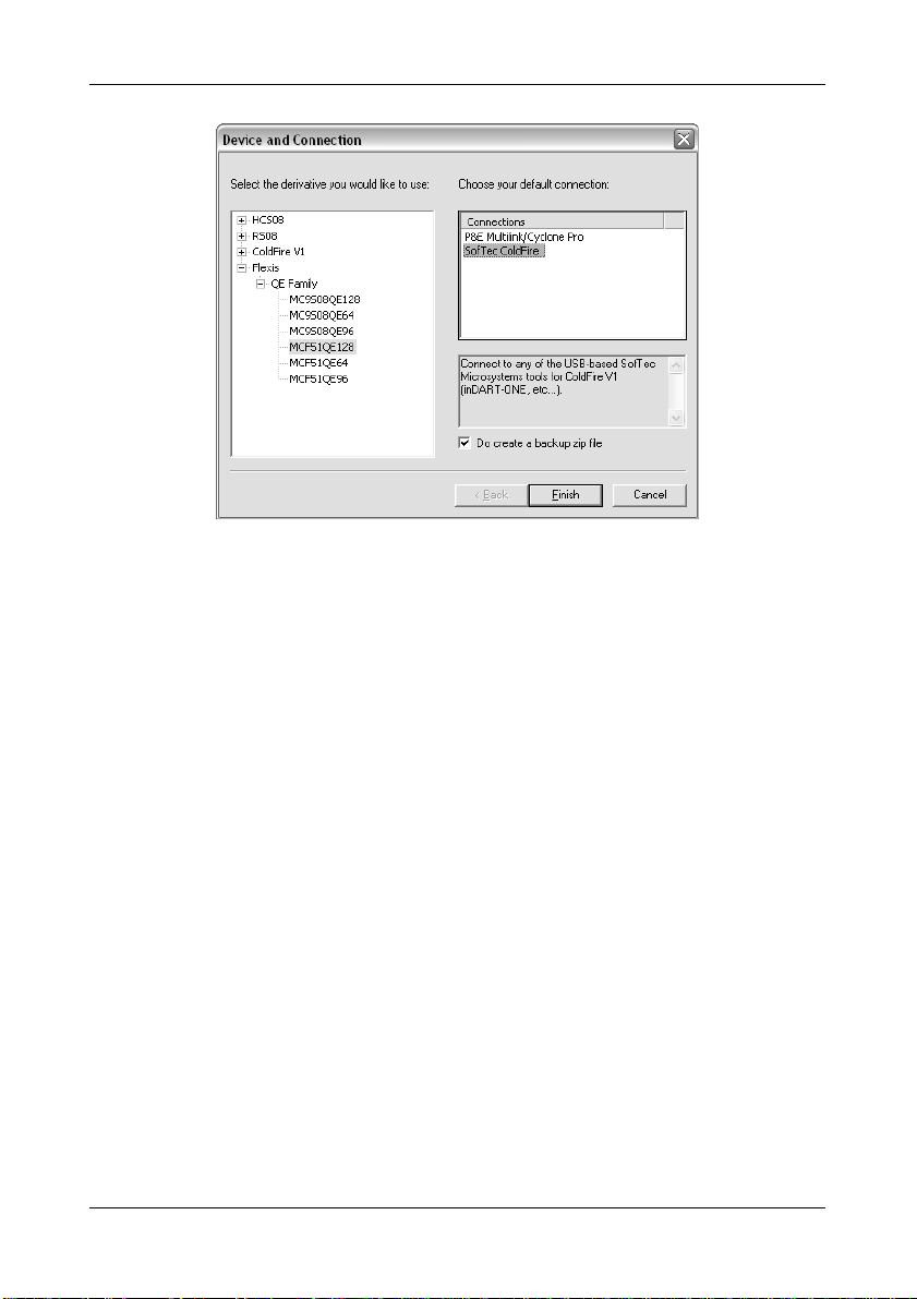
3. In the tree on the left, choose the MCF51QE128 device and, on the connections list,
choose “SofTec ColdFire”. Click the “Finish” button. Project conversion is done and
the new project is ready to be compiled.
A similar procedure may be used to convert a MCF51QE128 project into a MC9S08QE128
project.
6.4 Additional Examples
Two additional examples are provided:
DemoLCD. Shows how to drive the optional 16x2 LCD controller. A string is shifted from
right to left on the first LCD row. Any LCD based on the HD44780U (LCD-II) controller is
correctly driven. Make sure to comment/uncomment the appropriate delay line in the
delay.c file depending on which device you are working with.
MicroDartDemo. Shows how to communicate with the target microcontroller through
the microDART interface.
Page 21
Page 24

Page 25
EVBQE128 User's Manual
7 Hot Plug-In
7.1 Overview
The “Hot Plug-In” feature gives you the possibility to connect to a target microcontroller that is
running an application and to trace and debug the current running code without the need of a
complete erase and re-program of the flash memory.
7.2 How to Enable Hot Plug-In
While the target application is running:
1. Launch CodeWarrior.
2. Open the target application project.
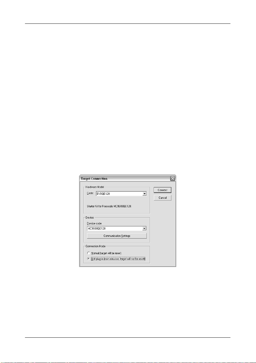
3. Start a debugging session (“Project > Debug”). The following dialog box will appear.
Make sure that the “Hot plug-in” connection mode is selected, then click the
“Connect” button.
4. The following dialog box will appear.
Page 23
Page 26

Hot Plug-In
Click “Cancel”.
5. The following dialog box will appear.
Click “Yes”. You will enter the debugging environment.
6. After issuing an halt command (“Run > Halt”), the Program Counter and all of the other
registers are updated with the actual microcontroller values.
Page 24
Page 27

EVBQE128 User's Manual
8 Jumper and Connector Settings
8.1 Jumpers
Name Reference Description/Pinout
J103
J202
J204
J205
J206
2
1
3
4
6 5
8 7
10 9
12 11
PTB6/PTB7 MODE SELECTION
1-3, 2-4 (“ALT. FUNCTION”): PTB6 and PTB7 lines are used
either as I
2
C lines (must be
enabled via software) or as
5-7, 6-8 (“CRYSTAL”): PTB6 and PTB7 lines are
user I/Os (default)
connected to the Y101 crystal
oscillator
9-11, 10-12 (“EXT OSC”): PTB6 and PTB7 lines are
connected to the U102 external
1
2
3
2
1
4
3
6 5
8 7
POWER SELECTION
1-2 (“USB”): Power supply is taken from the USB bus
2-3 (“12V”): Power supply is taken from the barrel
connector (default)
LCD ENABLE
Installed: Connects the SPI2 function of the
microcontroller to the LCD driving
circuitry (default)
oscillator (“EXT OSC1”)
Not Installed: The SPI2 function of the microcontroller is
1
2
3
2
1
4
3
6 5
COM ENABLE
1-2 (“ON=1”): Enables the RS-232 transceiver (ANDed
2-3 (“OFF”): RS-232 transceiver disabled
MDI/COM1 SELECTION
1-3, 2-4 (“MDI”): TXD1 and RXD1 signals of the
not connected to the LCD driving circuitry
with PTG0) (default)
microcontroller are routed to the
microDART interface (default)
3-5, 4-6 (“COM1”): TXD1 and RXD1 signals of the
microcontroller are routed to the RS-232
transceiver
Page 25
Page 28

Jumper and Connector Settings
Name Reference Description/Pinout
J207
2
1
4
3
COM2 ENABLE
Installed: TXD2 and RXD2 signals of the
Not Installed: TXD2 and RXD2 signals of the
J301
1
LED ENABLE
Installed: The “PTEx” LEDs are connected to the
Not Installed: The “PTEx” LEDs are not connected to the
USER1 ENABLE
J302
1
Installed: Connects the indicated microcontroller
Not Installed: The indicated microcontroller signal is not
J303
1
3
2
4
IIC1 PULL-UP ENABLE
Installed: Enables 10KOhm pull-up resistors on
Not Installed: Disables 10KOhm pull-up resistors on
J304
2
1
4
3
IIC2 PULL-UP ENABLE
Installed: Enables 10KOhm pull-up resistors on
Not Installed: Disables 10KOhm pull-up resistors on
J305
1
USER2 ENABLE
Installed: Connects the indicated microcontroller
Not Installed: The indicated microcontroller signal is not
microcontroller are routed to the RS-232
transceiver (default)
microcontroller are not routed to the RS232 transceiver
PTE[7..0] ports of the microcontroller
(default)
microcontroller
signals to the relative I/O device (default)
connected to any I/O device
SDA1 and SCL1 signals of the
microcontroller (default)
SDA1 and SCL1 signals of the
microcontroller
SDA2 and SCL2 signals of the
microcontroller (default)
SDA2 and SCL2 signals of the
microcontroller
signal to the relative push-button
(default)
connected to a push-button
Page 26
Page 29

EVBQE128 User's Manual
Name Reference Description/Pinout
J402
2
1
4
3
USB TO BDM ENABLE
All installed: The microDART interface is enabled
Not Installed: The microDART interface is disabled
(default)
Page 27
Page 30

Jumper and Connector Settings
8.2 Connectors
Name Reference Description/Pinout
J101
J102
12
3
4
5
6
78
77 78
79 80
12
3
4
5
6
MCU pin replication
BDM Connector
1. BKGD
2. GND
3. N.C.
4. RESET
5. N.C.
6. 3V
12 V DC Power Supply Input Connector (Barrel, 2.1 mm)
1. 12 V DC
2. GND
MCU POWER Connector
1. MCU_VDD
2. MCU_VSS
J201
J203
2
1
1
2
3
4
3. MCU_VDDA
4. MCU_VSSA
LCD Connector
1. GND
2. 5V
3. CONTRAST
4. RS
5. GND
J208
12
3
4
5
6
78
910
11 12
13 14
6. EN
7. GND
8. GND
9. GND
10. GND
11. DB4
12. DB5
13. DB6
14. DB7
Page 28
Page 31

Name Reference Description/Pinout
J209
RS-232_1 Connector
1. Connected to pins 4, 6
5 1
69
2. TX
3. RX
4. Connected to pins 1, 6
5. GND
6. Connected to pins 1, 4
7. N.C.
8. N.C.
9. N.C.
J210
RS-232_2 Connector
1. Connected to pins 4, 6
5 1
69
2. TX
3. RX
4. Connected to pins 1, 6
5. GND
6. Connected to pins 1, 4
7. N.C.
8. N.C.
9. N.C.
J401
USB Connector
1. 5 V DC USB Bus Power Supply Line
2. USB D-
3. USB D+
4. GND
EVBQE128 User's Manual
Page 29
Page 32

Page 33

EVBQE128 User's Manual
9 Troubleshooting
9.1 USB Driver Problems
If you connected the Evaluation Board to the PC before installing CodeWarrior, the Evaluation
Board’s USB drivers may not have been correctly installed on your system. Unplugging and
replugging the USB cable is of no use, since Windows has marked the devices as “disabled”.
As a consequence, the PC cannot communicate with the Evaluation Board.
To restore/upgrade the USB drivers (provided CodeWarrior has been installed), perform the
following steps under Windows XP:
1. Connect the Evaluation Board to the PC.
2. Open the Control Panel (Start > Settings > Control Panel).
3. Open the “System” options.
4. Select the “Hardware” tab.
5. Click the “Device Manager” button.
6. Two “EVBQE128” devices will be shown with an exclamation mark next to it.
7. For each device, double click on it and, in the “General” tab, click the “Reinstall
Driver” button. Follow the on-screen instructions.
9.2 Communication Problems between the PC and the
Demo Board
1. Make sure that the “BKGD” and “RESET” jumpers in the “USB” section are inserted.
2. Make sure that the microcontroller is powered:
Make sure that the “ON-OFF” switch in the “POWER SUPPLY” section selects the
“ON” position;
Make sure that the “POWER SEL” jumper in the “POWER” section selects the
appropriate power supply source.
9.3 Problems with RS-232 Communication
The Jumper J205 allows the user to control the state of the RS-232 transceiver: when the
position 1-2 (“ON”, default position) is selected, the RS-232 transceiver is enabled (with the
aid of an external pull-up), but the user has the option to turn the transceiver off (on) by driving
the PTG0 line of the microcontroller low (high).
When the position 2-3 (“OFF”) is selected, the RS-232 transceiver is powered off via
Page 31
Page 34

EVBQE128 User's Manual
hardware, without the need of any microcontroller action, in order to minimize the power
consumption of the board.
In order to communicate via the RS-232_2 COM port, you must remove the “ACMP2-ENA”
and “ADP0/ACMP1+ ENA” jumpers. These pins are shared with other I/O functions that can
generate hardware conflicts with the RS-232 communication.
Page 32
Page 35

Page 36

SofTec Microsystems™ and the SofTec Microsystems logo are trademarks of SofTec Microsystems S.p.A. Freescale™ and the Freescale logo are trademarks of Freescale
Semiconductor, Inc. All other product or service names are the property of their respective owners.
 Loading...