

Page 1
User's Manual
Safe,Simple and Efficient
www.freeroadgps.com
www.freeroadgps.com
i-288
Diim po rt /Diedar :B EY OND TRADI NG S DN .BHD.
Address:No .37-39-41- 43,Jalan Kas uarina 5/KS 7, Bandar Botan ic,41200 Klang ,
Selangor Dar ul Ehsan, West Ma laysia.
Tel:+603-3325 2255( hunting line ) Fax:+603-332 5 1155
Email:betr ading2003@ yahoo.com Web site:www.beyon d.com.my
by Debezt
Smart Tracking SystemGPS
M3
One-Key Smart Monitor & ControlOne-Key Smart Monitor & Control
Smart Tracking SystemGPS
Page 2
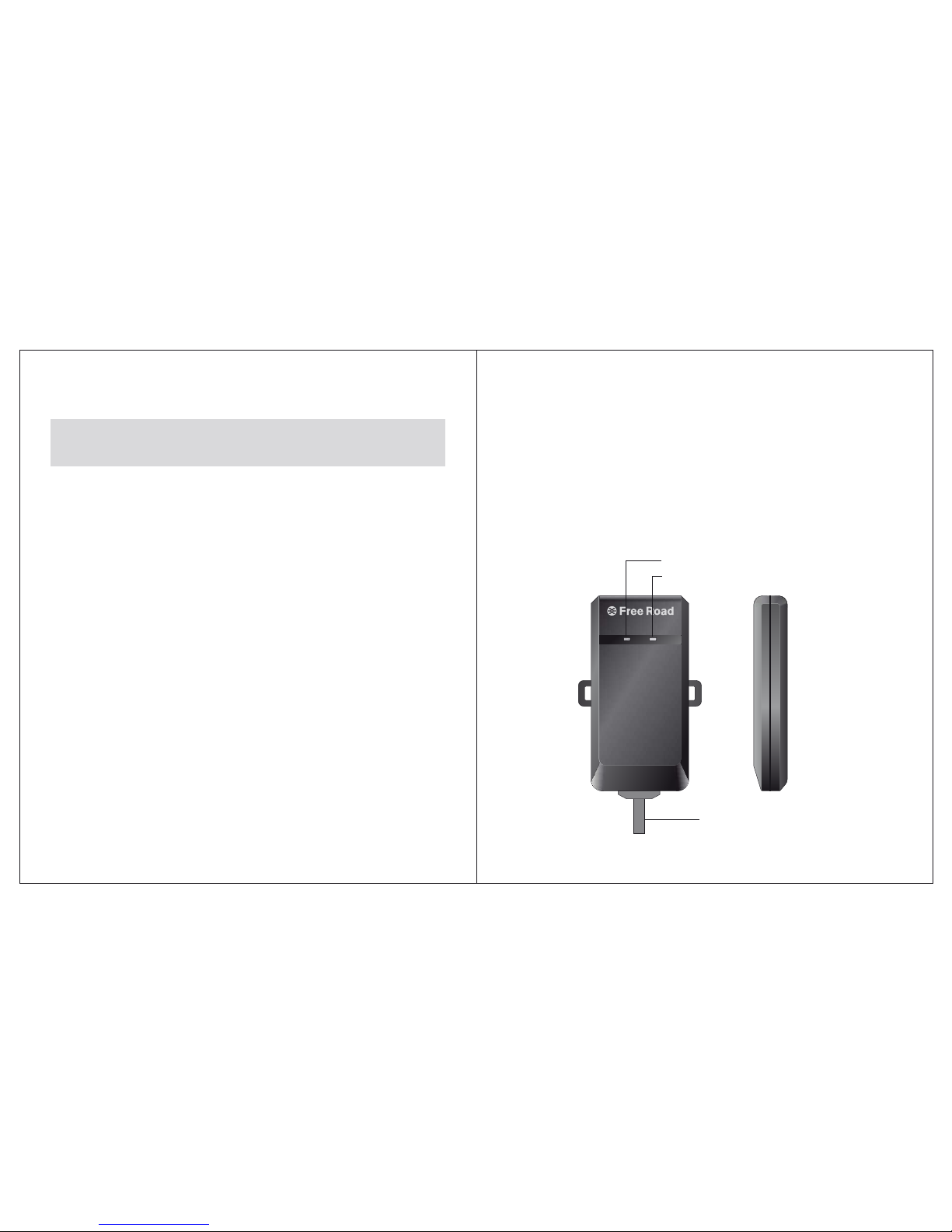
Table of contents
1. Product's features
GPS Tracking System is a multi-function tracking device, having
functions such as positioning and Anti-theft.
Please read carefully this operating manual for maximising the usage
of the product. Please keep this manual in safe custody for future use.
2. Product's overview
- 1 -
GPS Tracking System
1. Product's features.................................................................................1
2. Product's overview................................................................................1
3. Product components..............................................................................2
4.Operation................................................................................................2
5. Device's socket connection diagram .....................................................7
6. Using the web base enquiry portal for positioning and enquiry.............8
7. Guideline on the services fee for the device's SIM card.....................16
8. Matters for attention.............................................................................16
9. Technical data......................................................................................16
GSM GPS
GPS
Trac king Sy stem
i-2 88
by Debezt
M3
System wiring connection socket
GPS status indicator
GSM signal indicator
Page 3
4.1 Installing the SIM card
The SIM card must be able to send and receive SMS text message, with caller
display function enabled and be able connecting to GPRS.
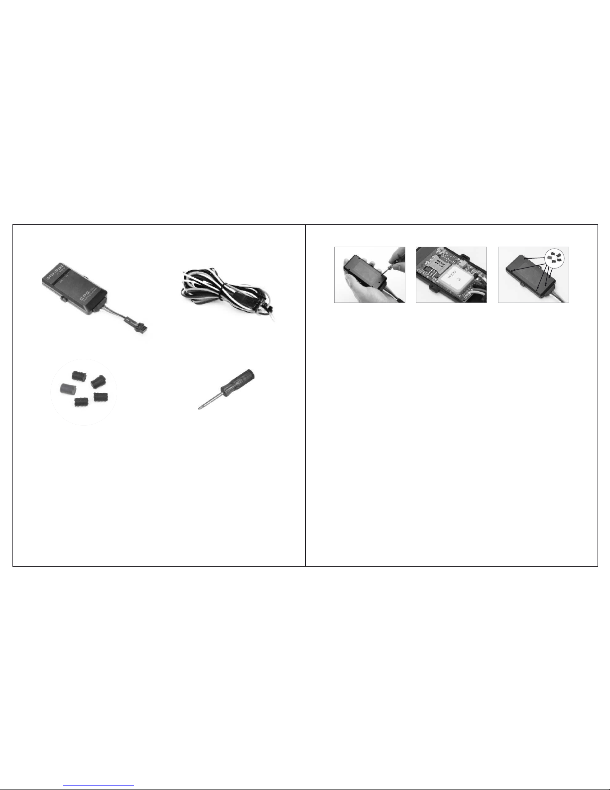
A. Loosen back cover of the device with the screw driver,the SIM card slot can be
found in the PCB board.
B. Insert the SIM card inside the SIM card slot and lock it up(note the direction of SIM
card),then tighten the screw to the back cover.
C. Plug the 4 screw holes with the supported sealing plug(if the equipment is installed
out of the vehicle,it must be sealed with a screw plug screw holes will be plugged,
or the device won't have the waterproof funciton).
- 3 -
- 3 -
- 2 -
4.2 Status of Indicators
A. GSM Indicator (Blue): Indicator for telecommunication signal. Once connected to
the GSM network, the indicator should flash twice in every 3 seconds.
B. GPS Indicator (Green): The flashing green light indicates that GPS is receiving
satellite signals. Light will stay green when satellite signals is settled
4.3 Setting the monitoring mobile phone
The monitoring mobile phone will be used to set up and modify the system
setting. The monitoring mobile phone will receive SMS text message warning alert
being sent from the GPS device. Before setting up the system’s monitoring functions,
the user must register one monitoring mobile phone numbers .Write a SMS text
message to the device’s SIM card phone number through the phone number.
The device’s SIM card phone number is the recipient of the following
SMS text message.
Setting the monitoring mobile phone number: It is suggested that the primary
mobile phone number be the usual driver of the vehicle.
SMS text Format: 100, mobile phone number
Example: 100,0163322888
Returned SMS text message: Monitoring mobile phone settings success
Remark: The input mode must be in English for entering the full content
of the SMS text message, otherwise, the set up will not be successful.
The same apply to all the other system settings.
4.4 Actively quer y
It is convenient for the owner to wake up the query and positioning the monitored
vehicle at any time.Send the SIM card’s phone number through the monitoring mobile
phone number a SMS text message to enquiry the device’s status.
Send the SMS text message: 700
Returned SMS text messages: The current latitude, longitude, speed, direction,
3.Product components
Socket connection wires
4.Operation
Main unit of the GPS
Positioning device
Screw Driver
Sealing plug
Page 4

- 4 - - 5 -
temperature, voltage.(If the device can not be located, the return message:
Unpositioning, temperature, voltage)
Send the SMS text message: 600
Returned SMS text messages:The current specific address.(If the device can not be
located, the return message: Unpositioning, temperature, voltage)
Remark:The enquiry must be made through the monitoring mobile
phone number. The other registered mobile phone numbers have no
right to make such enquiry.
4.5 Activate/Deactivate the Anti-T heft function
Activation/Deactivation by sending SMS text message.
Activation: Send to the SIM card phone number through the primary mobile phone
number a SMS text message.
Sent the SMS text message: 111
Returned SMS text message: System activated
Deactivation: Send to the SIM card phone number through the primary mobile
phone number a SMS text message.
Sent the SMS text message: 112
Returned SMS text message: System deactivated
4.6 Anti-theft warning alert by SMS/GPRS
The device will release alert message for the events of unlawful ACC ignition
start and abnormal vehicle movement. If any one of these events is detected, the
device will release warning alert to themonitoring mobile phone number a SMS text
message and GPRS signal to the web base enquiry portal.
A. Alert for unlawful ACC ignition start
When the device is activated (the device is properly connected to the ACC ignition
device), in the case when unlawful ACC ignition start is detected, the device will
send to the primary mobile phone number two SMS text messages: Alert!
Abnormal start detected.the latitude and longitude. The device will also send
the same message to the web base enquiry portal by GPRS signal.If device is not
positioned then you will receive a text message: Alert! Abnormal start
detected,unpositioning.
B. Abnormal vehicle movement
When system is in anti-theft mode, if there is a 10m/s of movement detected on
the monitored vehicle, car owner will receive a warning text message: Anti-theft
alarm, vehicle has been detected abnormal movement! Longitude, latitude.
meanwhile, system will report the abnormal movement of the vehicle to the
monitoring platform.
4.7 Region-fencing warning
The setting for region-fencing must be done through marking the pre-determined
region at the online map integrated with the web base enquiry portal. Once the region
is determined and the vehicle is driving in/out of the pre-determined region, the
device will send to the monitoring telephone number a SMS text message:Vehicle
moved in/out the monitoring region. the latitude , longitude . The device will also
send the send message to the web base enquiry portal by GPRS signal.
Remark: The region-fencing can only be determined or cancelled
through the web base enquiry portal. Region-fencing will remain
function until it is being deactivated. (Please deactivate the function if
region-fencing is not required, this will help save the SIM card’s SMS
text message cost).
4.8 Speeding aler t
The speeding limit can be determined through the web base enquiry portal. When
the vehicle is travelling above the pre-determined speed limit, the device will send to
the monitoring mobile phone number a SMS text message: Vehicles Speeding! the
latitude, longitude . The device will also send the same message to the web base
enquiry portal by GPRS signal.
Remark: The speeding alert can only be activated/deactivated through
the web base enquiry portal. Speeding alert will remain function until it
is being deactivated. (Please deactivate the function if speed alert is not
required, this will help save the SIM card’s SMS text message cost.)
4.9 Email Alarm Function
After the users setting the email alarm fu nction on monitoring pla tform throught
computer,all the alarm message from the device will sent to the appoint ment email
address(Please reference the operation manual page14,email alarm setting)
4.10 Function of Remote Flameout
When a vehicle is abnormal and gives an alarm, the user can s tart the func tion of
remote flameout for the vehicle by monit oring platf orm, and the ve hicle will
automatically shut down engine.
Page 5
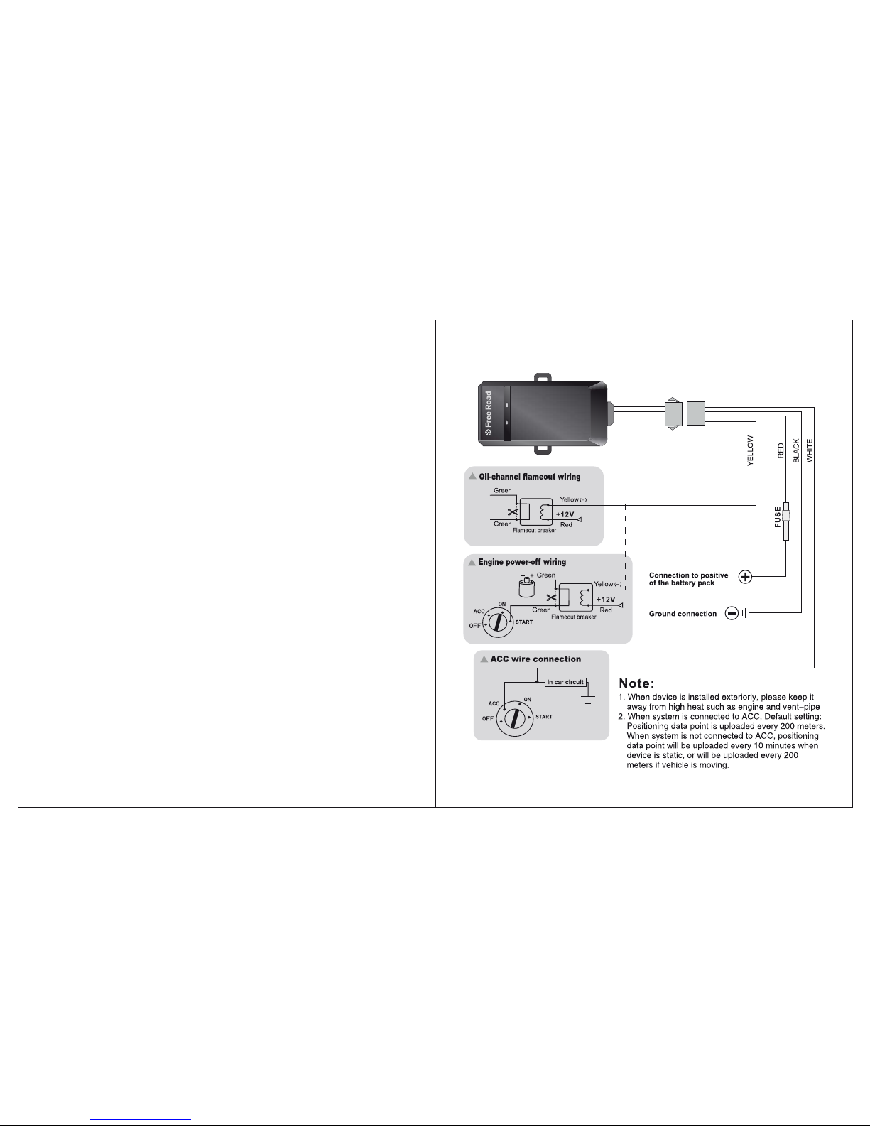
5. Device’s socket connection diagram
Flameout Settings: In the operation menu of platform, click “Engine Flameout” to pop
up the settings interface. After entering password and co nfirming, click the Enable key to
start the remote flameout for the vehicles. After that, the vehicle will automatically shut
down engine (After setting successfully, the platform will display the informati on of
Remote Flameout Has Been Set for Vehicle).At the same ti me, system will send an alert
text message to car owner's monitor phone number:En gine cut off started. the cu rrent
latitude, l ongitude, s peed, direction.
Cancel Flam eout: In the operation menu of platform, c lick “Cance l Engine Flameout” to
pop up the settings interface,input the password of device and confirm this operation.At
the same time, system will send an alert text message to car owner's monitor phone
number:En gine cut off disable. the current latitude, longitude, speed, direction.
Remark:
1. Vehicles must be connected to the ACC wire group can be achieved
remotely turn off features.
2. After user activate flameout function,vehicles will start up flameout in 1
minute, it make the oil-circuit flameout or power control flameout for a
moving vehicle, it will likely lead to vehicles can not normal safe driving,
to ensure the safety of vehicles traveling, we strongly recommend that
users turn off their engines after parking the vehicle
Special Note:
If there is any security problems and accidents because of using the
FLAMEOUT function, it has nothing to do with the company.
4.11 Data Uploading
GPS device Device will upload data at specified times (Every 200 meters as default
setting).user can modify the distance or time interval of data uploaded on the pl atform
action bar of the "tracking".
- 6 -
- 7 -
GSM GPS
GPS
Track ing Sys tem
i-288
by Debezt
M3
Page 6
- 8 - - 9 -
This column shows
vehicle's license plate
number, group, time of
record uploaded, Longitude,
latitude, Speed, Direction,
Address, status, Signal of
GPS and GSM, Battery
Volume.
Details
Vehicle num ber:JEREMY
Group:D efault
Time:200 9-12-15 18:2 3:21
Latitud e:-27.6364 60
Longitu de:152.823 728
Speed:5 5.2(km/h)
Heading :70.2(to eas t)
Address :LOT 17 Redbank P lains Rd,
Redbank P lains QLD 4301 , Australia
Status: Protect ACC
Power:1 00.0%
Details
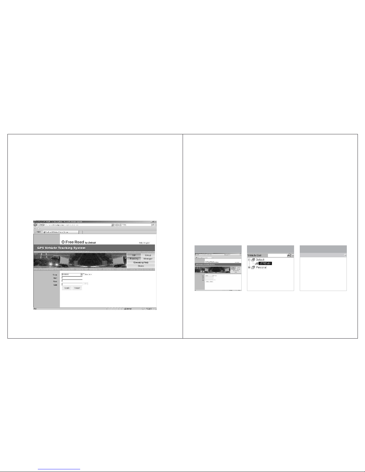
When login to the website,
www.freeroadgps.com,please
fill in group ID, user ID,
password & security code
correctly for successful login.
Select the vehicle that you
like to make the enquiry from
the list of registered vehicles.
Vehicles List
First page of the web site
6.2 Operating the function interface
User can use different functions at the service platform for operation or
inquiry about information. If the user is unfamiliar with operation, he or she may
consult the operation illustration at the control platform.
GPS vehicle monitoring and management portal is a free open platform.
User can use it free of charge. The weather condition and external environmental
factors could have impact on the actual location of the vehicle against the coordinate as shown on the monitoring map, or the driving track against the actual
road map. It is also possible that the portal has not received accurate map data at
any given time. User could also find discrepancy on the actual location of
buildings, road condition and other relevance information against the data that
you may obtain from the map. User will solely held responsible for liability of
any kind caused by the use of data or information obtained from using the map
provided by Google. Google will not be liable for any claim or damages, whether
directly or indirectly, caused by the inaccurate data/information.
6.3 Operation illustration at the control platform
6.Using the web base enquiry portal for
positioning and enquiry
6.1 Logging into the server
Logging into the web site, , the interface for signing
into the GPS vehicle enquiry management device will pop up, fill in group
name, user name, sign-in password and the security code. Once properly done,
the interface for positioning enquiry and monitoring will then be signed in.
Remark: Individual user should select “VIP” user. If the portal is not
in use for more than one hour, the device will log-off automatically.
User must log-in again for accessing the portal.
www.freeroadgps.com
Page 7
-10 - - 11 -
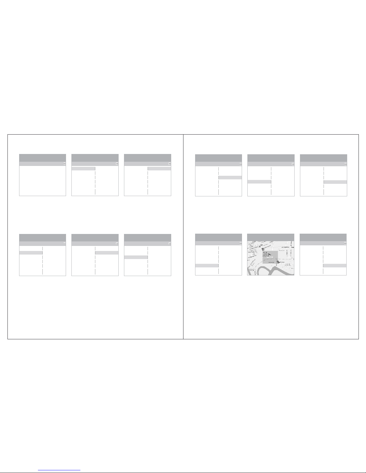
Setting up the speed limit
in which the vehicle can travel.
The system will send warning
alert SMS text message to the
user if it has been travelled
above the speed limit.
Continuous positioning
function will be terminated.
Speed Limit Cancel Limit
Cancelling the setting for
speed limitation and the
system will stop sending
alert message to the user.
Cancel Track
Operat ion
Auto Center
Show Trace
Tracking
Speed Limit
Region Defend
Normal Show
Hide Trace
Cancel Track
Cancel Limit
Cancel Defend
Engine
Flameout
Cancel Engine
Flameout
Operat ion
Auto Center
Show Trace
Tracking
Speed Limit
Region Defend
Normal Show
Hide Trace
Cancel Track
Cancel Limit
Cancel Defend
Engine
Flameout
Cancel Engine
Flameout
Operat ion
Auto Center
Show Trace
Tracking
Speed Limit
Region Defend
Normal Show
Hide Trace
Cancel Track
Cancel Limit
Cancel Defend
Engine
Flameout
Cancel Engine
Flameout
Under the region defend,
an area selection window will
pop out, click on the area
button above the map, and
point the cursor on two
positions and click out an
rectangular region, then
confirm the drawn region by
click on set tab to complete
the geo-fencing process.
Once the function for
region-fencing is activated,
the system will send alert
message whenever the
vehicle is driving in or out of
the determined region/area.
Cancel Defend
Deactivating all the
settings that have been done
previously.
Region Defend Region Defend
Operat ion
Auto Center
Show Trace
Tracking
Speed Limit
Region Defend
Normal Show
Hide Trace
Cancel Track
Cancel Limit
Cancel Defend
Engine
Flameout
Cancel Engine
Flameout
Operat ion
Auto Center
Show Trace
Tracking
Speed Limit
Region Defend
Normal Show
Hide Trace
Cancel Track
Cancel Limit
Cancel Defend
Engine
Flameout
Cancel Engine
Flameout
Information/status of the
selected vehicle will then be
locked up and displayed at
the map.
This box displays the
setup status of continuous
positions, speed limits and
zone arming.
Set Stat us
Tracking:Nothin g
Speed Limit:No thing
Region Defend: Nothing
Set Status Auto Center Normal show
Once the vehicle lock up
is released, the system will
then be returned to the
normal mode.
The real time tracking in
which the vehicle is being
travelled will be hided.
Displaying the real time
tracking in which the vehicle
is being travelled.
Hide Trace Tracking
The positioned equipment
is subject to continuous
positioning according the
distance or interval set for the
equipment.
Show Trace
Operat ion
Auto Center
Show Trace
Tracking
Speed Limit
Region Defend
Normal Show
Hide Trace
Cancel Track
Cancel Limit
Cancel Defend
Engine
Flameout
Cancel Engine
Flameout
Operat ion
Auto Center
Show Trace
Tracking
Speed Limit
Region Defend
Normal Show
Hide Trace
Cancel Track
Cancel Limit
Cancel Defend
Engine
Flameout
Cancel Engine
Flameout
Operat ion
Auto Center
Show Trace
Tracking
Speed Limit
Region Defend
Normal Show
Hide Trace
Cancel Track
Cancel Limit
Cancel Defend
Engine
Flameout
Cancel Engine
Flameout
Operat ion
Auto Center
Show Trace
Tracking
Speed Limit
Region Defend
Normal Show
Hide Trace
Cancel Track
Cancel Limit
Cancel Defend
Engine
Flameout
Cancel Engine
Flameout
Operat ion
Auto Center
Show Trace
Tracking
Speed Limit
Region Defend
Normal Show
Hide Trace
Cancel Track
Cancel Limit
Cancel Defend
Engine
Flameout
Cancel Engine
Flameout
Page 8
- 12 -
- 13 -
Click on “mana gement
system”, go to Vehicle
Management System, clic k
on “vehicle”, se lect
corresponding vehicl e's
license plate number to go
to manageme nt interfac e
and change ve hicle's
information.
Cancel Engine Flameout
Engine Flameout
Operat ion
Auto Center
Show Trace
Tracking
Speed Limit
Region Defend
Normal Show
Hide Trace
Cancel Track
Cancel Limit
Cancel Defend
Engine
Flameout
Cancel Engine
Flameout
Operat ion
Auto Center
Show Trace
Tracking
Speed Limit
Region Defend
Normal Show
Hide Trace
Cancel Track
Cancel Limit
Cancel Defend
Engine
Flameout
Cancel Engine
Flameout
History Trace
Histor y Trace
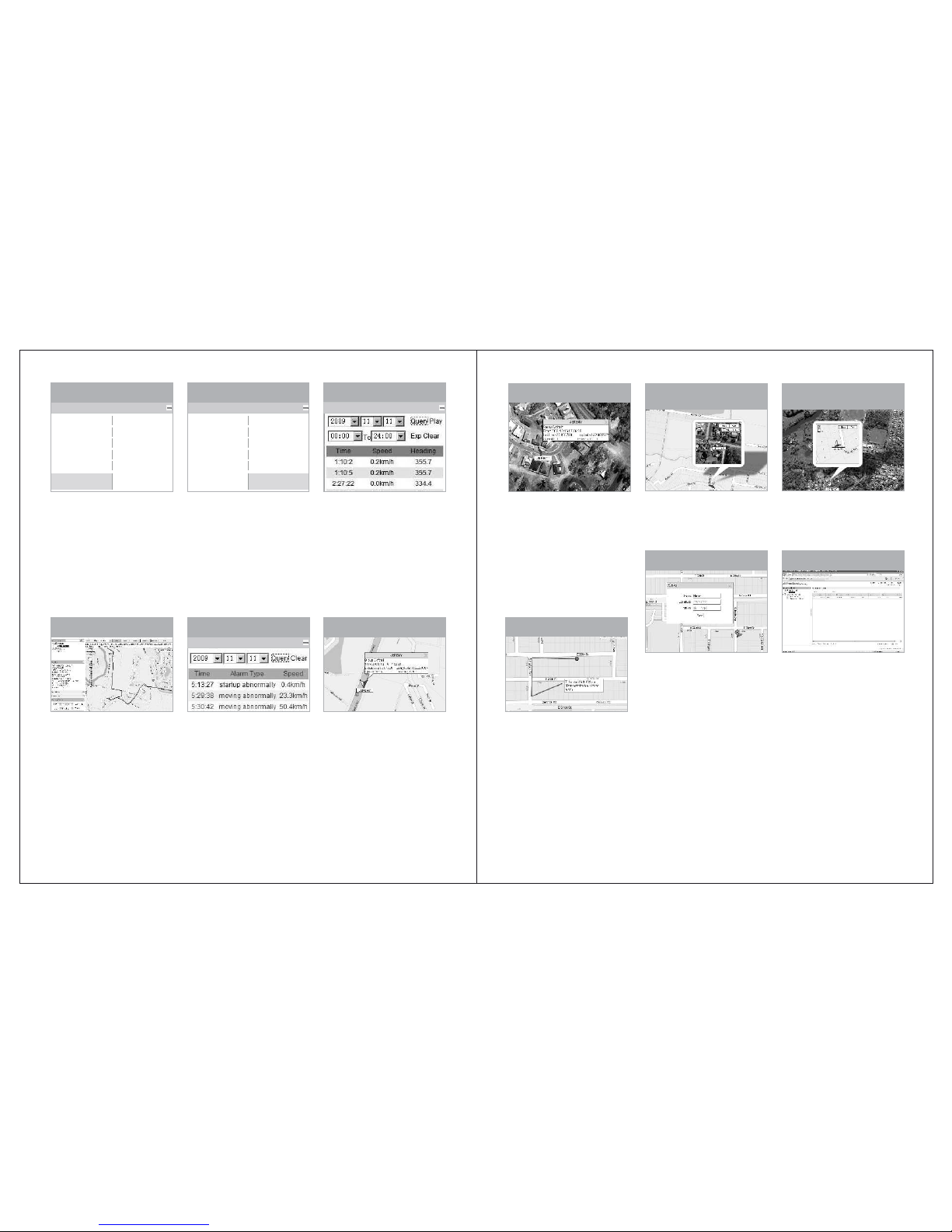
Click “Cancel Engine
Flameout” to pop up the
settings interface, input the
password of device and
confirm this operation.About 1
minute after apply the setting;
the “Engine Flameout”
signal will be cancelled.
Click “Engine Flameout” to
pop up the settings interface.
After entering password and
confirming, click the Enable key
to start the remote flameout for
the vehicles. About 1 minute
after apply the setting,
information bar will show
“Engine Flameout” to signal.
Alarm Qu ery
Alarm QueryHistory Trace
Select the date and time
required for inquiry.
Click “Inquire”,the historical
tracks of vehicles traveling at
this time section will be
displayed on the map, and
meanwhile, data about the
longitude and latitude at places
of vehicles in this time section
will be displayed on the list.
Click “Play” ,the historical
tracks of the vehicles inquired
about on the map will be
played back by frames.
Click “Export”, the detailed
historical track data about the
vehicles inquired about will be
opened or saved in the Excel
file format.
Click “Clear”, the data
inquired, played back and
exported as previously
selected will be all deactivated.
Select the year, month
and date required for inquiry
about, and then click on
Inquire, and the alarm data
on this vehicle given on a
designated date will be
displayed at the lower part of
the Inquire box.
Click "Clean” to be able
to close the alarm data list.
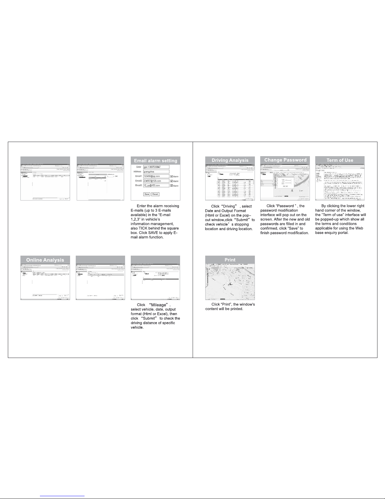
The blue icon in the
Google traffic map shows the
vehicle’s location. When
device has not uploaded
positioning data in 10
minutes, icon will turn grey.
When device uploads alarm
information, icon will turn red.
When replaying the historic
trace, icon will turn green.
Traffic Map
Satellite Map
The blue icon in the
Google satellite map shows
the vehicle’s location. When
device has not uploaded
positioning data in 10
minutes, icon will turn grey.
When device uploads alarm
information, icon will turn red.
When replaying the historic
trace, icon will turn green.
Under the traffic map, click
at the target place will show
the satellite map window for
comparison.
Under the satellite map,
click at the target place will
show the traffic map window
for comparison.
Real-time contrast of the traffic
maps and satellite maps
Real-time contrast of the traffic
maps and satellite maps
Measuring the Distance
The travelled dist ance
can be measured on the
Map.click "Measure" ,then
click the position that will
be measured on the map,
double-click to en d.
User can mark down
customized place on Google
map.
Click “Add POI”, window
for entering place of interest
will pop up, an icon will also
appear on the center of the
map.
Drag the icon to location
where you need to add the
name of interest on the map,
then enter words, click
“Save” to show the added
location.
Click the added location,
then press “Delete” on the
pop-out window, and confirm
to delete added location.
Management System
Add POI
Page 9
- 14 - - 15 -
Mileage
Click on“Unit ’s Status”,
Select corr esponding
license plate number to th e
latest uplo aded record , such
as Longitud e, Latitude ,
Speed, batt ery volume an d
others.
Unit's Status
Click on “
mileage”, select
corresponding license plate
number, enter the value of
mileage, then click on
“Submit” to set up initial
mileage.
Initialization
Click on “Enquire Total
Mileage”, select license
plate number to enquire
vehicle's initial mileage and
total mileage.
Total mileage
Click on “Report”,
go to Report window. Click
on “Online” , select Type
and Days, click on
“Query” to check out
online and offline devices.
Initialization mileage
Page 10

7. Guideline on the service fees for the device’s SIM
card
The SIM card inserted into the device is the mean of commun ication bet ween the
device and the user. There will be charges for "SMS text message" and "GPRS dat a
uploading", and the charges could be varied in accordance with the user's
preference and the setting for data uplo ading. The user will have to pay their own charges
to the respective telecom carriers.
8.Matters for atention
We are not liable for any cl aim against the Company if t he device is failed to receive
GPS signal due to the following circumstances:
A. Geographical reasons (e.g. the vehicle is locate d at a basin, rem ote mountain area, etc).
B. Surrounding environment (where the vehicle is surrounding with high rise buildings or
the vehicle is travelling inside a tunne l).
C. Building or construction, such as Power Station or Power Pole, which could interfering
the receipt of GPS signal.
D. Bad weather.
E. If medal heat insulating window film and heat-insulation course are applie d to the
vehicle's glass window, it will affect and reduce the GPS reception of signal, also GPS
may be unable to function properly. If GPS is unabl e to locate, please change the
installed position of GPS.
9.Technical data
Air interface: GSM/GPRS/GPS
Supported frequencies: GSM850/900/1800/1900 MHz, GPS 1575.42 MHz
GPS sensitivity: -147dbm ~ - 159dbm
Ambient temperature: -35℃ to 80℃
Working environmen t: Area with GSM/GPRS network coverage
Product size: 90 x45x14mm
Product weight: 50g
A. The SIM card must be able to send and receive SMS text messag e, with caller display
function enabled and be able connecting to GPRS.
B. In order to have the device functioned properly, please ensure that you have paid the
charges for the SIM card inser ted into the de vice on time.
- 16 -
 Loading...