

Page 1

1:8 Scale 4WD Electric Belt Driving
Buggy Manual
福瑞达模型有限公司
DONGGUAN FREERCHOBBY CO.,LTD
TEL/FAX :+86-769-82927540
www.freerchobby.com
Page 2

Contents
Preface……………………………………………………….....3
Safety Guidelines……………………………………………...3
Li-Po Battery Charging………………………………………..4
Operation Steps………………………………………………..5
Recommended Maintenance Tools……………………….....7
F8E-BX Exploded View…………………………………….....31
Spare Parts List……………………………………………......32
F8E-BX Installing view……………………………………….7-30
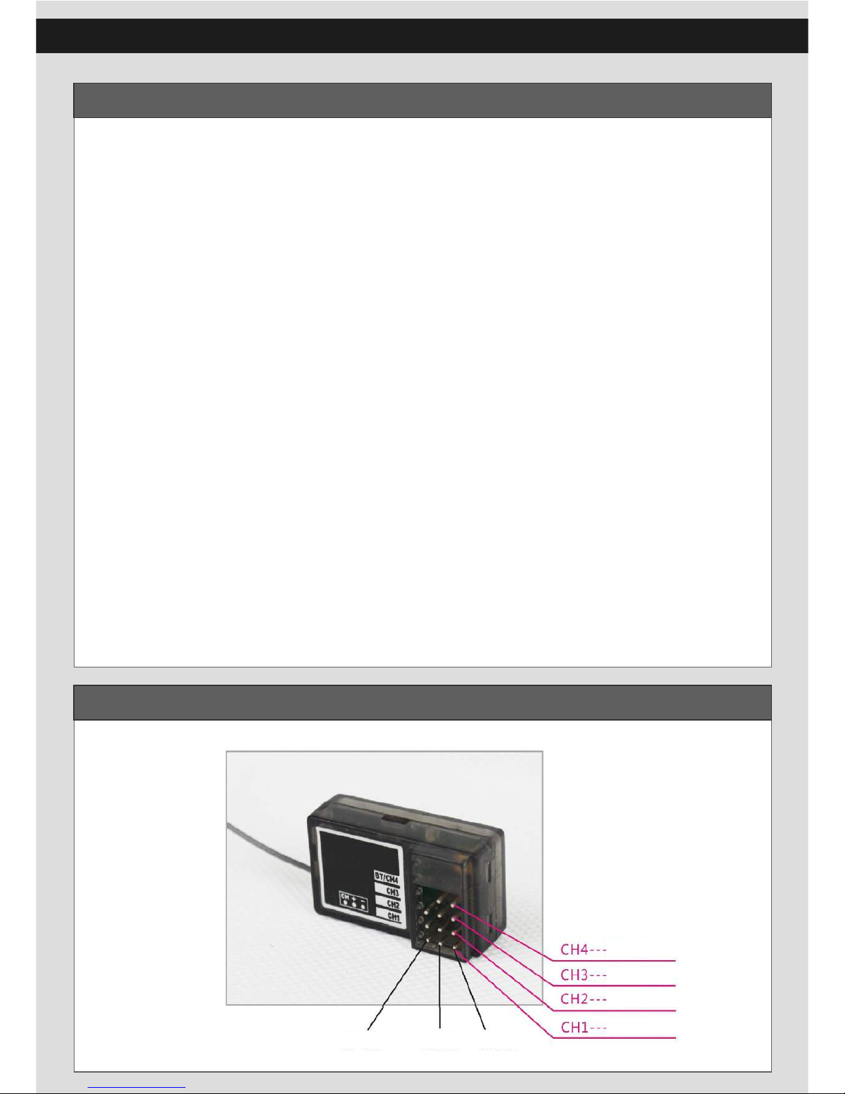
Receiver Connection……………………………………….....4
Page 3

3
Thanks for purchasing F8E-BX (1:8 scale 4WD Belt Driving
Buggy) from FREE RC HOBBY . This model was designed
by experienced design team from FRC hobby, and we tested
repeatedly and improved. Believe that FRC products will
bring more fun for you. Enjoy it!
Attention:
● Please read CD before operating to avoid any injuries for person or
property.
Preface
● Please pay more attention to the warnings and cautions in the manual.
Improper operation may cause personal and /or property damage. FRC
hobby has no control over damage resulting from shipping, improper
construction or improper usage.
● To prevent any serious injury and / or damage to property, please be
responsible when operating all remote controlled models.
Safety Guidelines
● This product is not suitable for children under 14 years of age
without the direct supervision of a responsible and knowledgeable
adult。
● Carefully read all of the warnings and cautions for any parts
used in the construction and use of your model.
● Keep small parts out of reach of small children. Children must
not be allowed to put any parts in their mouth.
● After using your model, please do NOT touch the equipment on
the model such as motor and ESC, because they generate high
temperatures. You may seriously burn yourself.
● This model car is not intended for use on public places and can
conflict with or disrupt pedestrian or vehicular traffic.
Page 4
4
Re-Linking the Transmitter and Receiver
Power Input
Channel 3
ESC
Steering Servo
Signal Wire
Power +
Power -
Li-Po Battery Charging
Charging Procedure
● Connecting the power supply, the light of the charger will indicate
red and green alternately.
● Connecting battery and charger,the light of the charger will indicate red.
● When the three lights indicate green,charging finished.
● Take off all of the connector.
Caution
● Please take out the battery from the car and take off the T-plugs before
charging.
● Please put the battery and charger at cooling place and far away from
the heat source and tinder when charging.
● Please use balance charger for charging.
● Please take care and not take the charger and battery out of your reach ,
please take off the power and move to the safe place if you find
something anomalous when they are charging.
Page 5
5
Driving Procedure
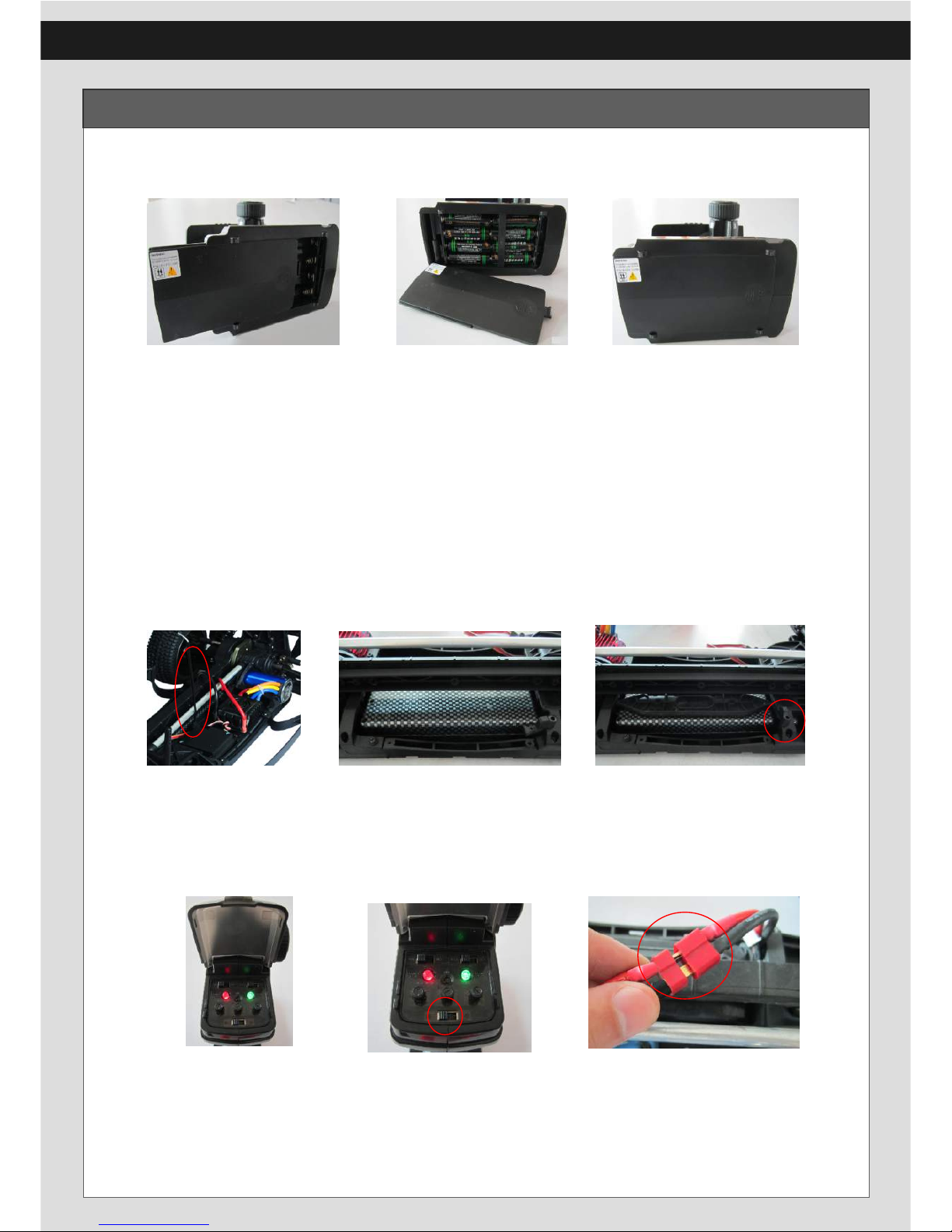
I、Driving Procedure
1. Open the cover of transmitter.
2. Insert the battery (pay attention to negative and positive).
3. Close the cover of transmitter.
Attention: It is suggested to use AA1.5V Alkaline battery in order
to achieve a better performance for transmitter. Please
don’t mix the new and old battery. Please take off the
battery from the transmitter if not to use.
4. Install antenna tube correctly.
5. Put the battery into the slot.
6. Close the battery tray.
7. Turn the throttle button and steering trim button to the middle position, and then
±120°.
8. Please turn on the transmitter first and then turn on switch of ESC. After
connecting, there is sound from motor, it means motor is standby.
Page 6
6
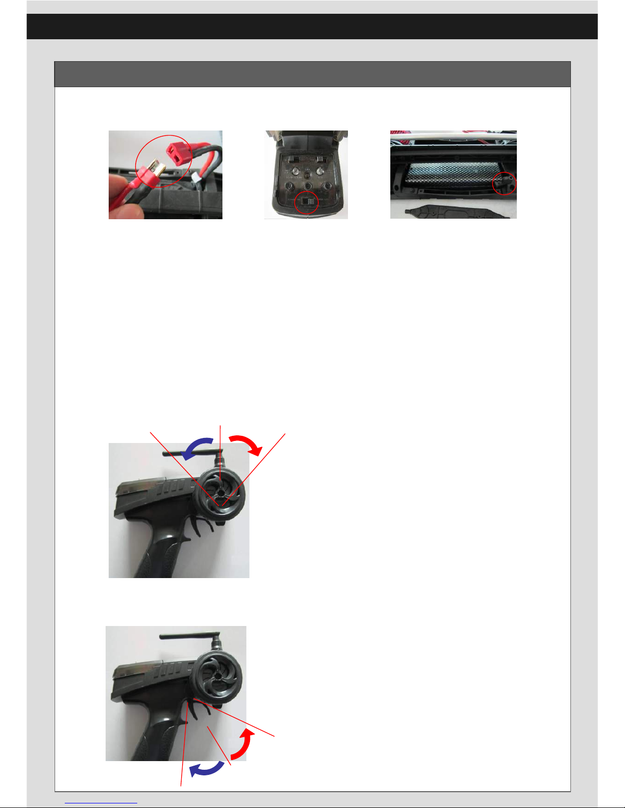
II、Finishing Driving
1. Turn off the ESC switch, and then disconnect the power.
2. Turn off the transmitter.
3. Take off the battery.
Driving Procedure
III、Transmitter adjustment
Turn on the transmitter first, connect the output plug of
battery and input plug of ESC, then turn on the ESC switch
(please pay more attention to positive and negative). You
will hear tone or the light will flash.
IV、Steering Control Method
V、Throttle Control Method
1. Rotate the steering wheel to the
left and right, the vehicle will also
have the corresponding steering.
The direction for the steering
wheel and car is the same.
2. Please adjust the neutral button
when the vehicle is not driven straightly.
1. Push down the throttle, the vehicle will
move forward.
2. When push up the throttle, the vehicle will
brake. The vehicle will move backward
when doing action of brake-neutral-brake.
3. When pushing the throttle, the vehicle has
no action (with Di-Di-Di sound), but the
steering function is normal, you should
adjust the throttle neutral button.
Brake
Backward
Forward
Page 7
7
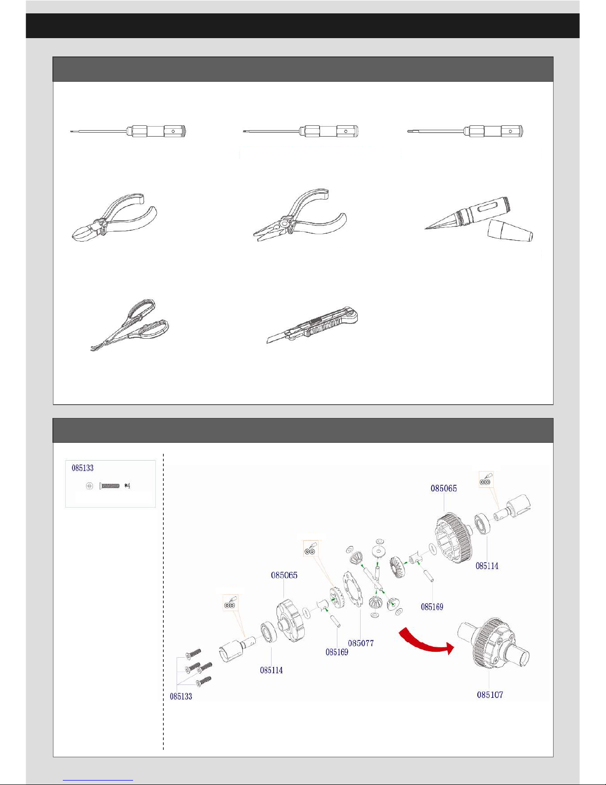
Recommended Maintenance Tools
Differential Build X 2
M3 X 16 Countersunk Phillips
Self-tapping Screws
Add grease
Add grease
Add grease
1.5mm Hex Screwdriver 2.0mm Hex Screwdriver 2.5mm Hex Screwdriver
Diagonal Cutting Plier Needle-nose Plier Reamer
Bend Scissors Knife
Page 8
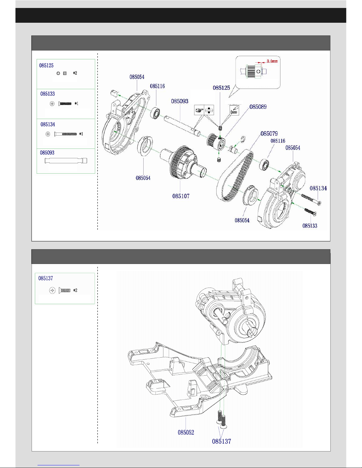
8
Front Gear Box Build
Front Gear Box Assembly
M3 X 16 Countersunk Phillips
Self-tapping Screws
M3 X 28 Countersunk Phillips
Self-tapping Screws
Front Shaft
Set Screw Should
be tighten on the flat
place
Add thread lock
15T Belt gear installing
M4 X 14 Countersunk Phillips
Self-tapping Screws
M4 X 4 Set Screw
Page 9
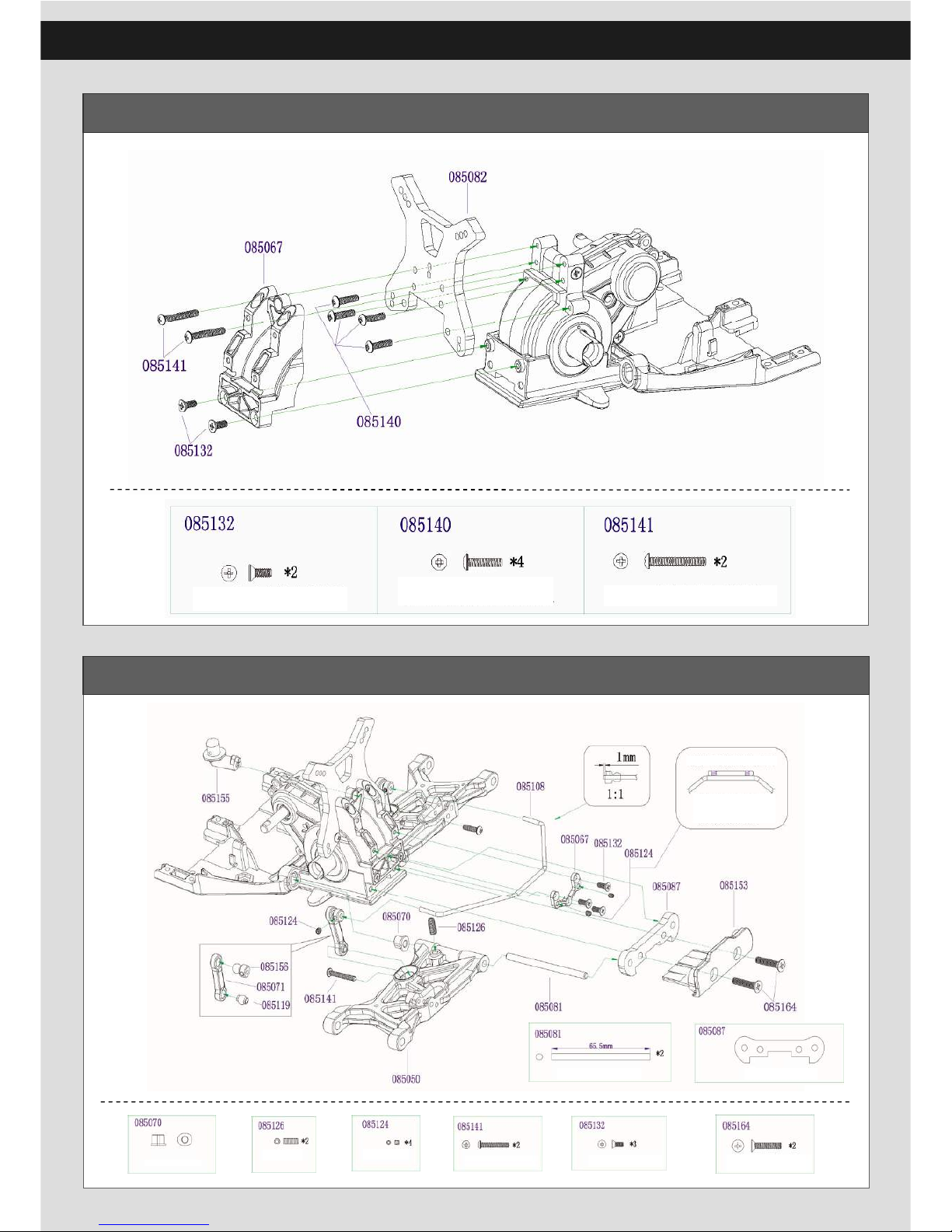
Front Shock Tower Assembly
Front lower Arm/Front Sway Bar Assembly
9
M3 X 8 Countersunk Phillips
Self-tapping Screws
M3 X 12 Button Phillips Selftapping Screws
M3 X 20 Button Phillips Selftapping Screws
Set screw and
Sway-bar installing
The set screw is only
used for sway-bar
adjustment, not againest
to sway-bar movement.
Fronr lower arm plate
Arm pin bushing
M3 X 8 Countersunk Phillips
Self-tapping Screws
M3 X 20 Button Phillips
Self-tapping Screws
Lower Arm Pin A
M4 X 20 Countersunk Phillips
Self-tapping Screws
M3 X 3 Set screw
M4 X 10 Set screw
Page 10

10
Steering Knuckle Assembly
Front Upper Link Assembly
Front lower arm
bushing
C-Mounting
Bushing
M4 X 18 Button Phillips
Machine Screws
CVD Drive shaft
Out Drive
M3 X 16 Button Phillips
Machine Screws
Page 11
11
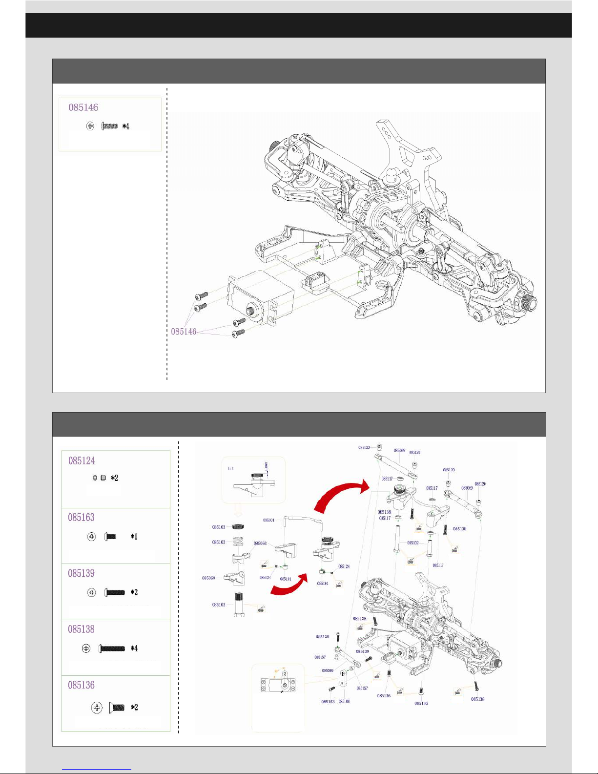
Servo Assembly
Steering Set Assembly
M3 X 10 Button Phillips
Machine Screws
M3 X 3 Set Screws
M3 X 12 Button Phillips
Machine Screws
M3 X 16 Button Phillips
Machine Screws
M4 X 10 Countersunk Phillips
Machine Screws
Add grease
Add grease
The Servo Installing:
1.linking the servo and tansmi tter,find the neutral.
2.put the servo arm into the servo gear,the servo arm
should be vertical to the ser vo.
3.tighten the screws
M3 X 6 Button Phillips
Machine Screws
Add grease
Add grease
Add grease
Add grease
Add grease
Add thread lock
Add grease
Add grease
Page 12
12
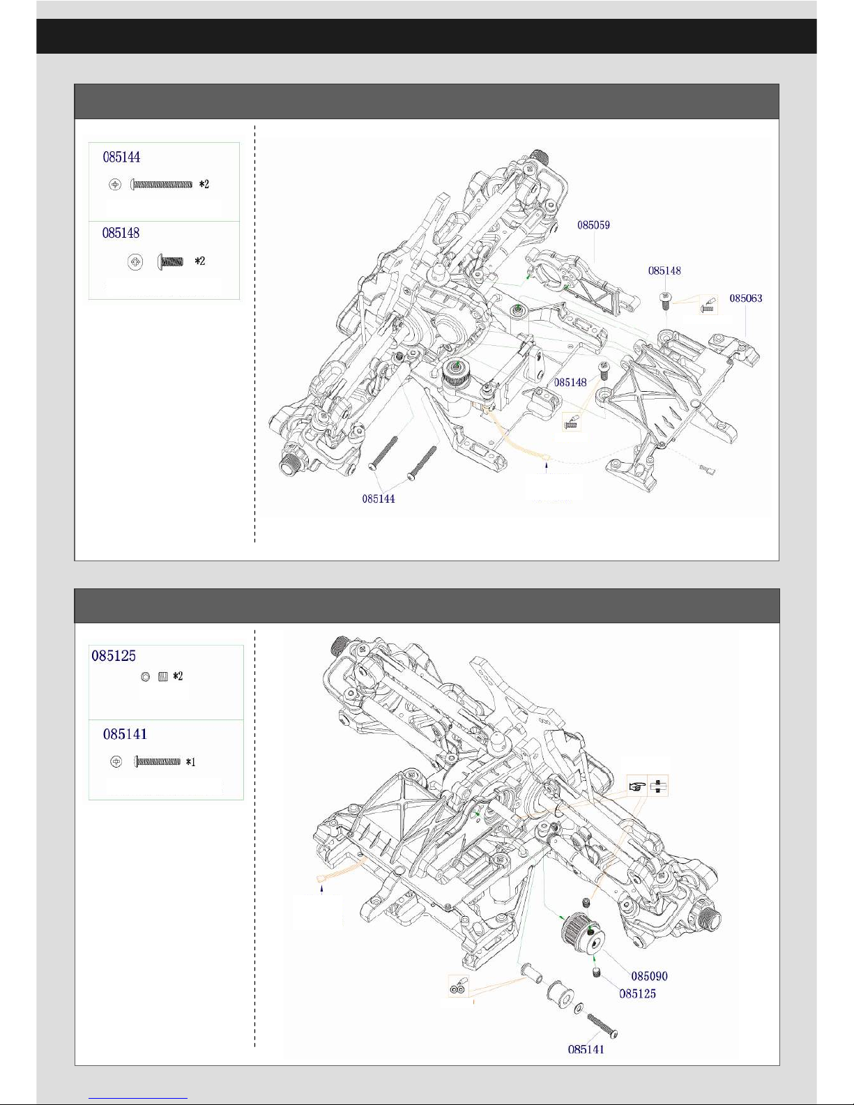
Front Upper Plate Assembly
Front Belt Gear Assembly
M3 X 28 Button Phillips
Machine Screws
M4 X 10 Button Phillips
Machine Screws
Servo Wires
Add thread lock
Add thread lock
M4 X 4 Set Screw
M3 X 20 Button Phillips
Self-tapping Screw
Servo Wires
Set screw should be
tighten on the flat place.
Add grease
Page 13
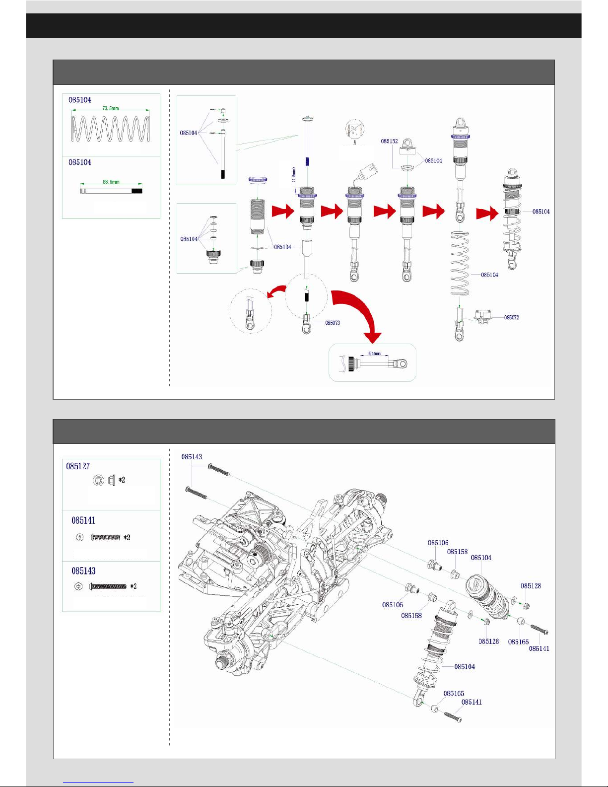
13
Front Shock Build
Front Shock Assembly
Front Shock Spring
Front Shock Shaft
No Bubble
more than
M3 Step Lock Nut
M3 X 20 Button Phillips Selftapping Screws
M3 X 26 Button Phillips
Machine Screws
Page 14
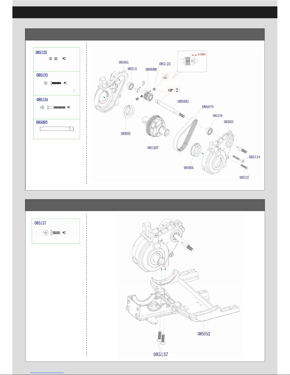
14
Rear Gear Box Build
Rear Gear Box Assembly
M4 X 4 Set Screw
M3 X 16 Countersunk
Phillips Self-tapping Screws
M3 X 28 Countersunk Phillips
Self-tapping Screws
Front Shaft
15T Gear Installing
Add thread lock
Set screw should be tighten
on the flat place
M4 X 14 Countersunk Phillips
Self-tapping Screws
Page 15
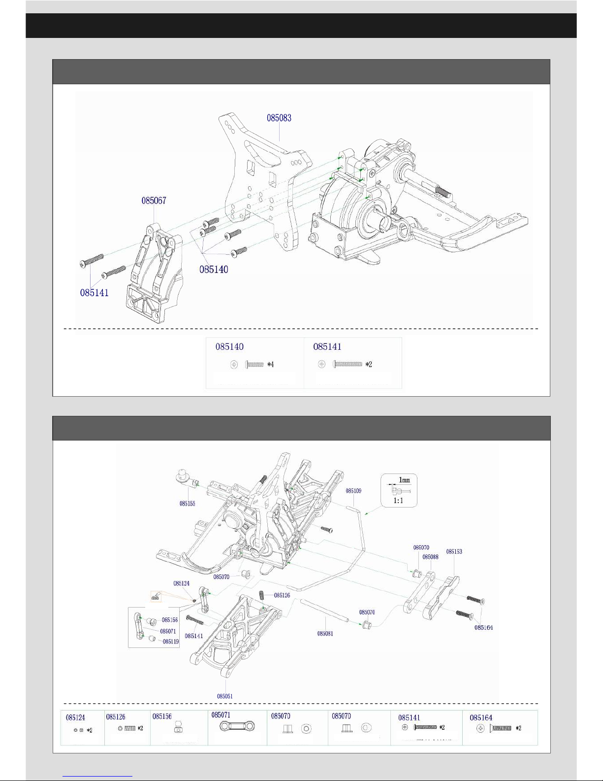
15
Rear Shock Tower Aseembly
Rear Lower Arm /Rear Sway Bar Assembly
M3 X 12 Countersunk Phillips
Self-tapping Screws
M3 X 20 Countersunk Phillips
Self-tapping Screws
Add grease
M3 X 3 Set Screw
M4 X 10 Set Screw
Sway Bar Upper Ball
Suspension Arm
Pin Bushing
Rear Suspension Arm
Pin Bushing(Rear)
M3 X 20 Button Phillips
Machine Screws
M4 X 20 Countersunk
Phillips Machine Screws
Sway Bar Mounting
Page 16
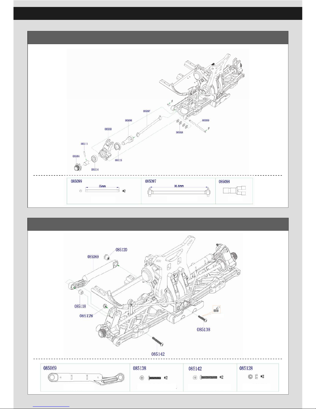
16
Rear Hub Carrier Build
Rear Upper Turnbuckle Assembly
Rear lower Suspension Arm Pin B
Rear Driver Shaft
Rear Axle
Add grease
Rear Upper Turnbuckle
M3 X 16 Button Phillips
Machine Screws
M3 X 22 Button Phillips
Machine Screws
M3 Lock Nut
Page 17
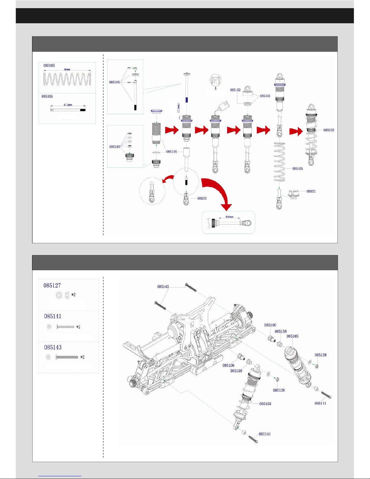
17
Rear Shock Build
Rear Shock Assembly
Rear Shock Spring
Rear Shock Shaft
More than
No Bubbles
M3 X 20 Button Phillips
Self-tapping Screws
M3 Step Lock Nut
M3 X 26 Button Phillips
Machine Screws
Page 18
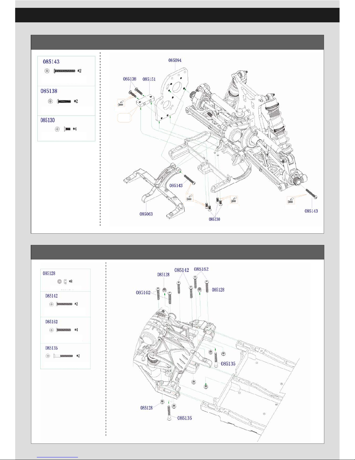
18
Motor Mount Assembly
Front Suspension Assembly
M3 X 26 Button
Phillips Machine Screws
M3 X 16 Button Phillips
Machine Screws
M3 X 8 Countersunk Phillips
Self-tapping Screws
This part is
upgrade part
Add thread lock
Add thread lock
Add thread
lock
Add thread lock
M3 Lock Nut
M3 X 22 Button Phillips
Machine Screws
M3 X 20 Button Phillips
Machine Screws
M3 X 28 Countersunk
Phillips Machine Screws
Page 19
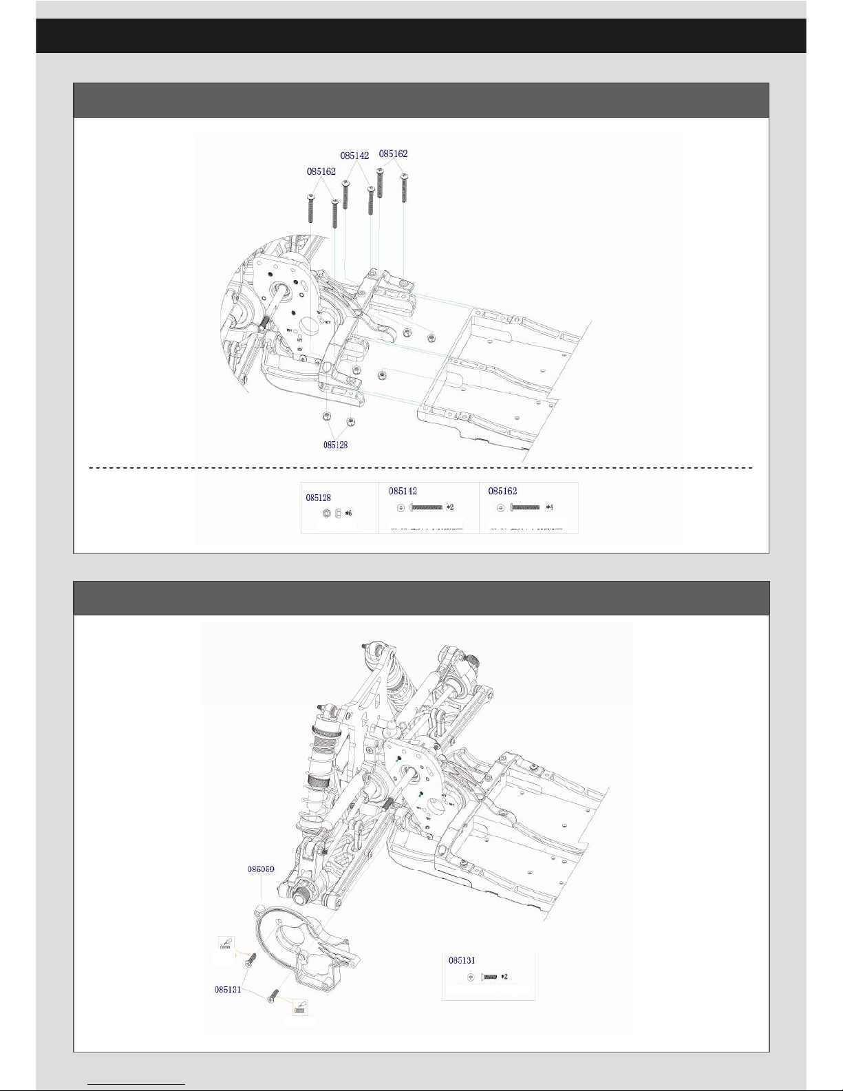
19
Rear Suspension Assembly
Rear Belt Box Assembly
M3 Lock Nut
M3 X 22 Button Phillips
Machine Screws
M3 X 20 Button Phillips
Machine Screws
M3 X 12 Countersunk
Phillips Machine Screws
Add thread lock
Add thread lock
Page 20
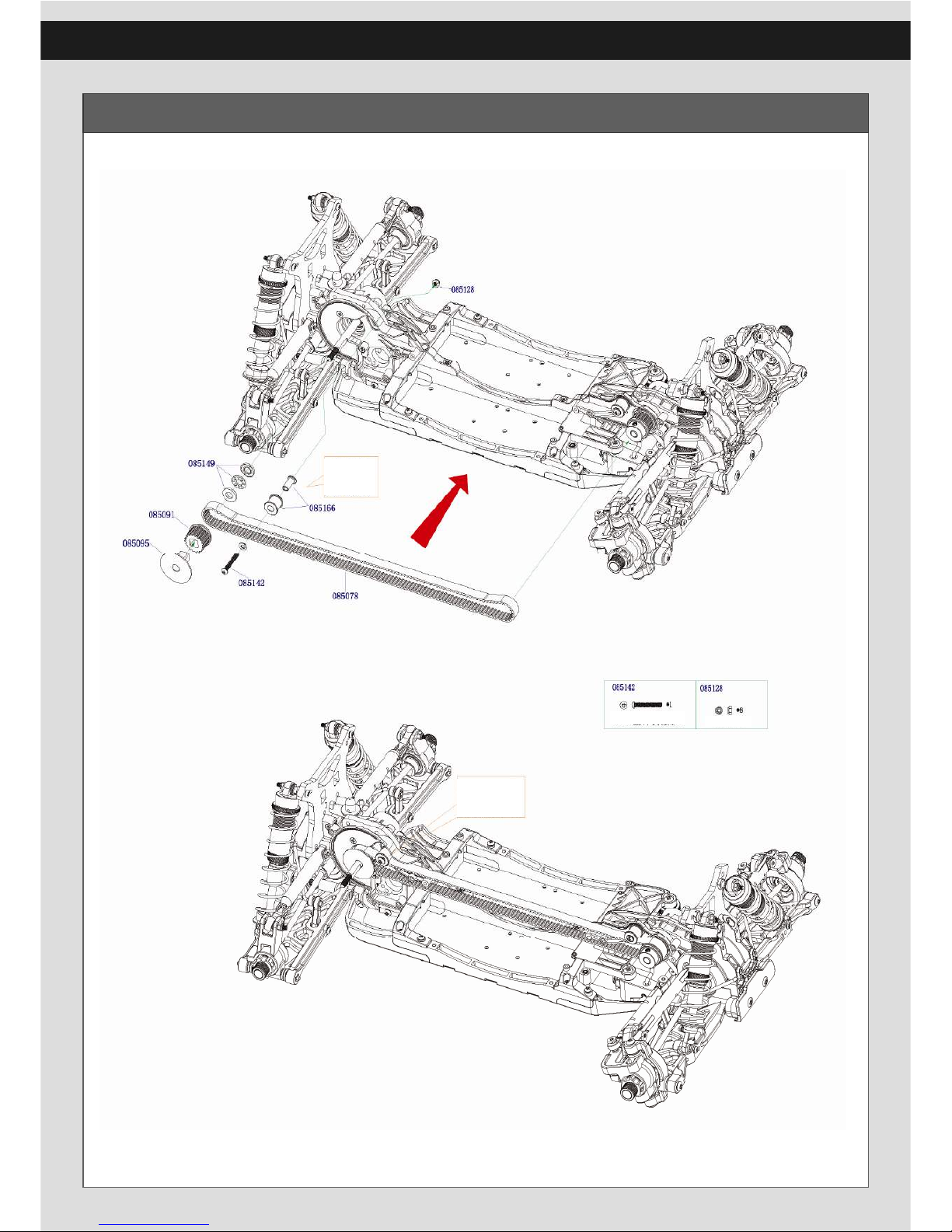
20
Middle Belt Assembly
Can Adjust
the belt
M3 Lock Nut M3 X 22 Button
Phillips Machine
Screws
Can Adjust
the belt
Page 21
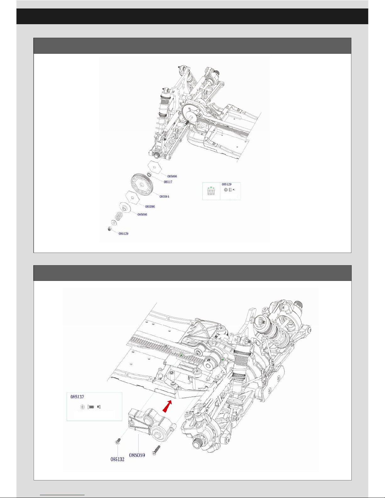
21
65T Main Gear Assembly
Front Belt Box Assembly
M4 Lock nut
M3 X 8 Countersunk Phillips
Self-tapping Screws
Main Gear
Spring
Page 22
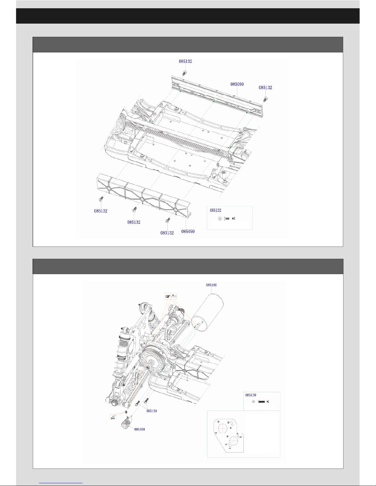
22
Middle Belt Box Assembly
Motor Assembly
M3 X 8 Countersunk
Phillips Self-tapping Screws
Set Screw should be
tighten on the falt place
M3 X 12 Button Phillips
Machine Screws
Motor Mounting:
1.it can install 15T or 17
T pinion gear,but please
use the appropriate
mounting hole for the
different pinion gear.
2.it can install different
diameter motor,
36mm(standard),40mm
(option),42(option).
Add thread lock
Page 23
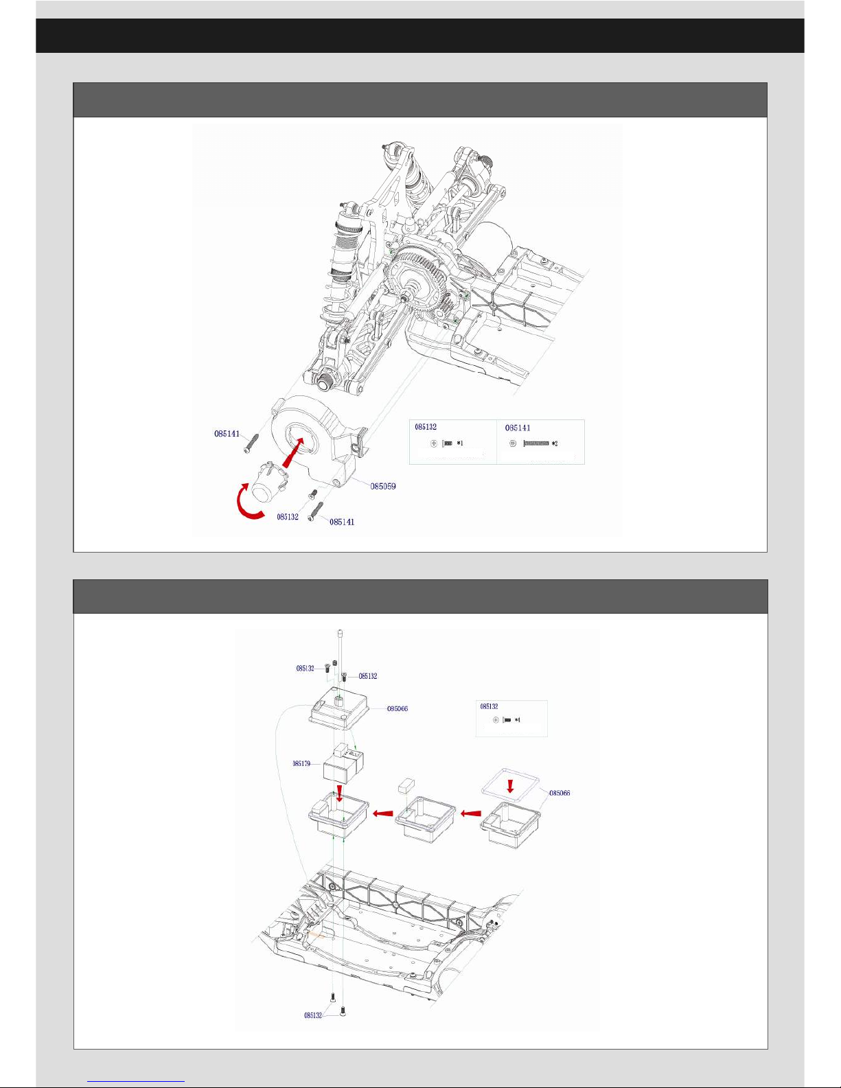
23
Rear Belt Box Assembly
Receiver Box Assembly
M3 X 8 Countersunk
Phillips Self-tapping Screws
M3 X 20 Button Phillips
Self-tapping Screws
M3 X 8 Countersunk
Phillips Self-tapping Screws
Page 24
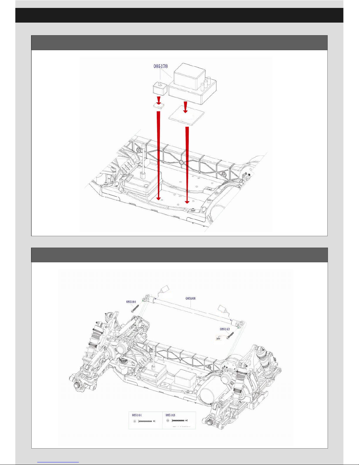
24
ESC Assembly
Middle Brace Assembly
AB Glue
Please use AB glue
Add thread lock
M3 X 28 Button Phillips
Self-tapping Screws
M3 X 26 Button Phillips
Self-tapping Screws
Please use AB glue
AB Glue
Double side tape
Double side tape
Page 25
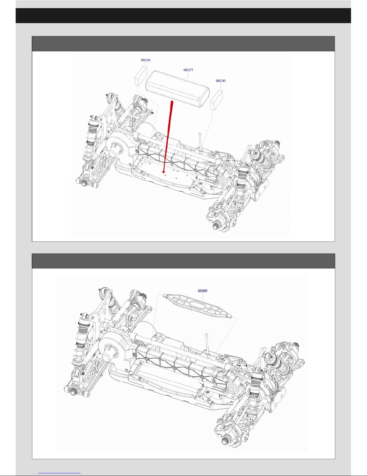
25
Battery Assembly
Battery Tray Assembly
Page 26
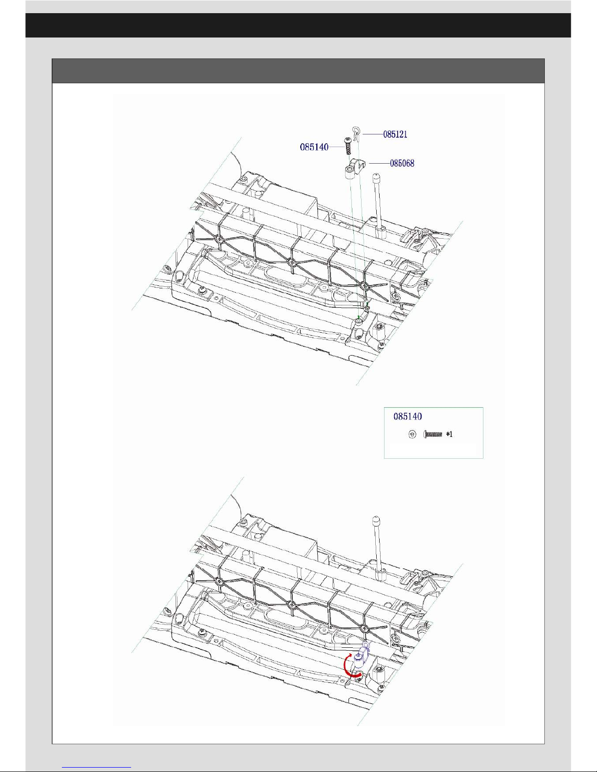
26
Battery Tray Button Assembly
M3 X 12 Button Phillips
Self-tapping Screws
Page 27
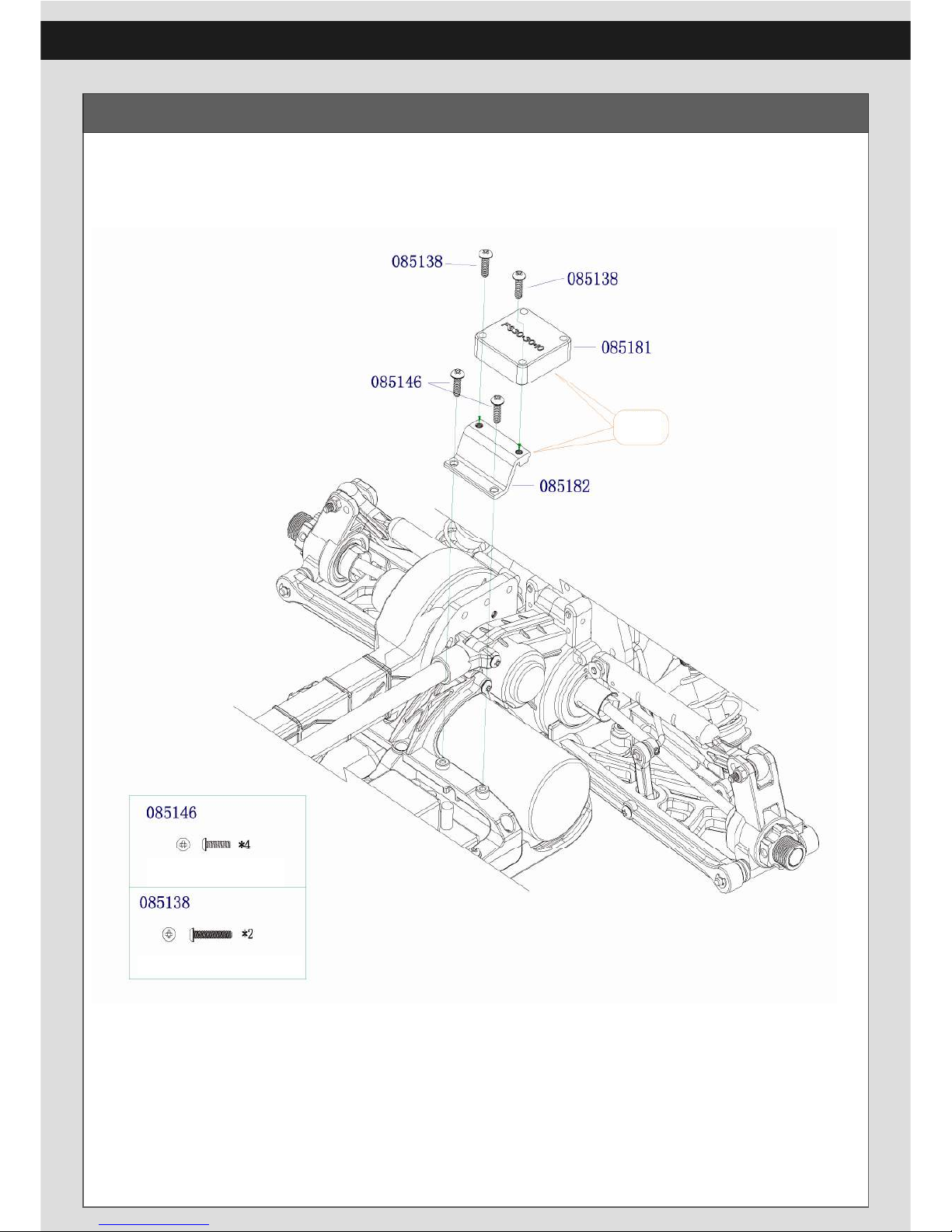
27
Fan Brace Assembly
T parts are
option parts
M3 X 10 Button Phillips
Self-tapping Screws
M3 X 16 Button
Phillips Machine Screws
Page 28
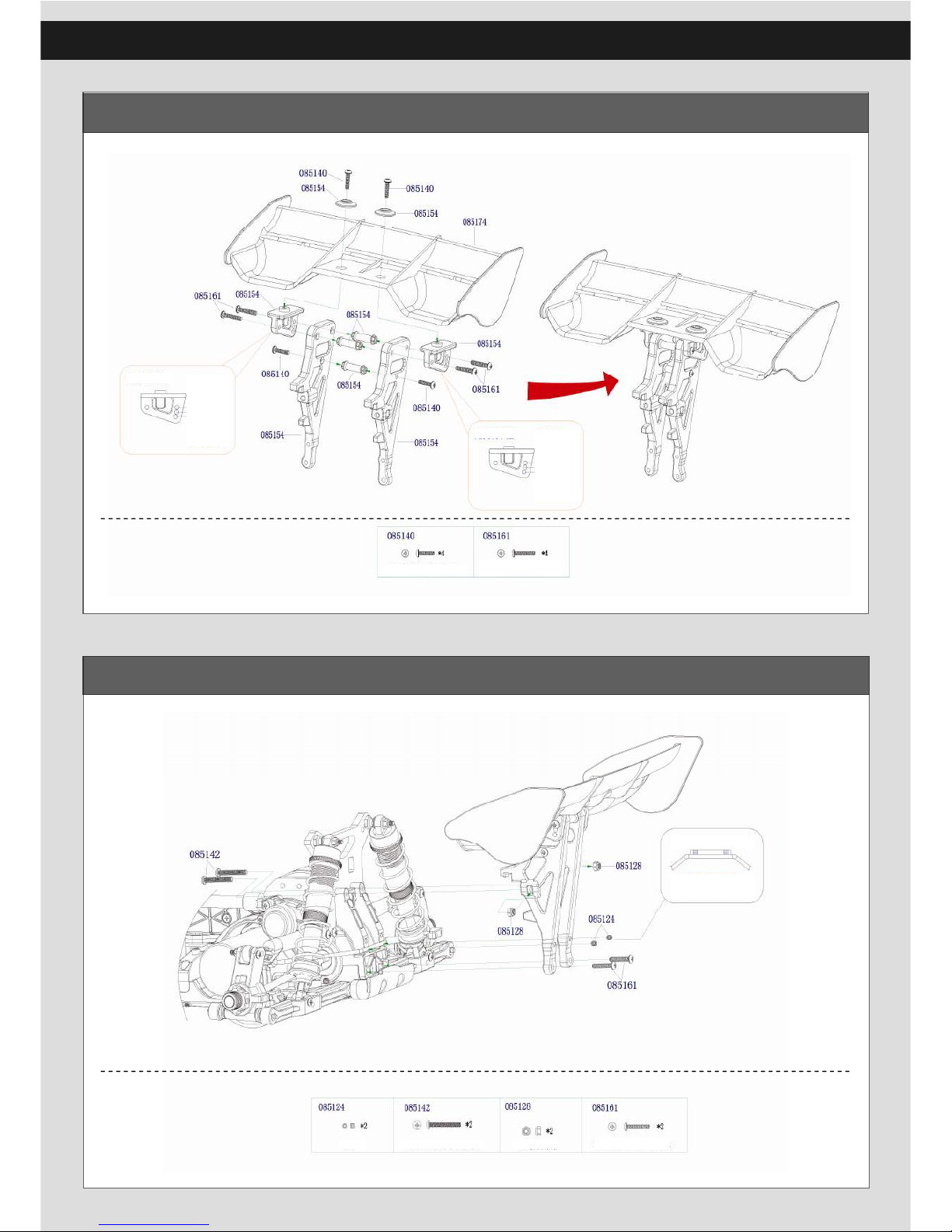
28
Tail Wing Build
Tail Wing Assembly
M3 X 16 Button Phillips
Self-tapping Screws
M3 X 12 Button Phillips
Self-tapping Screws
M3 X 3 Set screw
M3 X 22 Button Phillips
Machine Screws
M3 lock nut
M3 X 16 Button Phillips
Self-tapping Screws
Page 29
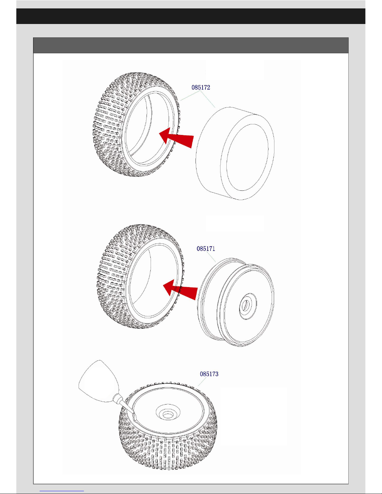
29
Tire Build
Put the insert into the tire
Put the tire on the rim .
Drop the CA glue into the
gap between the tire and rim .
CA Glue
Page 30
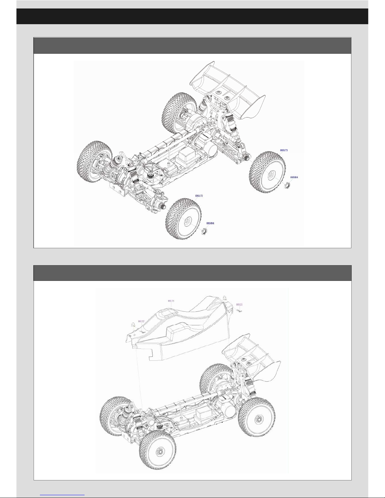
30
Tire Assembly
Bodyshell Assembly
Page 31
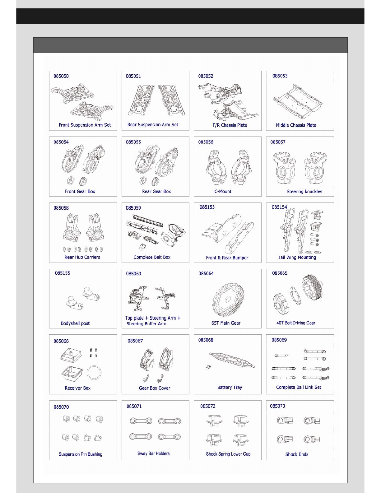
31
Spare Part List
Page 32
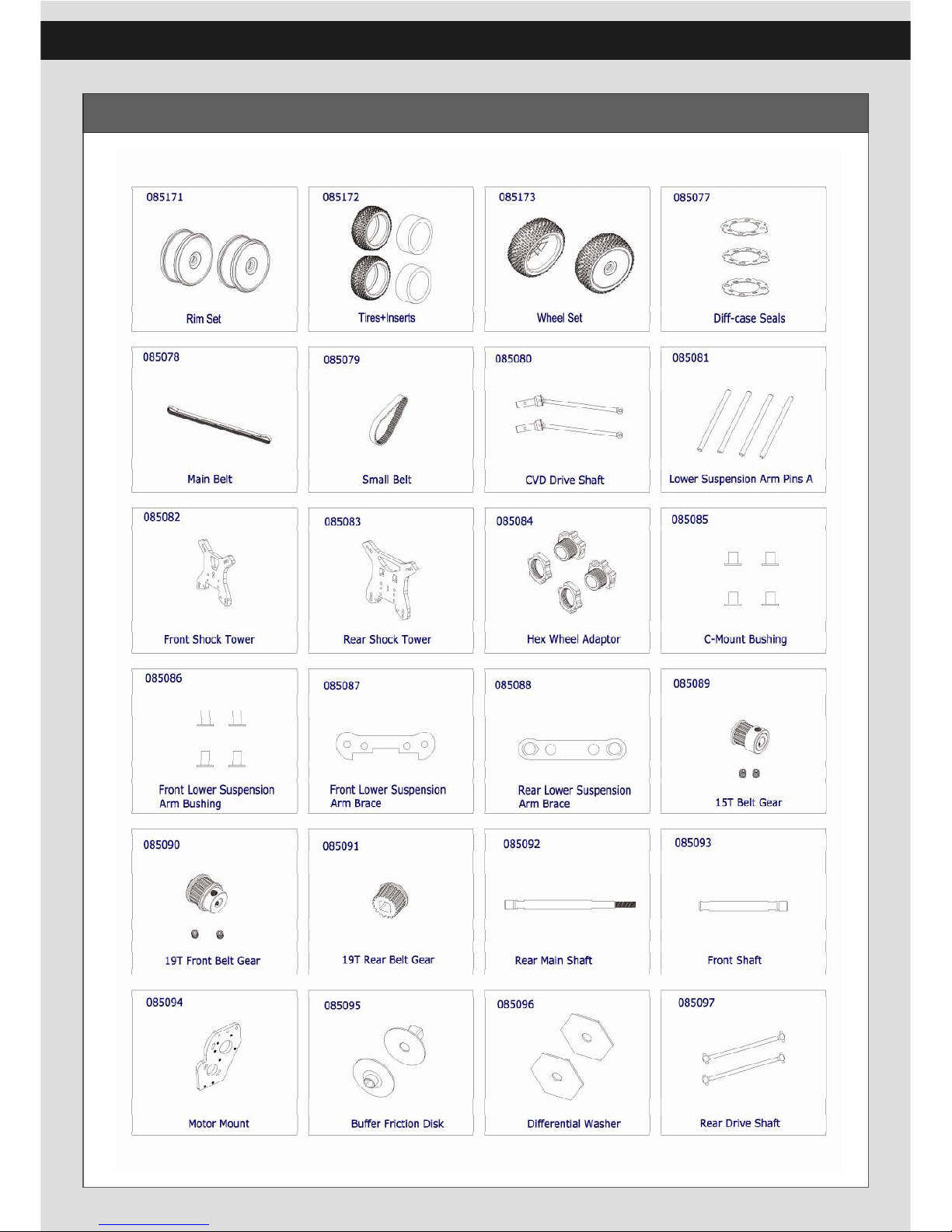
32
Spare Part List
Page 33
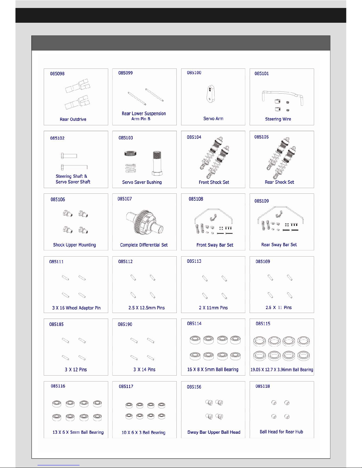
33
Spare Part List
Page 34
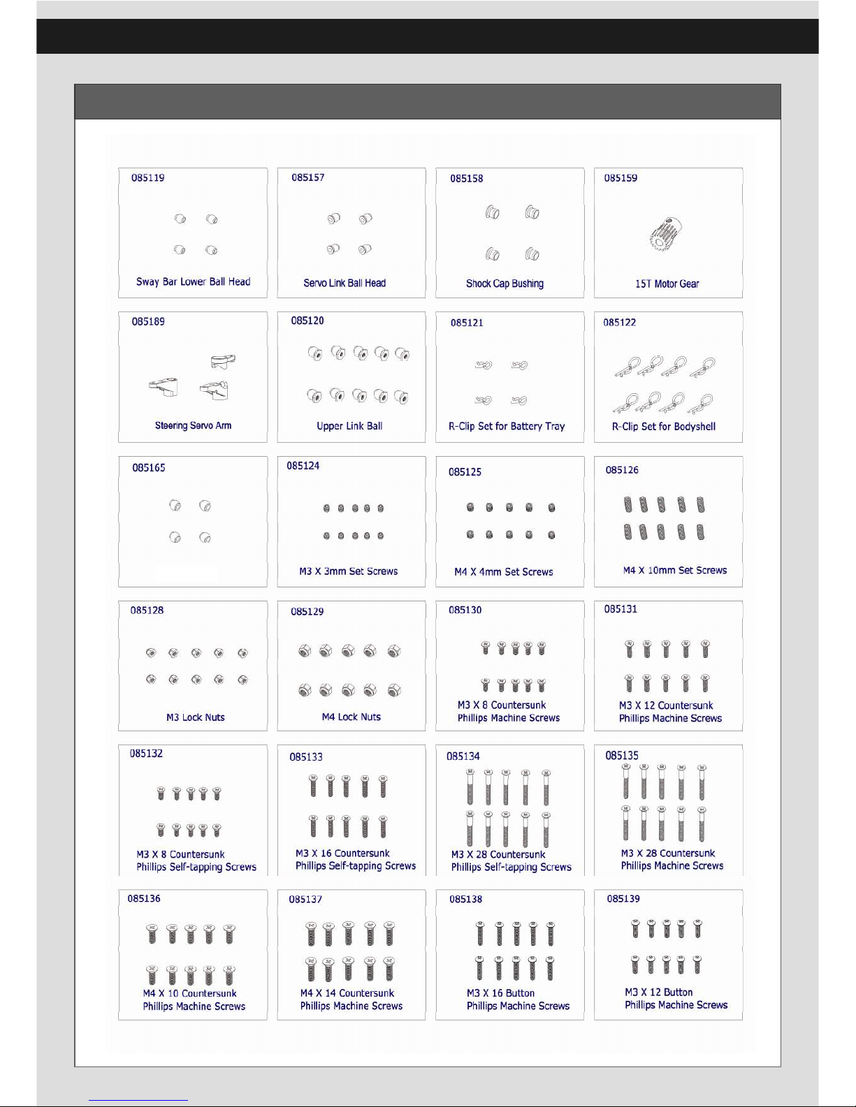
34
Spare Part List
Ball Head of Shock Ends
Page 35
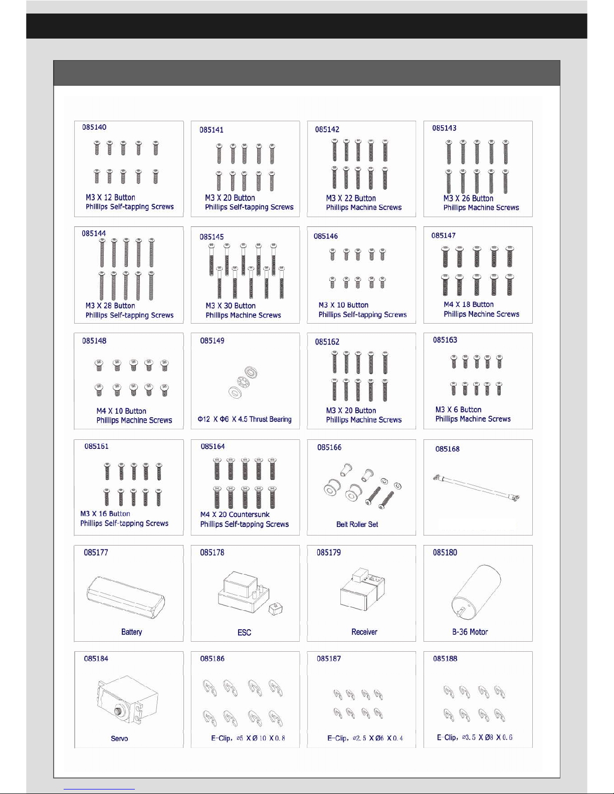
35
Spare Part List
Glass Fiber
Page 36
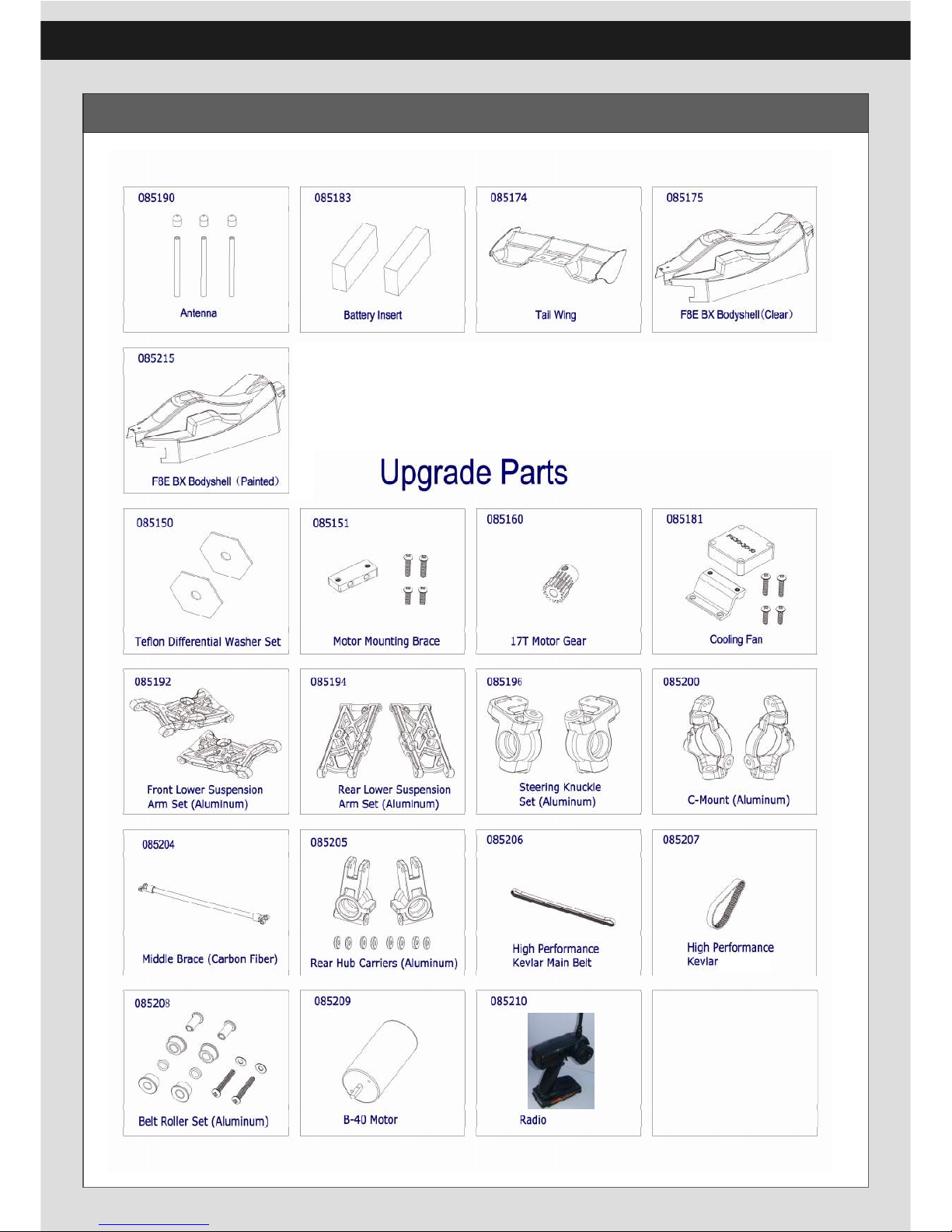
36
Spare Part List
Small Belt
Ball Head of Shock Ends
Page 37
37
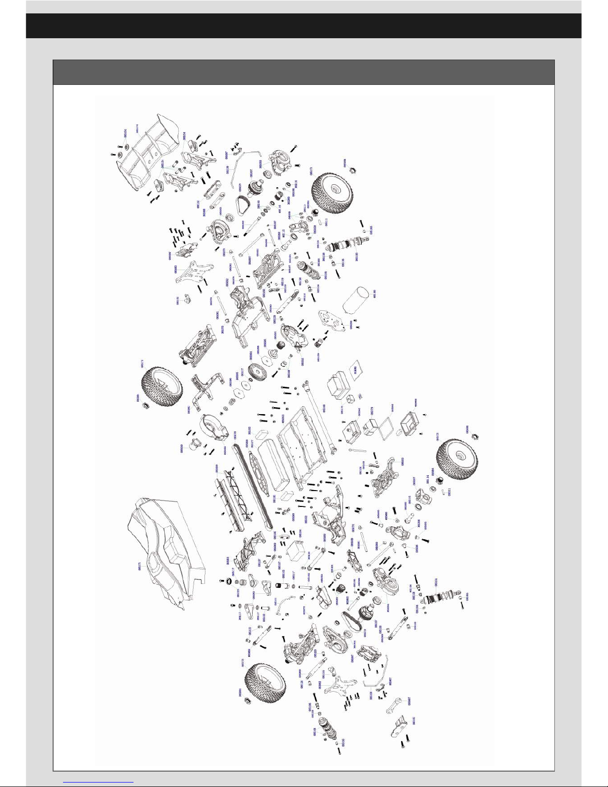
F8E-BX Exploded View
Page 38

福瑞达模型有限公司
DONGGUAN FREERCHOBBY CO.,LTD
TEL/FAX :+86-769-82927540
www.freerchobby.com
Thank you
 Loading...