

Page 1

1
FreePP MPES-4
User Guide V1.13
Model: BV1201
Page 2

2
Copyright
© 2005-2008 FreePP Inc. All rights reserved.
This user guide and the software described in it are copyrighted with all rights reserved. No part of this publication may be
reproduced, transmitted, transcribed, stored in a retrieval system, or translated into any language in any form by any means without
the written permission of FreePP Inc.
Notice
FreePP reserves the right to change specifications without prior notice.
While the information in this manual has been compiled with great care, it may not be deemed an assurance of product
characteristics. FreePP shall be liable only to the degree specified in the terms of sale and delivery.
The reproduction and distribution of the documentation and software supplied with this product and the use of its contents is subject
to written authorization from FreePP Inc.
Specific trademark usage guidelines
1. Logos. You may not use any FreePP logos (including buttons and graphic symbols) without a trademark license from FreePP Inc.
All usage of trademark logos shall be pursuant to these guidelines and any other guidelines associated with that logo.
2. Merchandise items. You may not manufacture, sell, or give away merchandise items bearing FreePP trademarks or logos,
except pursuant to and express written trademark license from FreePP Inc.
3. Slogans and taglines. You may not use or imitate a FreePP slogan or tagline such as "Voice beyond Sky".
Page 3

3
How to Use this Guide
This guide has been written to be understood easily and the following typographic conventions and symbols are used throughout this
document:
Very important information. Failure to observe this may result in damage.
Important information that should be observed.
Additional information that might be helpful.
Help Us to Improve this Document
Should you find any mistakes in this document or want to provide comments to improve the manual please send e-mail directly to:
FreePP Technical Support
If you have questions when installing or using this product, please go to FreePP website at www.freepp.com for:
Direct contact to the FreePP support centers.
Frequently Asked Questions (FAQ).
Feedback section to leave your message.
Download area for the latest software, user documentation and product updates.
Page 4

4
Table of Contents
Copyright...........................................................................................................................................................................................................2
Notice .................................................................................................................................................................................................................2
Specific trademark usage guidelines........................................................................................................................................................2
How to Use this Guide...................................................................................................................................................................................3
Help Us to Improve this Document............................................................................................................................................................3
FreePP Technical Support............................................................................................................................................................................3
Chapter 1: Introduction .......................................................................... 7
Chapter 2: Getting to Know the MPES-4 ........................................................... 8
Front Panel Connectors................................................................................................................................................................................8
Front Panel LED Indications........................................................................................................................................................................9
Back Panel Connectors...............................................................................................................................................................................10
Chapter 3: Connecting the MPES-4............................................................... 11
Overview.......................................................................................................................................................................................................... 11
Instructions for connecting the MPES-4.................................................................................................................................................12
Chapter 4: Getting started with accessing the MPES-4 ............................................. 14
Overview..........................................................................................................................................................................................................14
How to use FreePP Starter..........................................................................................................................................................................15
Access to your MPES-4...............................................................................................................................................................................16
Page 5

5
Chapter 5: Configuring the MPES-4 via Web Interface.............................................. 19
Overview..........................................................................................................................................................................................................19
Status & Log...................................................................................................................................................................................................24
Status & Log | Status Monitor................................................................................................................................................................25
Status & Log | Configuration..................................................................................................................................................................26
Status & Log | System Log....................................................................................................................................................................28
Status & Log | Call Log...........................................................................................................................................................................30
Networking......................................................................................................................................................................................................31
Networking | IP Settings.........................................................................................................................................................................32
Networking | IP Settings | DHCP Client...............................................................................................................................................33
Networking | IP Settings | Static IP.......................................................................................................................................................34
Networking | IP Settings | PPPoE Client..............................................................................................................................................36
Networking | HTTP proxy.......................................................................................................................................................................37
Telephony........................................................................................................................................................................................................38
Telephony | Port Setting.........................................................................................................................................................................40
Telephony | Call forwarding Setting......................................................................................................................................................41
Telephony | Localized Dialing Plan.......................................................................................................................................................45
Telephony | FXO Outbound Policy.......................................................................................................................................................47
Telephony | FXO Inbound Policy ..........................................................................................................................................................49
Telephony | Advanced Setting...............................................................................................................................................................51
Telephony | Analog Coefficients ............................................................................................................................................................53
Telephony | Analog Coefficients | Busy Tone Recognition................................................................................................................56
Telephony | Voice Volume Setting........................................................................................................................................................59
System .............................................................................................................................................................................................................60
System | System log Setting..................................................................................................................................................................61
Page 6

6
System | Time Setting.............................................................................................................................................................................62
System | NTP Setting .............................................................................................................................................................................63
System | Upgrade (Firmware Upgrade)...............................................................................................................................................65
System | Administrator Password.........................................................................................................................................................66
System | Reset (Restore to factory default)........................................................................................................................................67
System | System Reboot........................................................................................................................................................................68
Quick Setup....................................................................................................................................................................................................69
Quick Setup | IP Setting | DHCP Client...............................................................................................................................................71
Quick Setup | IP Setting | Static IP.......................................................................................................................................................72
Quick Setup | IP Setting | PPPoE Client..............................................................................................................................................74
Diagnostic.......................................................................................................................................................................................................75
Chapter 6: Making FreePP Calls.................................................................. 77
Place FreePP On-Net Calls.........................................................................................................................................................................77
Place FreePP Outbound Calls (FreePP OUT Service).........................................................................................................................77
Chapter 7: Adding FreePP Credit................................................................. 78
Add FreePP Credit to your FreePP account..........................................................................................................................................78
Chapter 8: Appendix ............................................................................ 79
FCC REQUIREMENTS..................................................................................................................................................................................79
Page 7
7
Chapter 1: Introduction
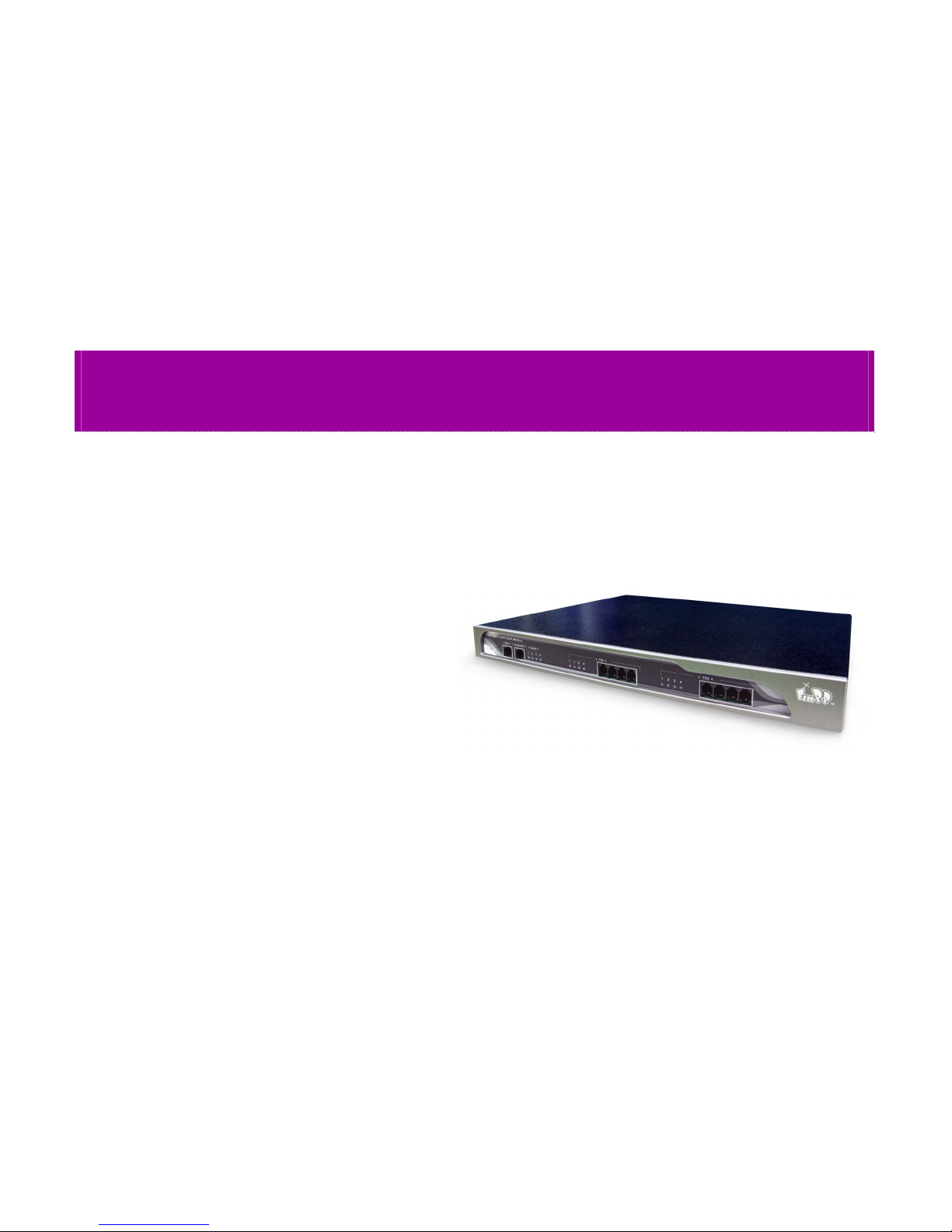
Thank you for choosing FreePP MPES-4. This MPES-4 will
allow you to make and receive phone calls through FreePP
network using your existing broadband connection. Our
MPES-4 is named BV1201, so BV1201 stands for this
MPES-4 here from in this Guide.
What’s in this Guide?
This user guide contains the steps for installing the BV1201.
z Chapter 1 Introduction
z Chapter 2 Getting to Know the MPES-4
z Chapter 3 Connecting the MPES-4
z Chapter 4 Getting Started with accessing the MPES-4
z Chapter 5 Configuring the MPES-4 via Web Interface
z Chapter 6 Making FreePP calls
z Chapter 7 Adding FreePP Credit
z Chapter 8 Appendix
Page 8
8
Chapter 2: Getting to Know the MPES-4
Front Panel Connectors
Connector Description
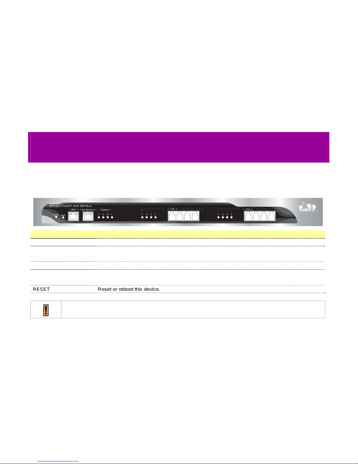
FXS(1-4) The four FXS ports allow you to connect the MPES-4 to the CO lines of PBX or telephone sets.
FXO(1-4) The four FXO ports allow you to connect the MPES-4 to the extension lines of PBX or to receive
plain old telephone service from PSTN.
Configuration The Configuration port allows you to change the settings of the MPES-4 by using FreePP Starter.
WAN The WAN port allows you to connect the MPES-4 to broadband Internet access, such as modem or
router using a Cat.5 Ethernet network cable.
RESET Reset or reboot this device.
The MPES-4 supports 4 voice ports. Each port can be configured as either FXS or FXO. You can do the
configuration via web management.
Page 9
9
When the reset button is pressed, the MPES-4 will reboot. When the reset button is pressed for 5 seconds, the
MPES-4 will reboot and go back to the default settings.
Front Panel LED Indications
LED Color Description
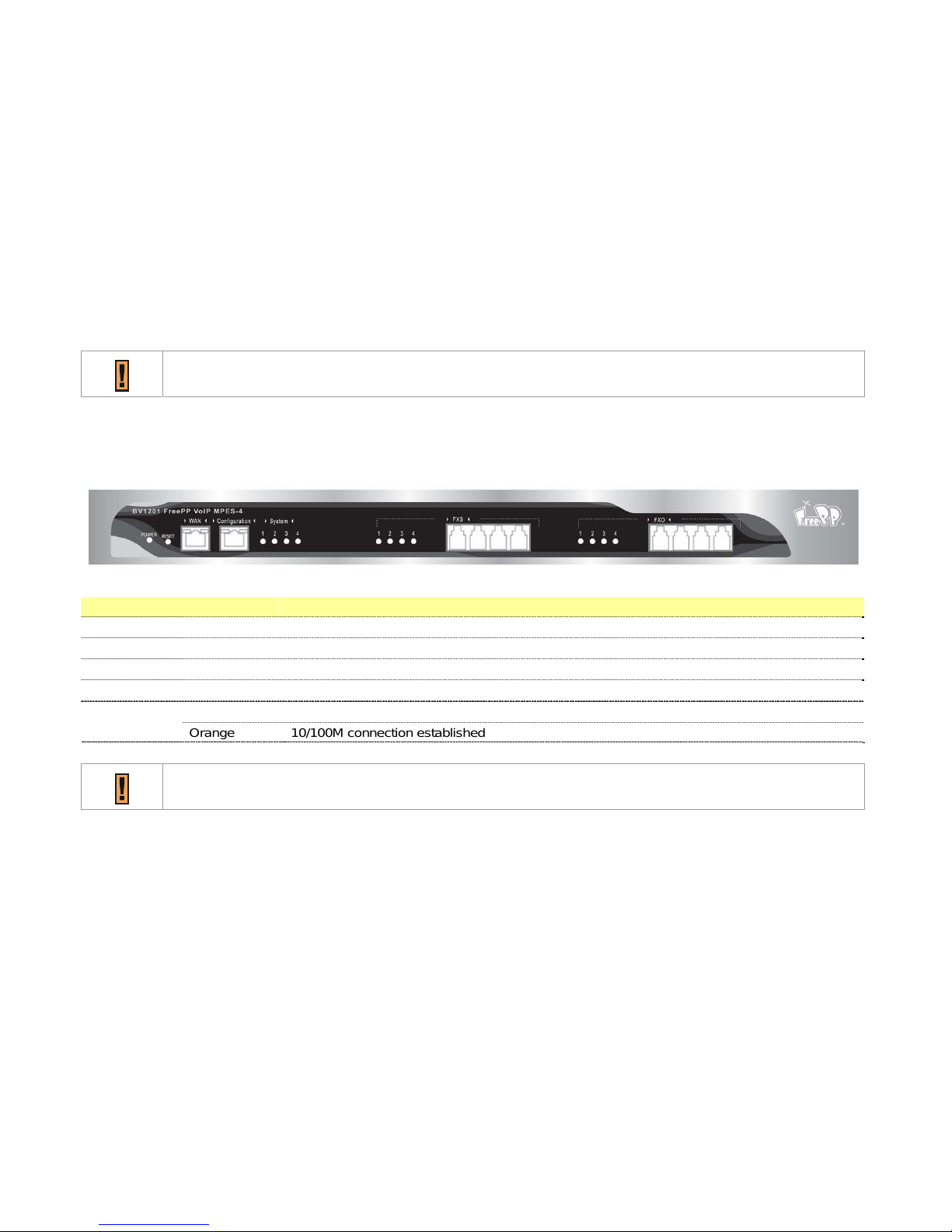
POWER Green It lights up when the MPES-4 is powered on.
FXS(1-4) Green They light up when FXS are in use. They go off when FXS are not in use.
FXO(1-4) Green They light up when FXO are in use. They go off when FXO are not in use.
System(1-4) Green They are solidly lit when registration to FreePP Server is successful.
Green Link and data transmission WAN
Orange 10/100M connection established
PBX stands for Private Branch eXchange.
Page 10
10
Back Panel Connectors
Port Description
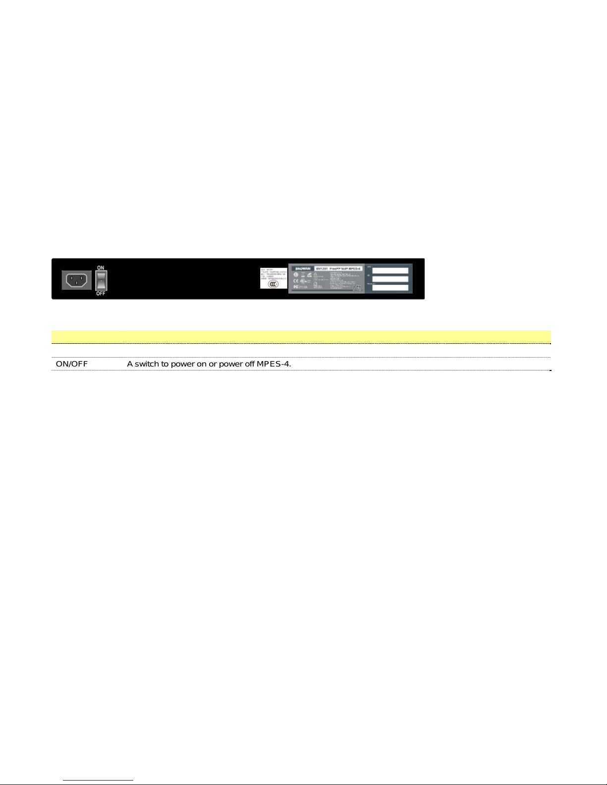
Power The power port is where you connect the included power cord to AC Outlet.
ON/OFF A switch to power on or power off MPES-4.
Page 11
11
Chapter 3: Connecting the MPES-4
Overview
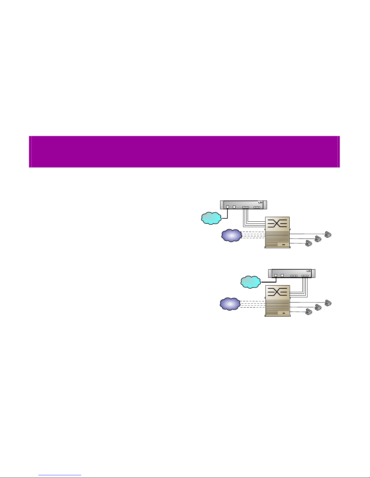
This chapter gives connection guidelines on how to
connect FreePP MPES-4 to your network and PBX. A
typical connection diagram is shown on the right.
Page 12
12
Instructions for connecting the MPES-4
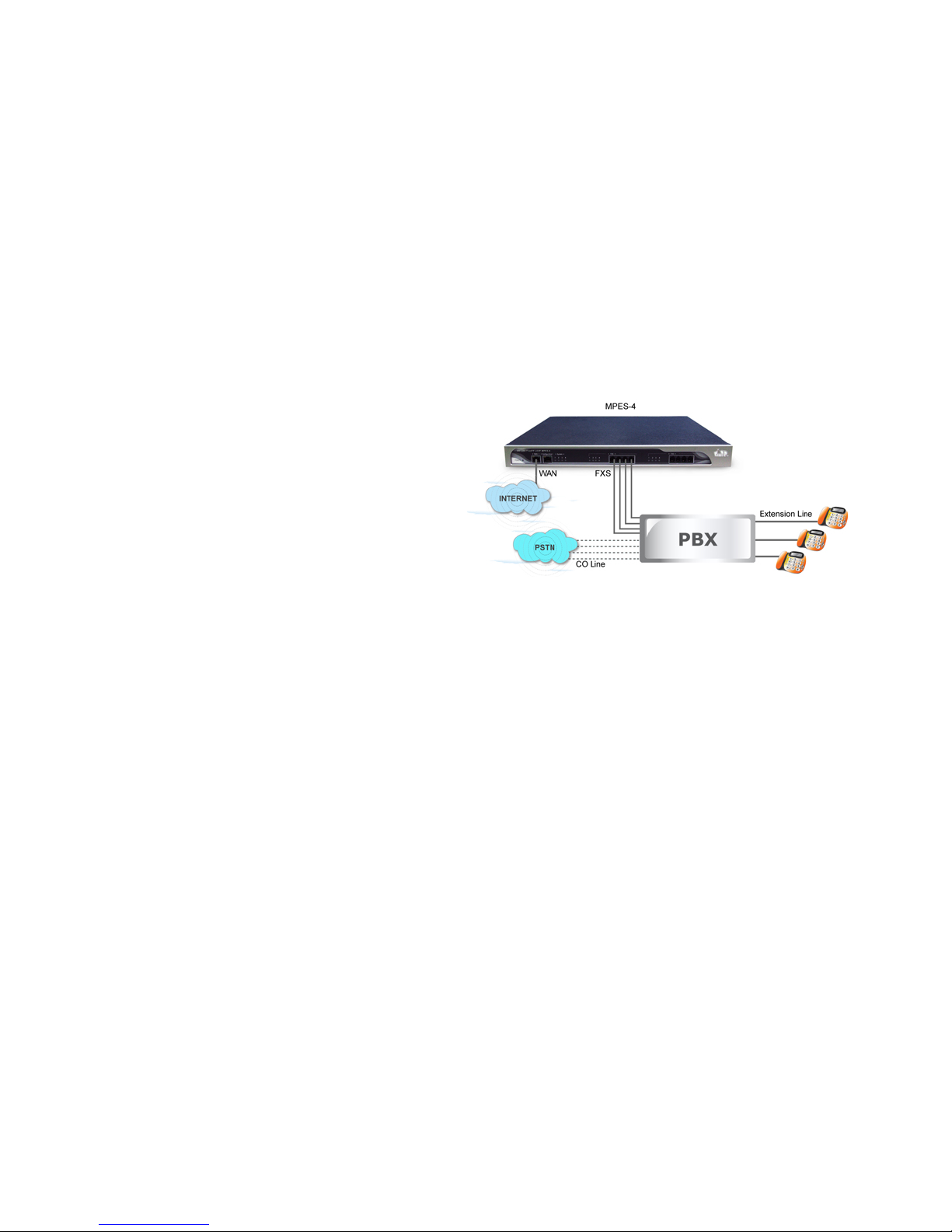
There are two ways to connected the MPES to PBX:
1. FXS port of MPES connected to FXO port of PBX.
Step1.
Plug the AC cord in and turn the switch to on.
Step2.
Connect the WAN port of MPES to ADSL/Cable modem
with network cable.
Step3.
Connect the FXS port of MPES to FXO port of PBX with
phone cable.
Page 13

13
2. FXO port of MPES connected to FXS port of PBX.
Step1.
Plug the AC cord in and turn the switch to on.
Step2.
Connect the WAN port of MPES to ADSL/Cable modem
with network cable.
Step3.
Connect the FXO port of MPES to FXS port of PBX with
phone cable.
The MPES-4 can work properly without PC/Laptop except for changing the settings.
In some particular network, MAC authentication is enabled, so you have to inform the network administrator about the
MAC address of your MPES-4.
If the system light is green, it means the registration connection is successful.
There are two possible reasons for the registration failed issue
1) The MPES-4 is not activated by FreePP, and 2) the network configuration of MPES-4 is incorrect.
For the reason 1, please contact customer service representative. For the reason 2, please refer to the Chapter 5
Configuring the MPES-4 via WEB Interface.
Page 14
14
Chapter 4: Getting started with accessing the MPES-4
Overview
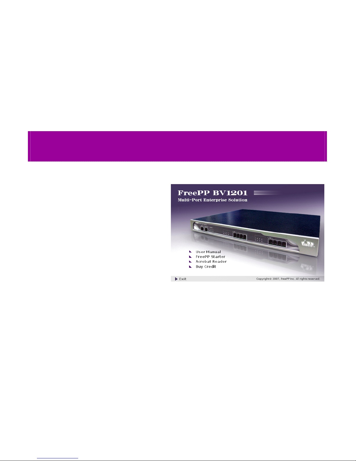
You can configure the MPES-4’s network settings via web
interface. For the first web browser, please launch the
FreePP Starter utility that is provided with your product CD.
Page 15
15
How to use FreePP Starter
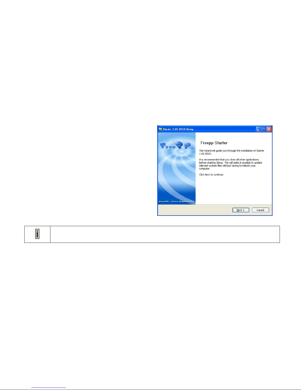
The FreePP Starter is a software utility that is included on the
Product CD.
The utility automatically detects FreePP devices installed on
your network, regardless of its host IP address and lets you
configure each unit’s IP settings. It provides quick access to
your MPES-4 via HTTPS.
To install the FreePP Starter utility, please insert the
Installation CD into your CD-ROM driver. Find and install the
utility from the product CD into the computer.
If the Installation CD does not start automatically, pleas e run “ BV1201.exe” manually from the root directory of the
installation CD.
Page 16
16
Access to your MPES-4
To access web management page, please launch the FreePP
Starter utility that is provided with your product CD. The
following are the instructions:
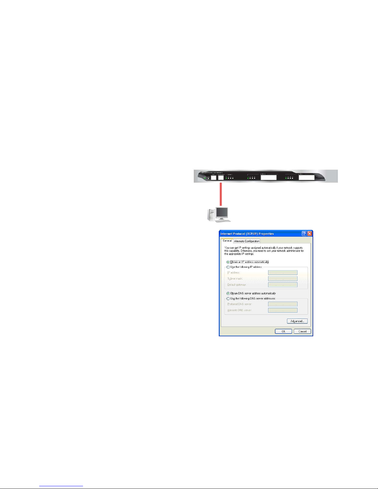
1. Connect the Configuration port of MPES to your
computer with the Ethernet cable.
2. Set your IP address in local area network of computer as
Obtain an IP address automatically.
Page 17
17
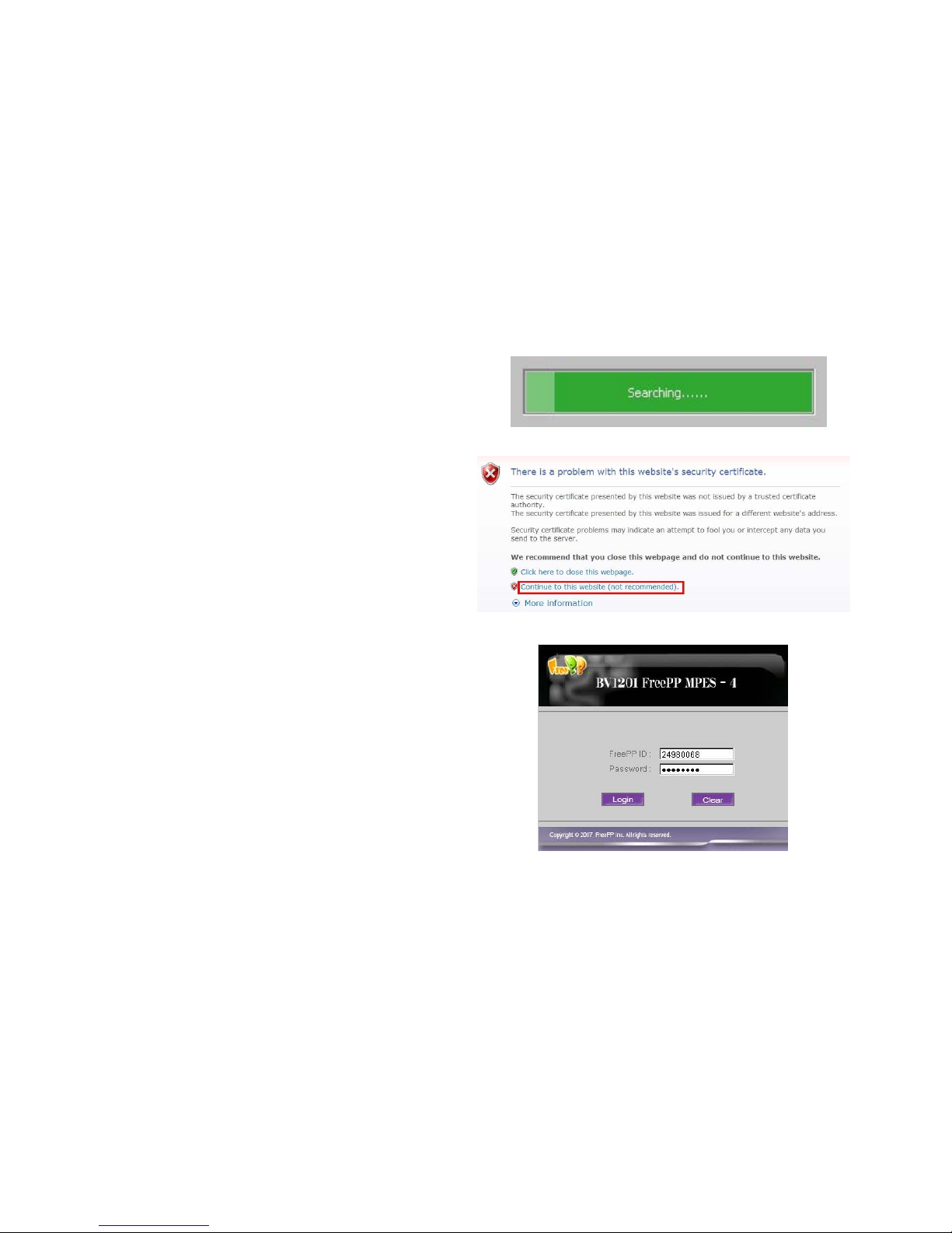
3. Install the FreePP Starter utility from the Inst allation C D.
Click Start > Programs > FreePP > Starter > FreePP
Starter to launch the application. If the MPES-4 is
connected to your network, the utility will find your
MPES-4 automatically.
4. Select continue to this website in security certificate
window to launch the web management interface through
the secure https connection.
5. Enter the MPES-4 login settings to access the web
management interface.
FreePP ID You can find the FreePP ID number at the
bottom of the MPES-4.
Password You can find the Password of MPES-4 on the
ID card.
Page 18
18
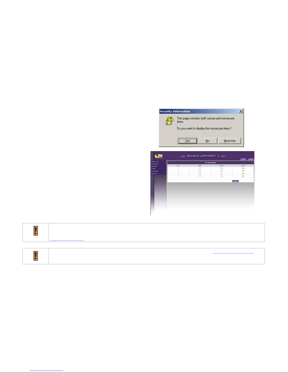
6. After successful login you will see the controller web
interface. Now you are enabled to perform your
configuration.
For the first web browser, you will be directed to Quick Setup
page. Others will be directed to Status Monitor Page.
After the procedure as above, If you can’t access the MPES-4 with FreePP Starter, please check gateway IP address
from Ethernet connection status of your computer and type it in the web browser’s address bar directly. (e.g.
https://172.17.12.1).
You can remotely login by typing WAN IP address in the web browser’s address bar. (e.g. https://60.244.104.185 ).
Page 19
19
Chapter 5: Configuring the MPES-4 via Web Interface
Overview
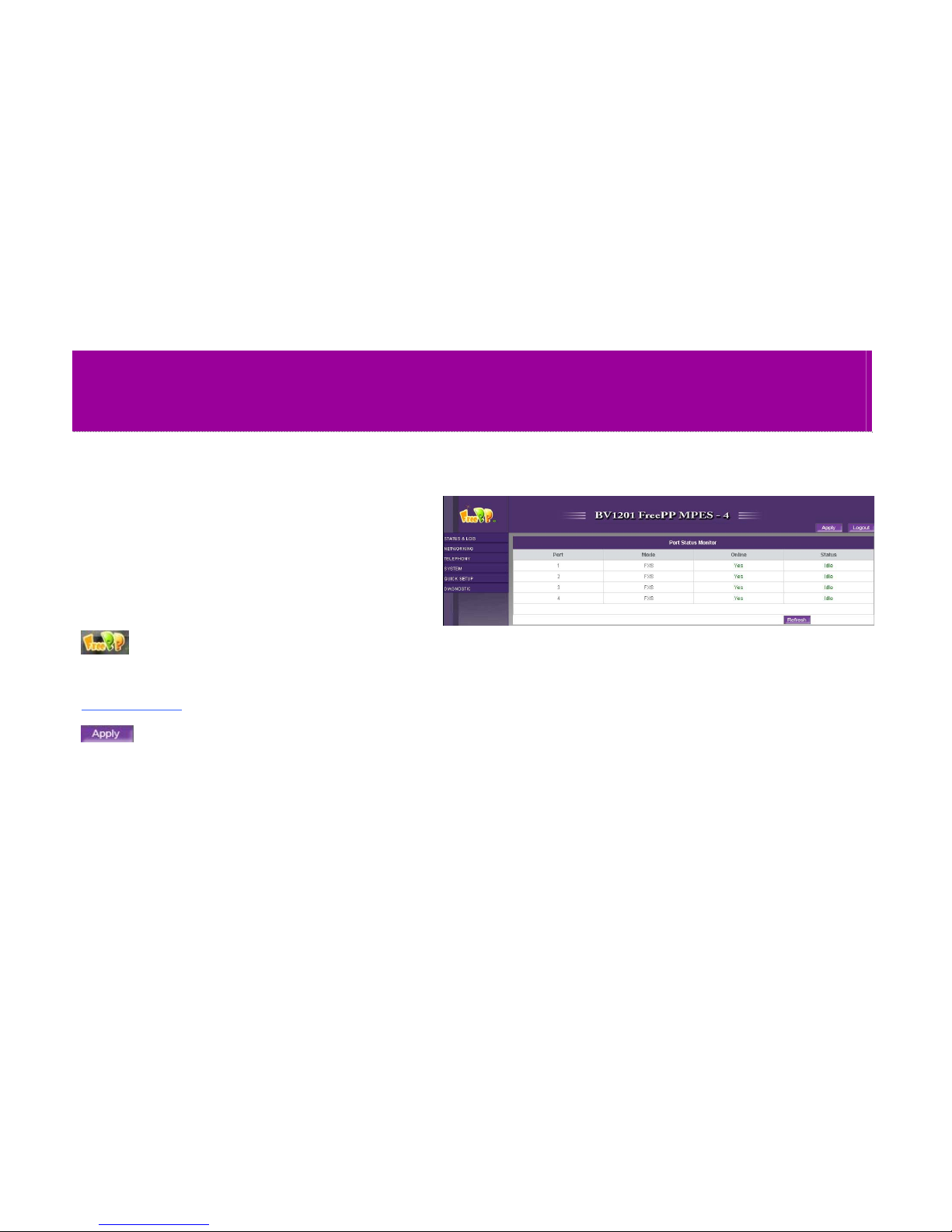
The main web management menu is displayed as follows
after successful login. From this page all essential
configuration pages are accessed.
The web management menu has the following structure.
The FreePP logo provides quick connection to
www.freepp.com when you click on it.
This button is always blinking after Save, an alert window
will always pop up when you click on Apply button, to
double check whether you want to apply all the changes
and reboot or not.
Page 20
20
You will logout and return to Login page after clicking on
Logout button.
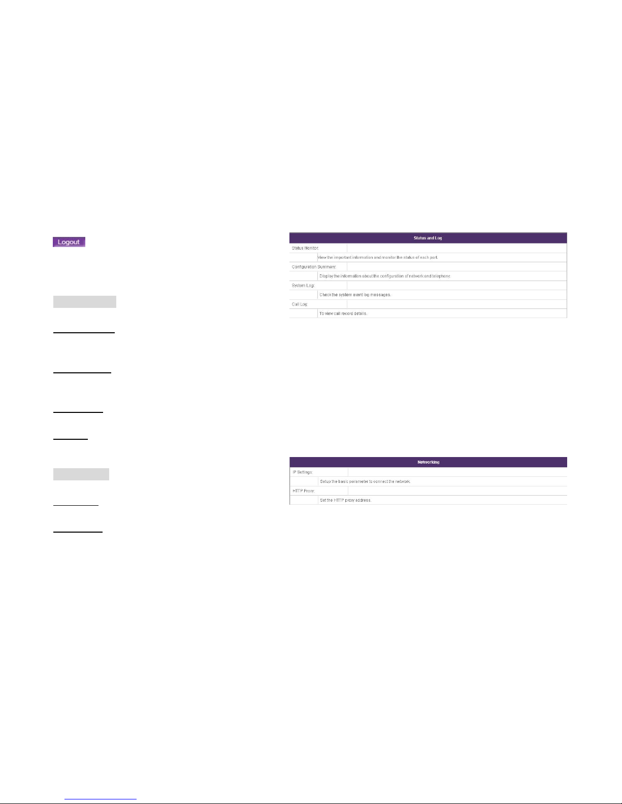
Status & Log
Status Monitor
View the important information and monitor the status of
each port.
Configuration
Display the information about the configuration of network
and telephony.
System Log
Check the system event log messages.
Call Log
To view the call record details.
Networking
IP Settings
Setup the basic parameter to connect the network.
HTTP proxy
Set the HTTP proxy address
Page 21
21
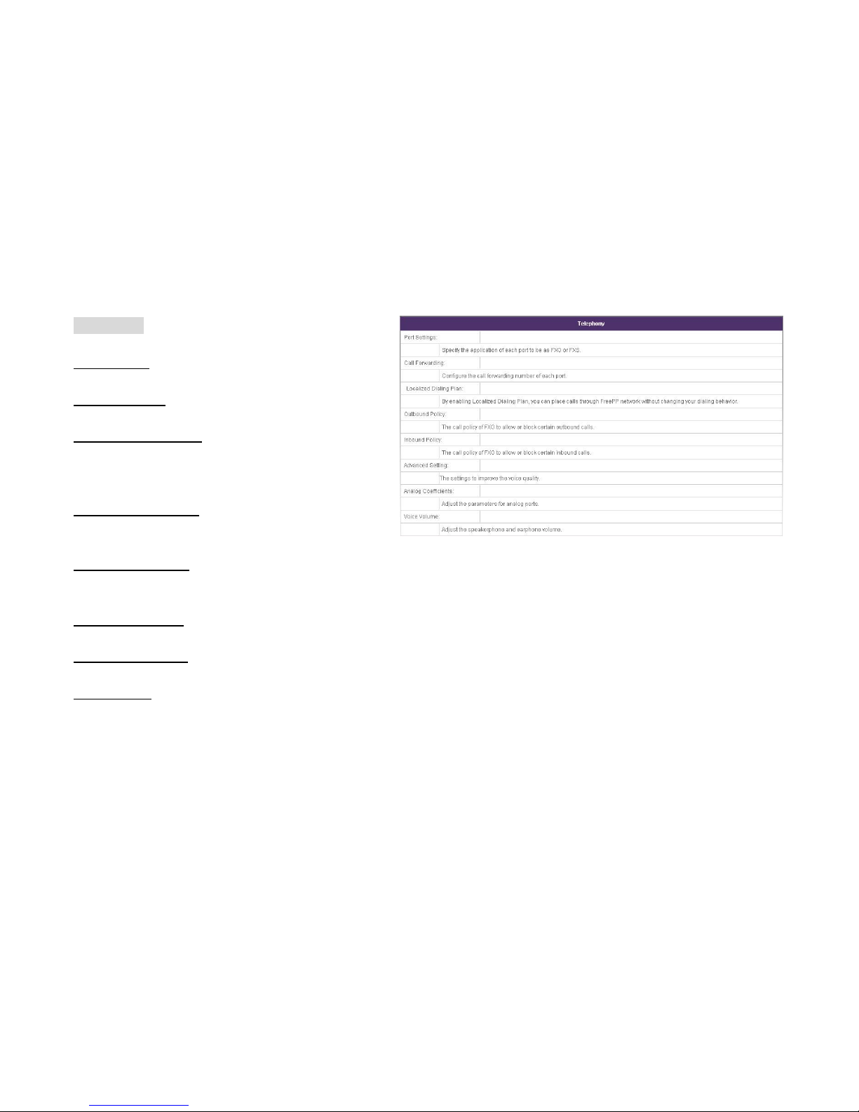
Telephony
Port Settings
Specify the application of each port to be as FXO or FXS
Call Forwarding
Configure the call forwarding number of each port.
Localized Dialing plan
By enabling Localized Dial Plan, you can place calls
through FreePP network without changing your dialing
behavior.
FXO Outbound policy
The call policy of FXO to allow or block certain outbound
calls.
FXO Inbound Policy
The call policy of FXO to allow or block certain inbound
calls.
Advanced Settings
The settings to improve the voice quality.
Analog Coefficients
Adjust the parameters for analog ports.
Voice Volume
Adjust the speakerphone and earphone’s volume.
Page 22
22
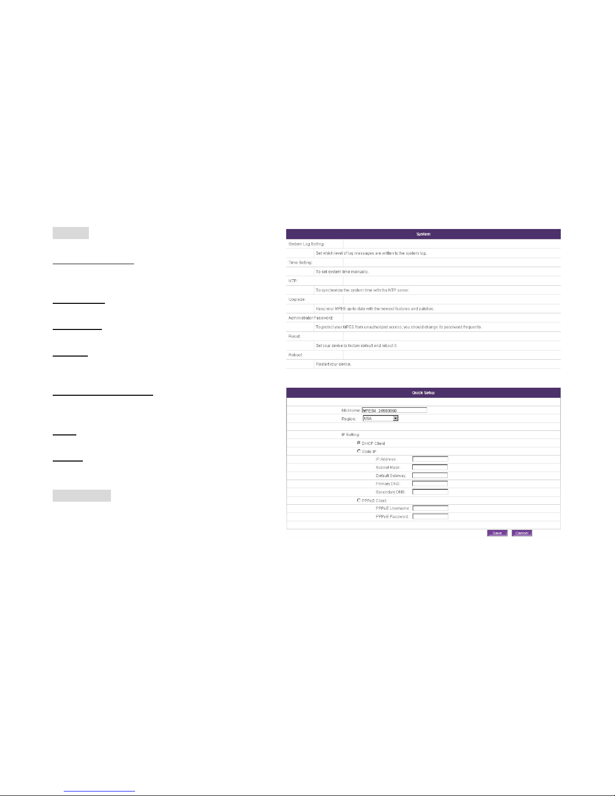
System
System Log Setting
Set which level of log messages are written to the system
log.
Time Setting
To set system time manually.
NTP Setting
To synchronize the system time with the NTP server.
Upgrade
To keep your MPES-4 up-to-date with the newest features
and patches.
Administrator password
To protect your MPES-4 from unauthorized access, you
should change its password frequently.
Reset
Set your device to factory default and reboot it.
Reboot
Restart your device.
Quick setup
When you log in MPES-4 with factory default setting and it
can not connect to the server. You can set up the network
environment in this page.
Page 23
23
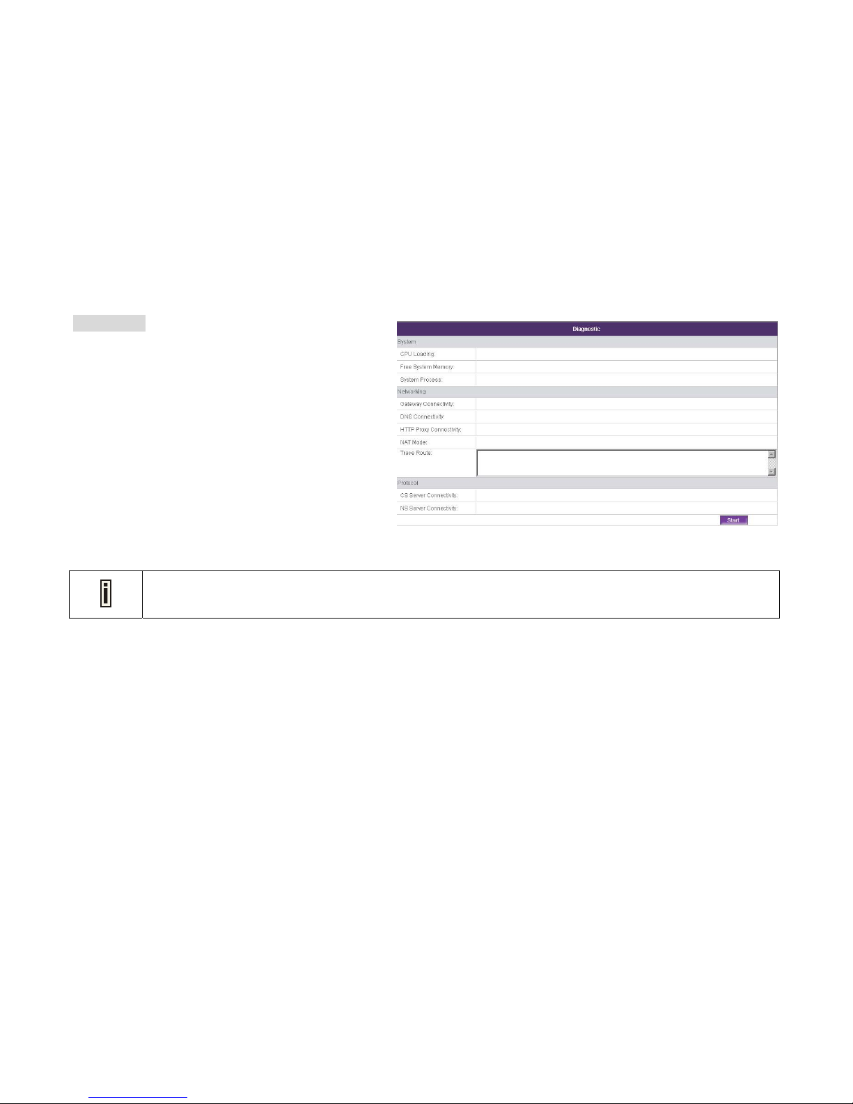
Diagnostic
To check the MPES-4 current information, including
running and status.
You will return to Login page if you do no action on any page within 3 minutes.
Page 24
24
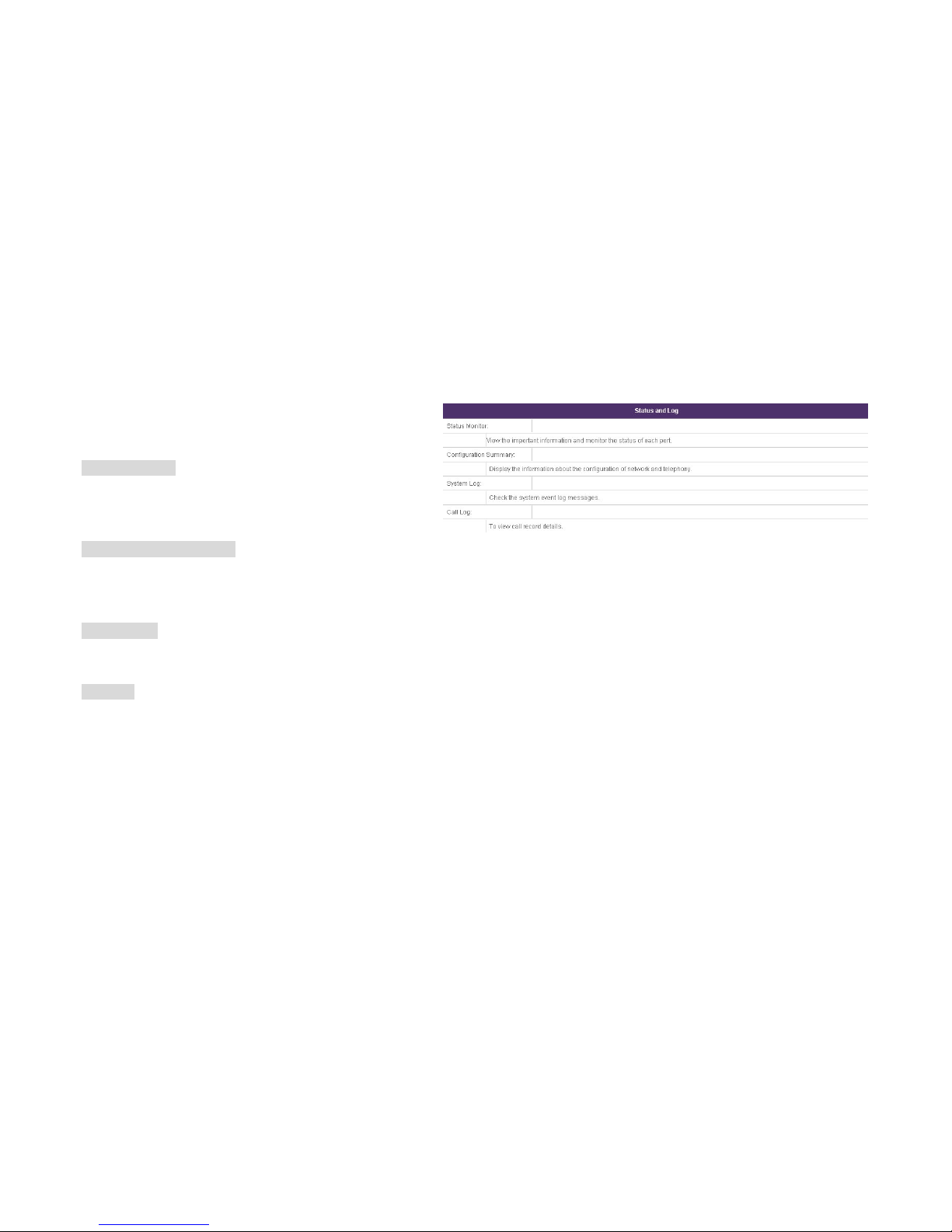
Status & Log
This page shows each sub menu’s definition under Status
and Log.
Status Monitor
To view the important information and monitor the status of
each port.
Configuration Summary
To display the information about the configuration of
network and telephony.
System Log
To check the system event log messages.
Call Log
To view call record details.
Page 25
25
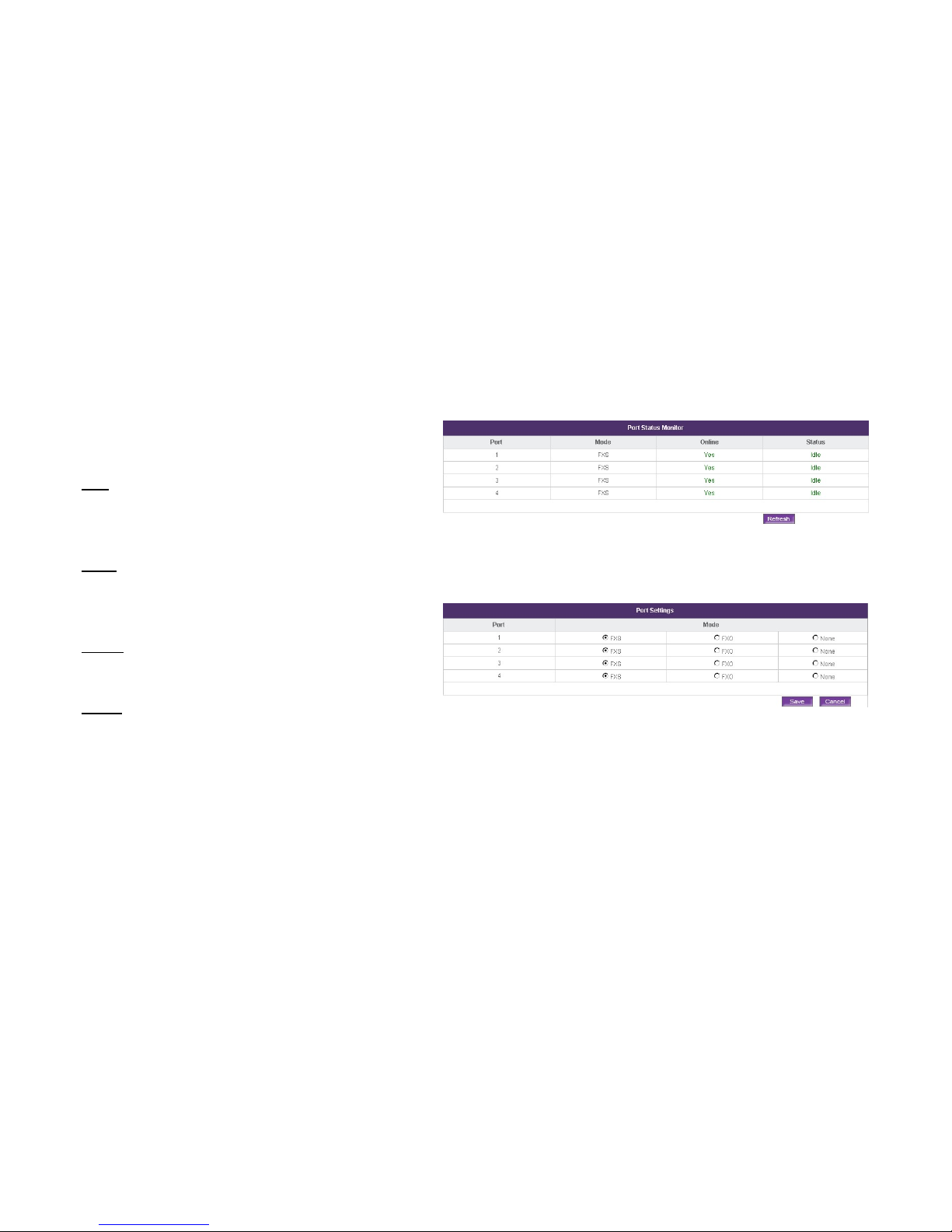
Status & Log | Status Monitor
The Status Monitor page shows important information for
the MPES-4 as on the right.
Port
Display the telephone port number, which with range from
1 to 4 since the MPES-4 has 4 FXO ports and 4 FXS ports.
Mode
Display the current port mode, such as FXO, FXS and
NONE.
Online
Display whether FXO or FXS is online or not.
Status
Display whether FXO or FXS is busy or idle.
Click Refresh button to refresh the current information
manually. In fact the MPES-4 will refresh every 10 seconds
automatically.
You will be directed to Port Settings page while clicking
on FXO, FXS or NONE.
Page 26
26
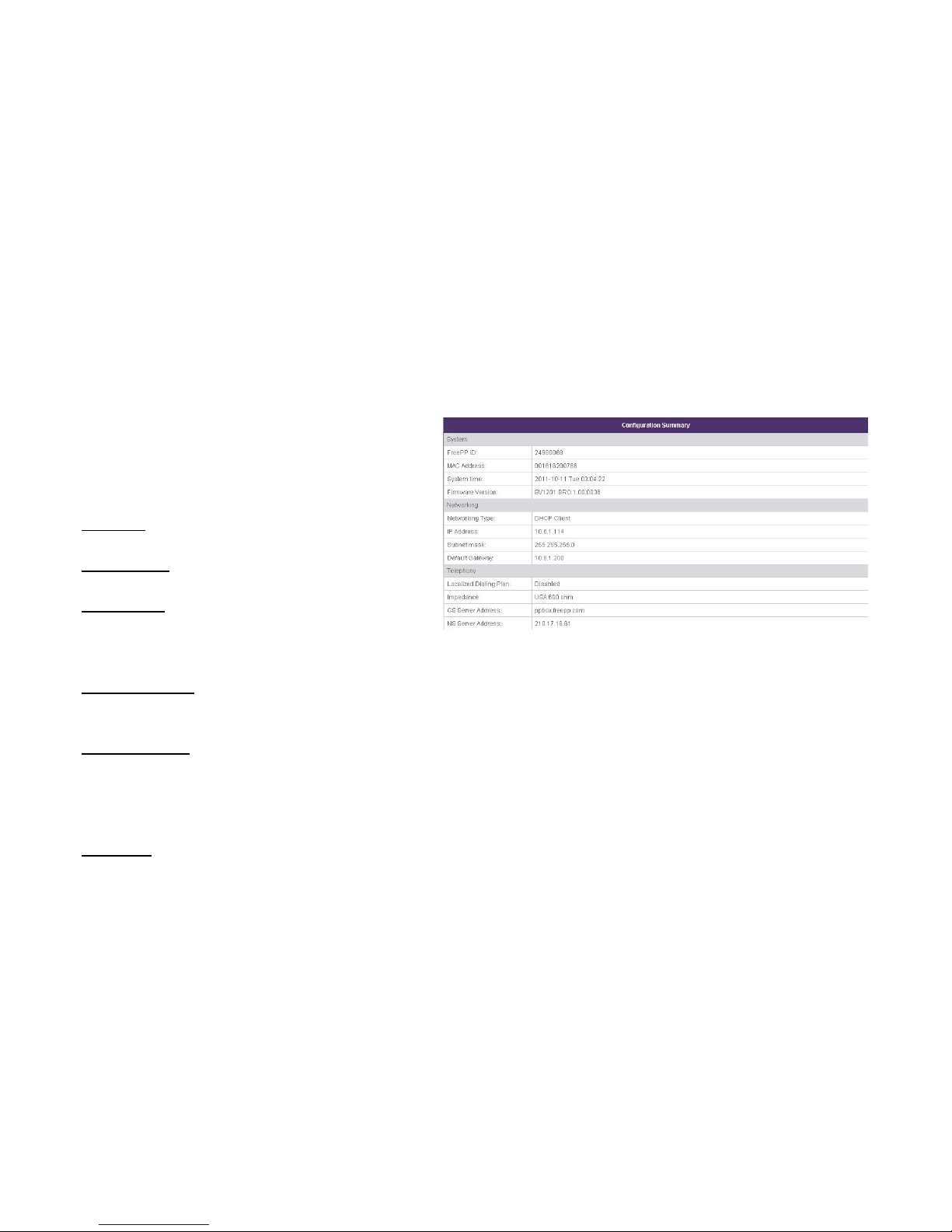
Status & Log | Configuration
This configuration page shows configuration summary for
the MPES-4, including System, Networking and
Telephony, and provide quick access to relative
configuration pages.
FreePP ID
Identification number of the MPES-4.
MAC Address
To show the MAC address of the MPES-4.
System Time
To show the current time of the MPES-4. You will be
directed to Time Setting page while clicking on System
Time.
Firmware Version
To show the current firmware version of the MPES-4.
Networking Type
To indicate which Networking type is used for the MPES-4,
such as DHCP, Static IP or PPPoE Client. You will be
directed to IP Setting page while clicking on Networking
Type.
IP Address
To show the IP address of the MPES-4. You will be
Page 27

27
directed to IP Settings page while clicking on IP Address.
Subnet mask
To show the Subnet mask of the MPES-4. You will be
directed to IP Settings page while clicking on Subnet
mask.
Default Gateway
To show the gateway address of the MPES-4. You will be
directed to IP Settings page while clicking on Default
Gateway.
Localized Dialing Plan
To indicate whether localized dialing plan is enabled or
disabled. You will be directed to Localized Dialing Plan
page while clicking on Localized Dialing Plan.
Impedance
To show the current Impedance value. You will be directed
to Advanced Setting page while clicking on Impedance.
CS Server Address
To show the current CS Server Address of the MPES-4.
You will be directed to Advanced Setting page while
clicking on CS Server Address.
NS Server Address
To show the current NS Server Address of the MPES-4.
You will be directed to Advanced Setting page while
clicking on NS Server Address.
Page 28
28
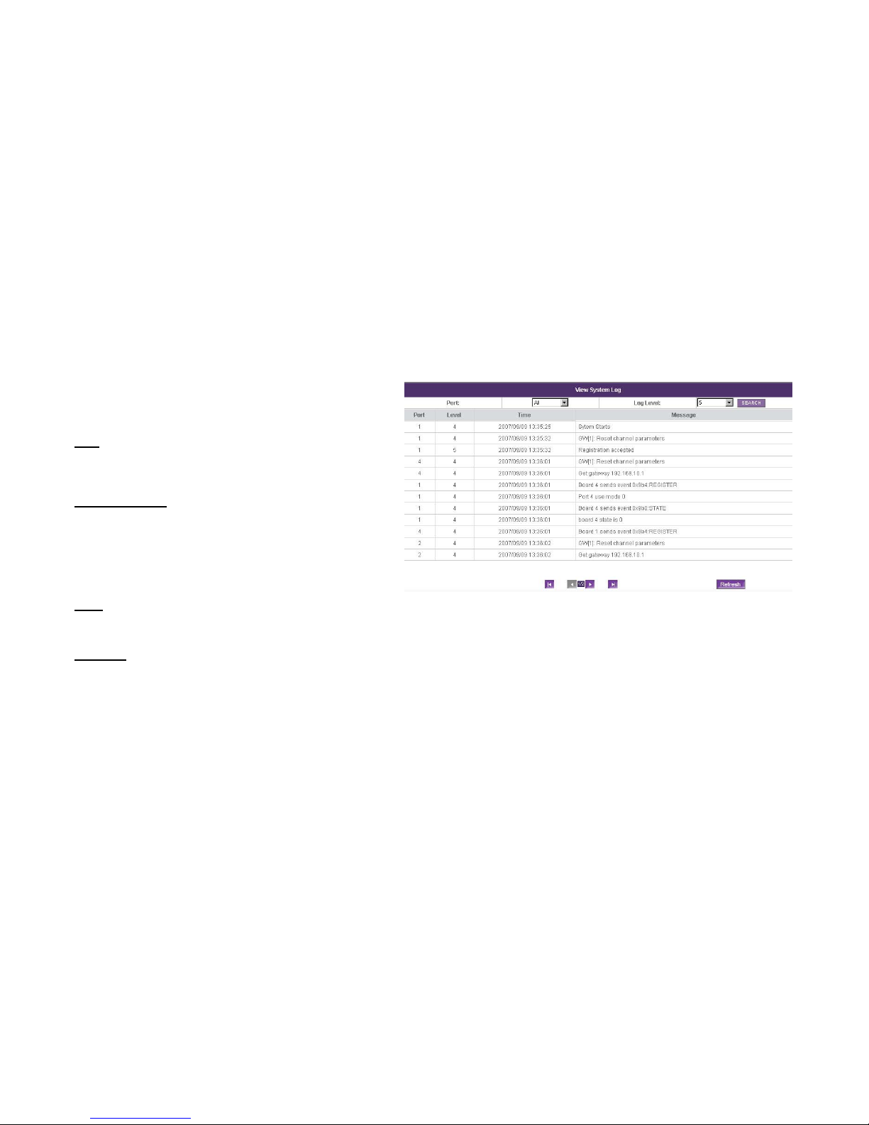
Status & Log | System Log
You can check the MPES-4’ system log information in this
page.
Port
Specify the port number, which is from 1 to 4, or All.
Default port value is All.
Log Level/Level
Specify the log message level from 1 to 5. One (1) means
the system will display the fewest amount of message;
otherwise, five (5) means the system will display the most
amount of message.
Time
Specify the time when system log is recorded.
Message
Specify the system log event.
Page 29
29
1. Please enable log status in System Log Setting page.
The Apply button will blink after Save. Please click Apply
button to apply all the changes if necessary. All the
changes will be applied after reboot.
2. Select the Port number and Log level as your need,
then click SEARCH button to select the system log
message.
3. Click Refresh button to refresh the system log manually.
In fact the MPES-4 will refresh the system log message
every 60 seconds automatically.
4. Turn pages
Click < button to go backward and > button to go forward.
Page 30
30
Status & Log | Call Log
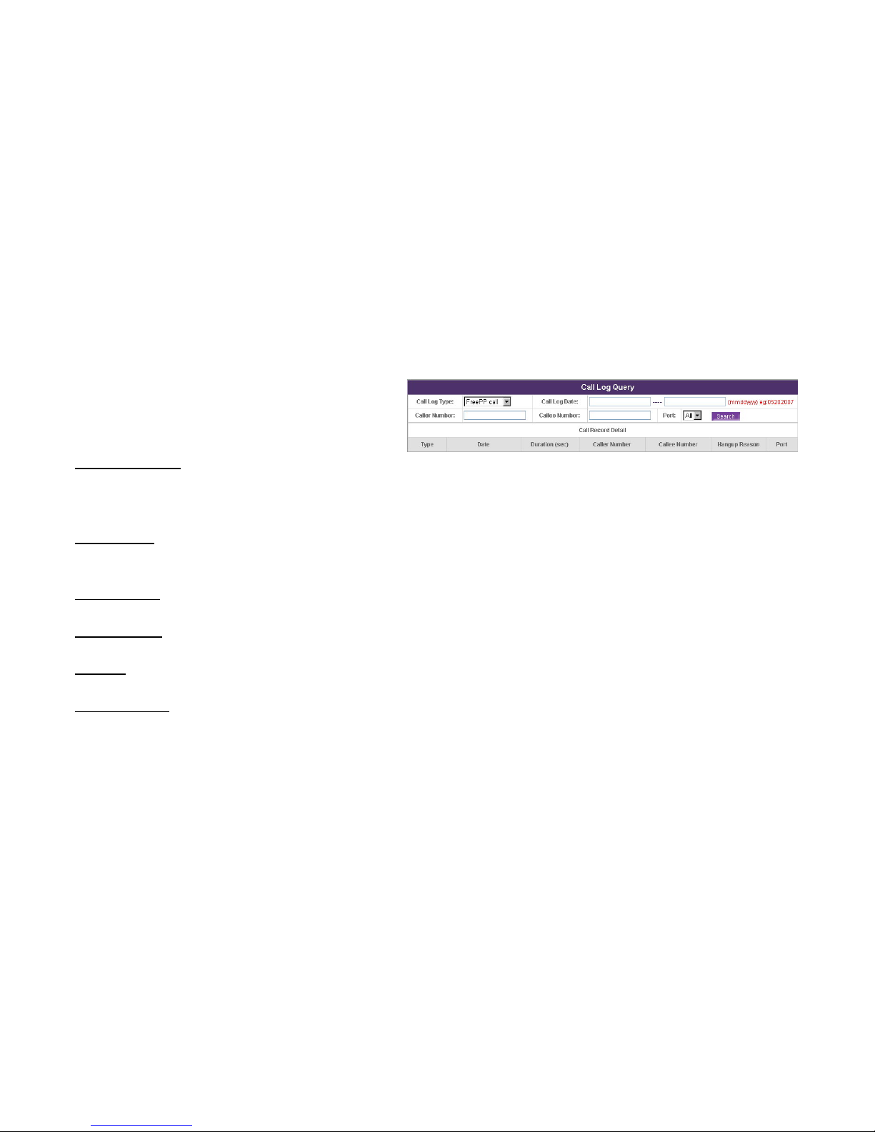
You can check MPES-4’ call record details in this page,
which contain information related to original call number
and destination number.
Call log type/Type
Specify the call log type such as FreePP call, FXO
outbound, FXO inbound, and All Type. Default type is
FreePP call.
Call Log Date
Specify the date when call log is recorded, format of which
is mmddyyyy. eg, 0520007 means May 20th 2007.
Caller Number
Show the original caller’s number.
Callee Number
Show the destination number.
Duration
Specify the period lasts from the call answered to hang up.
Hangup Reason
Specify the reason why the call is hang up.
Click < button to go backward and > button to go forward.
Click SEARCH button to select the call log message.
Page 31

31
Networking
You can establish your internet connection environment by
IP Settings or setting HTTP Proxy.
IP Settings
Setup the basic parameter to connect the network.
HTTP Proxy
Set the HTTP proxy address.
Page 32
32
Networking | IP Settings
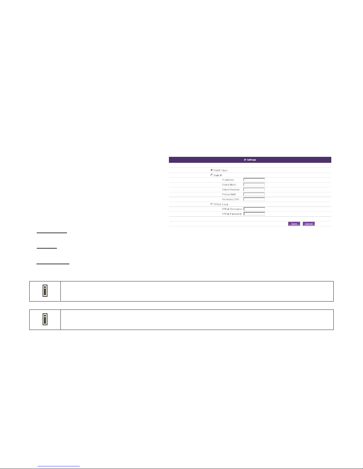
You can establish your internet connection environment by
IP Setting. You can choose one of the following types of
network connection based on your network environment.
IP Settings
To setup the basic parameter to connect the network.
There are three ways to implement the IP Settings.
a. DHCP Client
Obtain an IP address automatically.
b. Static IP
Use the specified static IP address.
c. PPPoE Client
Broadband connection with a username and password.
The MPES-4 is set as DHCP client by default.
If you are not familiar with these settings, please consult the network administrator.
Page 33
33
Networking | IP Settings | DHCP Client
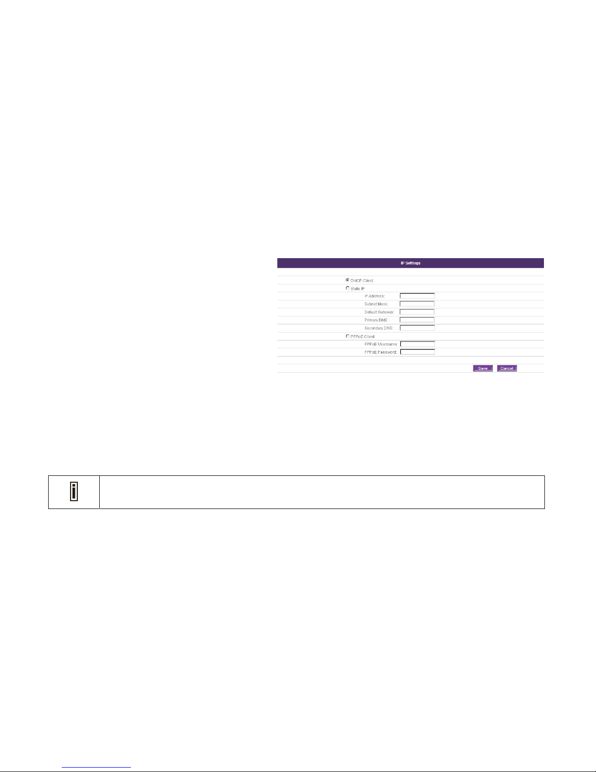
DHCP Client is the default option. If you are not very sure
about the IP setting for the MPES-4, choose DHCP Client
mode. The MPES-4 will use an assigned IP address from
your network router or gateway. Otherwise, MPES-4 will
intelligently try all possible IP settings in the cache memory
to connect your MPES-4 to the network.
DHCP
Dynamic Host Configuration Protocol.
1. Select DHCP Client.
2. Click Save button to save the entered values.
Click Cancel button to restore all previous values.
3. The Apply button will blink after Save. Please click
Apply button to apply all the changes if necessary. All
the changes will be applied after reboot.
The MPES-4 has a DHCP server embedded. That means by enabling the router mode, the MPES-4 will assign a
dynamic IP to the device connected to the Configuration port of your MPES-4.
Page 34
34
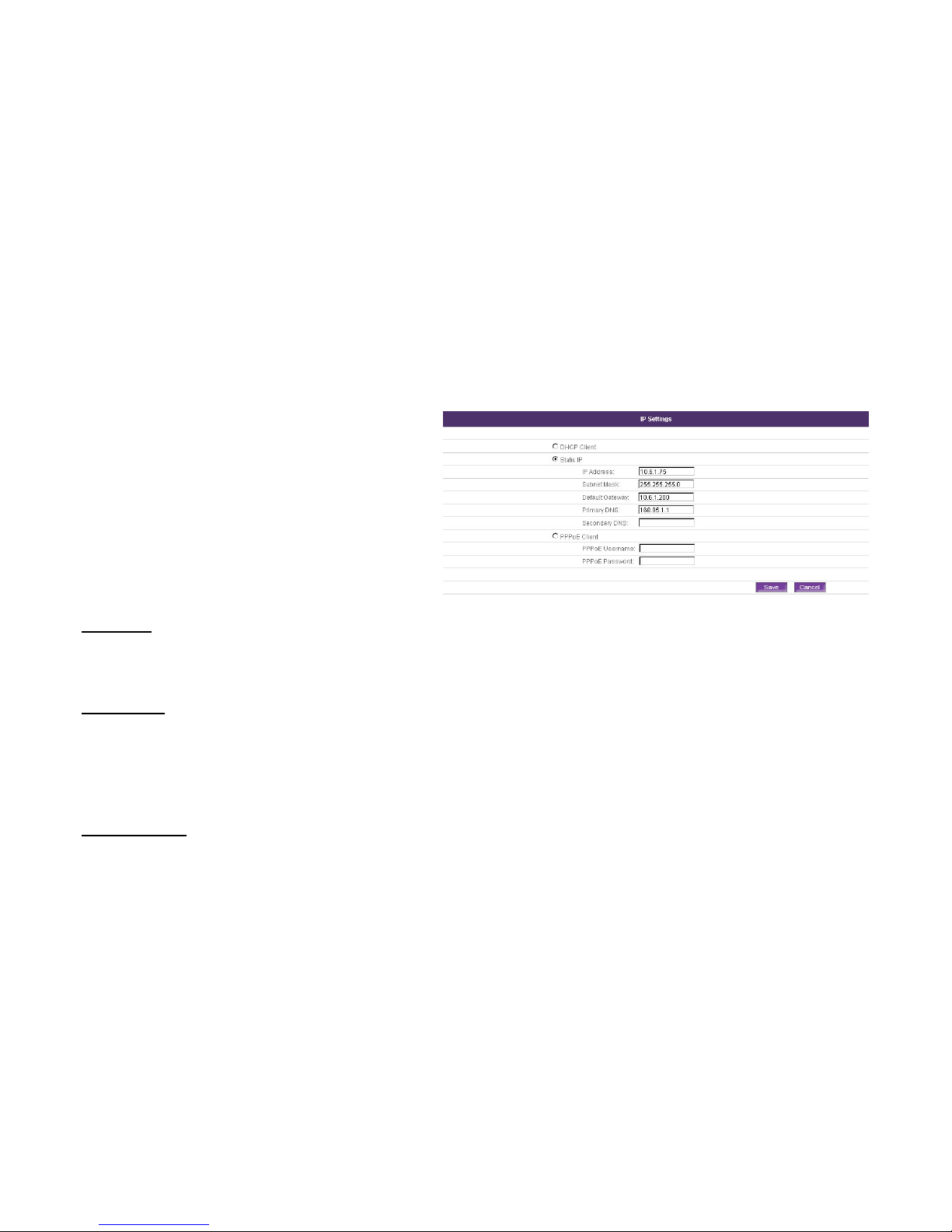
Networking | IP Settings | Static IP
You can use the specified static IP address to configure
your MPES-4.
If your MPES-4 has been allocated a specified static IP
address, please fill out the necessary IP settings here. If
you are not familiar with these settings, please consult the
network administrator.
Static IP
Use the specified static IP address.
IP Address
Specified IP address for your MPES-4, in digits and dots
notation ([0-255]. [0-255]. [0-255]. [0-255], e.g.
192.168.121.70).
Subnet Mask
Specified Subnet Mask for your MPES-4 in digits and dots
notation ([0-255]. [0-255]. [0-255]. [0-255], e.g.
255.255.252.0). These numbers are a binary mask of the
IP address, which defines IP address order and the
number of IP addresses in the subnet.
Default Gateway
Specified the interface gateway in digits and dots notation
([0-255]. [0-255]. [0-255]. [0-255], e.g. 192.168.123.1).
Page 35
35
Primary DNS
Specified the DNS server’s IP address in digits and dots
notation ([0-255]. [0-255]. [0-255]. [0-255], e.g.
202.96.209.5).
Secondary DNS
Specified the secondary DNS server’s IP address in digits
and dots notation ([0-255]. [0-255]. [0-255]. [0-255], e.g.
202.96.209.13). Or you can leave it blank.
1. Select Static IP.
2. Fill out IP Address, Subnet Mask, Default Gateway,
DNS settings.
3. Click Save button to save the entered values. MPES-4
will check if the entered values are valid automatically
before saving them.
Click Cancel button to restore all previous values.
4. The Apply button will blink after Save. Please click
Apply button to apply all the changes if necessary. All
the changes will be applied after reboot.
1. The Secondary DNS can be left blank while Primary DNS can not be blank.
2. The Secondary DNS can not be with the same value as Primary DNS.
Page 36
36
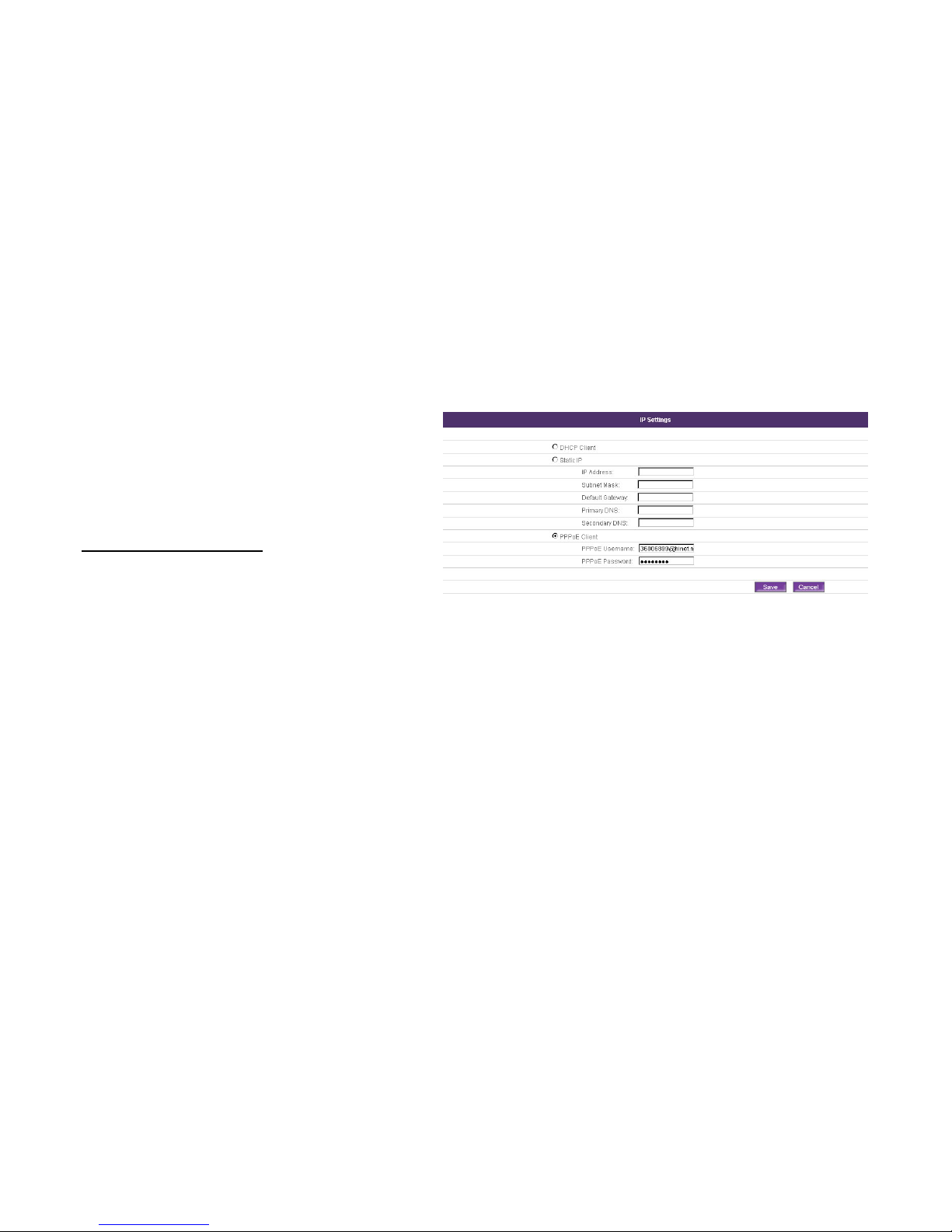
Networking | IP Settings | PPPoE Client
PPPoE Stands for Point-to-Point Protocol over Ethernet.
PPPoE is a specification for connecting the users on an
Ethernet to the Internet through a common broadband
medium, such as a single DSL line, wireless device or
cable modem.
PPPoE Username/Password
Direct cable connection needs username and password.
1. Fill out your PPPoE Username and password.
2. Click Save button to save the entered values.
Click Cancel button to restore all previous values.
3. The Apply button will blink after Save. Please click
Apply button to apply all the changes if necessary. All
the changes will be applied after reboot.
Page 37

37
Networking | HTTP proxy
You can establish your internet connection environment by
setting HTTP Proxy.
HTTP Proxy Server
It sits between a client application, such as a Web
browser, and a real server. It intercepts all the requests to
the real server to see if it can fulfill the requests
themselves. If not, it forwards the requests to the real
server.
Proxy Address
Specify the domain address to communicate with Internet,
in digits and dots notation. ([0-255]. [0-255]. [0-255].
[0-255])
Port
Specify the network port used to communicate with the
Authentication server, with value between 1 and 65535.
1. Choose Enabled/Disabled the Http proxy server
setting. Default HTTP Proxy service is Disabled.
2. Fill out the IP settings of the Proxy Server here.
3. Click Save button to save the entered values.
Click Cancel button to restore all previous values.
4. The Apply button will blink after Save. Please click
Apply button to apply all the changes if necessary. All
the changes will be applied after reboot.
Page 38
38
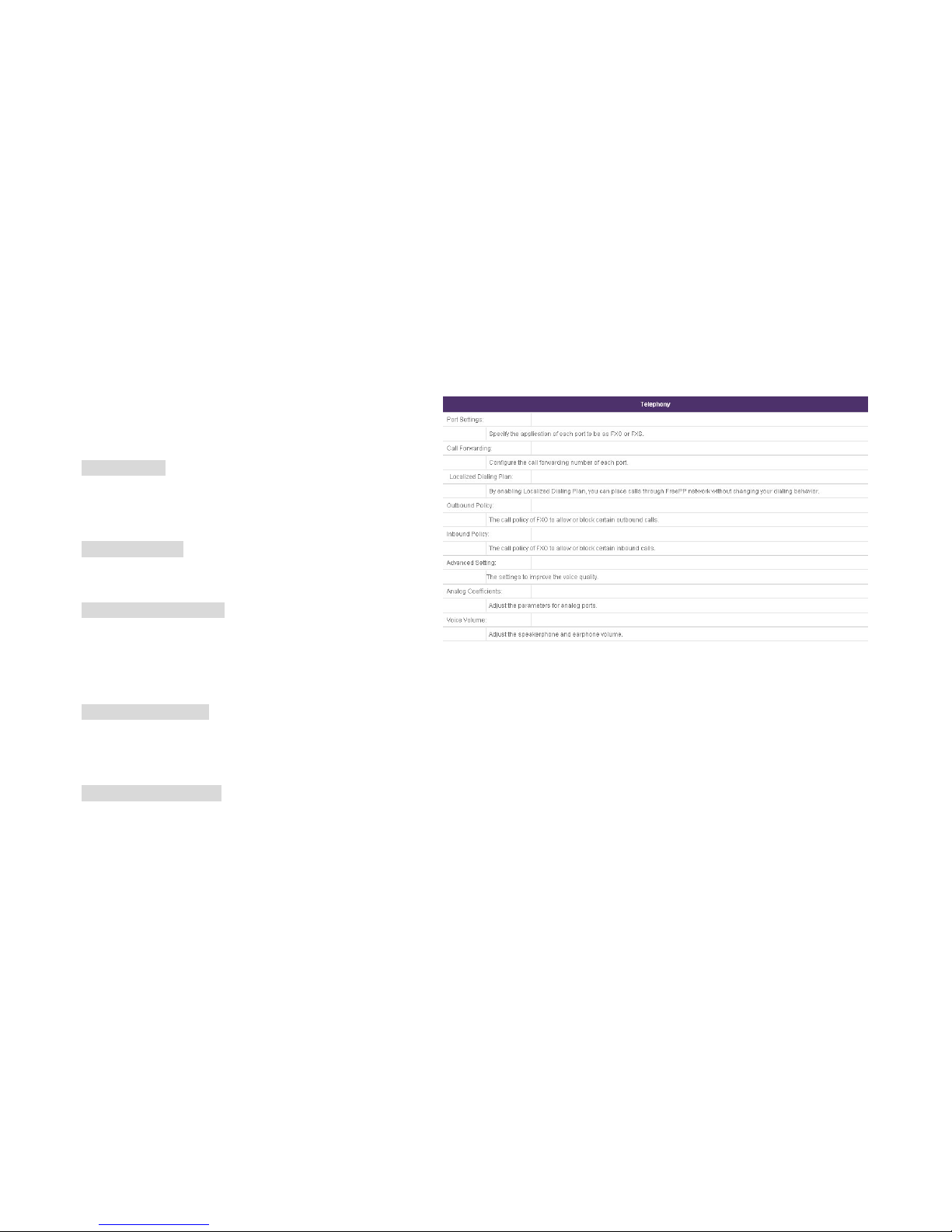
Telephony
This page is to show Telephony’s sub-menu and provide
quick access to each sub-menu by clicking on them.
Port Settings
Select the application of each port, and define it to act as a
FXO port or a FXS port.
Call Forwarding
Configure the call forwarding number of each port.
Localized Dialing Plan
By enabling Localized Dialing Plan, you can place calls
through FreePP network without changing your dialing
behavior.
FXO Inbound policy
The call policy of FXO to allow or block certain landline
calls.
FXO Outbound Policy
The call policy of FXO to allow or block certain FreePP
outbound calls.
Page 39

39
Advanced Setting
Specify the settings to improve the voice quality.
Analog Coefficients
Adjust the parameters for analog ports.
Voice Volume
Adjust the speakerphone and earphone volume.
Page 40
40
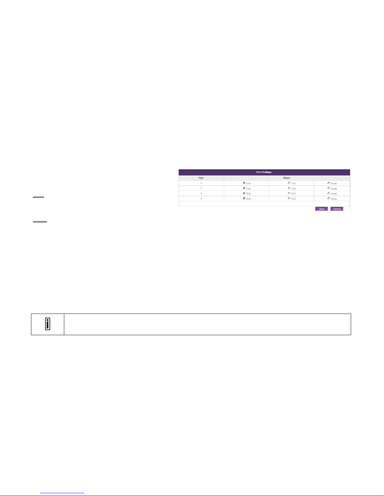
Telephony | Port Setting
You can change the port settings by the connection to
PBX.
Port
Display the telephone port number.
Mode
Specify the current telephone port mode, such as FXO,
FXS and None.
1. Select the port mode as your need.
2. Click Save button to save the entered values.
Click Cancel button to restore all previous values.
3. The Apply button will blink after Save. Please click
Apply button to apply all the changes if necessary. All
the changes will be applied after reboot.
Note that all ports can be only assigned to FXS or FXO mode respectively.
Page 41
41
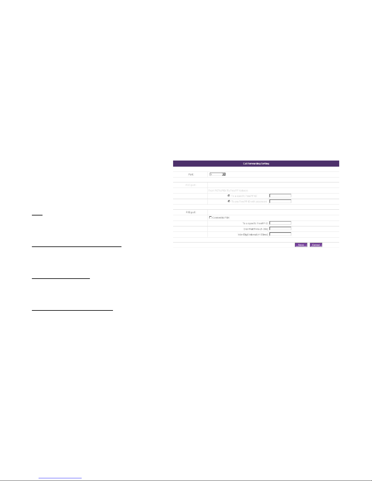
Telephony | Call forwarding Setting
This page allows you to do the call forwarding
configuration, based on the port and mode you selected
on Port Setting page. The port mode selected is enabled
to be configured, while the other port mode unselected is
disabled.
Port
Display the telephone port number. The Web page will go
backward to Port Settings page when you click on Port.
From PSTN/PBX to FreePP Network
Specify the action to redirect all the incoming calls from
PSTN or PBX to FreePP Network.
To a specific FreePP ID
Specify the action to redirect all the incoming calls from
PSTN to a specific FreePP ID.
To any FreePP ID with password
Specify the action to redirect all the incoming calls from
PSTN to any FreePP ID with or without password. Default
setting is without password.
Page 42

42
Password
The password should be a 6 to 30-digits number or blank.
Blank means no password.
Connect to PBX
To establish connection from FXS to PBX.
Dial Wait Time
Specify the wait time to send the first dialed number. The
time range is between 1 and 30 seconds.
Inter-Digit Interval
Specify the time interval to send every two dialed
numbers. The interval range is between 100 and 999
milliseconds.
Page 43

43
* FXO ports are connected to PBX:
There are two modes for FXO call forwarding:
1. Click To any FreePP ID with password radio button
and enter the password, or you may leave it blank. To
any FreePP ID without password is the default setting
for FXO mode.
2. Click To a specific FreePP ID button and enter the
FreePP ID.
Click Save button to save the entered values.
Click Cancel button to restore all previous values.
The Apply button will blink after Save. Please click
Apply button to apply all the changes if necessary. All
the changes will be applied after reboot.
Page 44
44
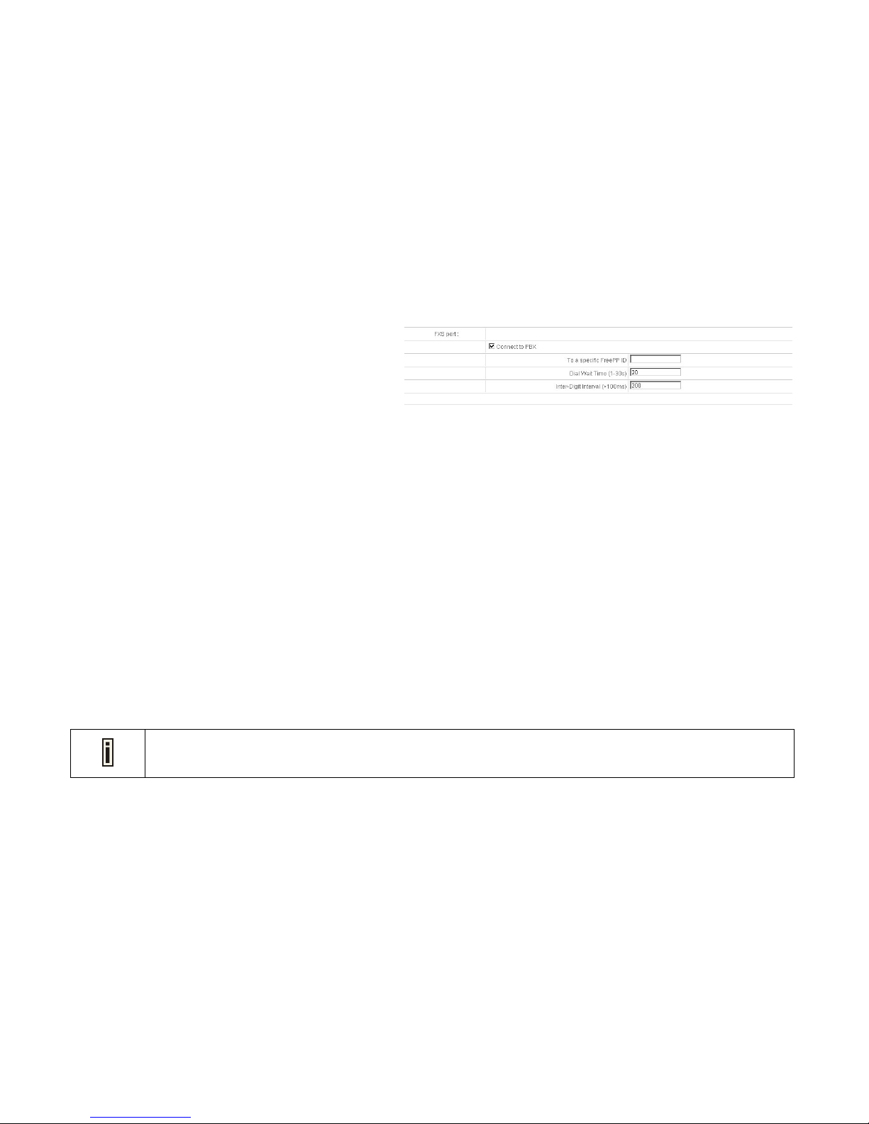
* FXS ports are connected to PBX:
1. Check the checkbox of Connect to PBX.
2. The function, To a specific FreePP ID is like Hotline,
that is used when you pick up the internal extension of
PBX and switch to MPES-4, MPES-4 will automatically
dial to the specific FreePP ID you entered.
Please note that if specific FreePP ID is set, you cannot
make any calls, except to the specific FreePP ID.
3. Set the dial wait time and Inter-Digit Interval. These two
values are compulsive ones so they can not be blank.
4. Click Save button to save the entered values.
Click Cancel button to restore all previous values.
5. The Apply button will blink after Save. Please click
Apply button to apply all the changes if necessary. All
the changes will be applied after reboot.
1. On-Net Call forwarding function is enabled all the time.
2. Only on-net configuration is allowed for FXO port on this page.
Page 45
45
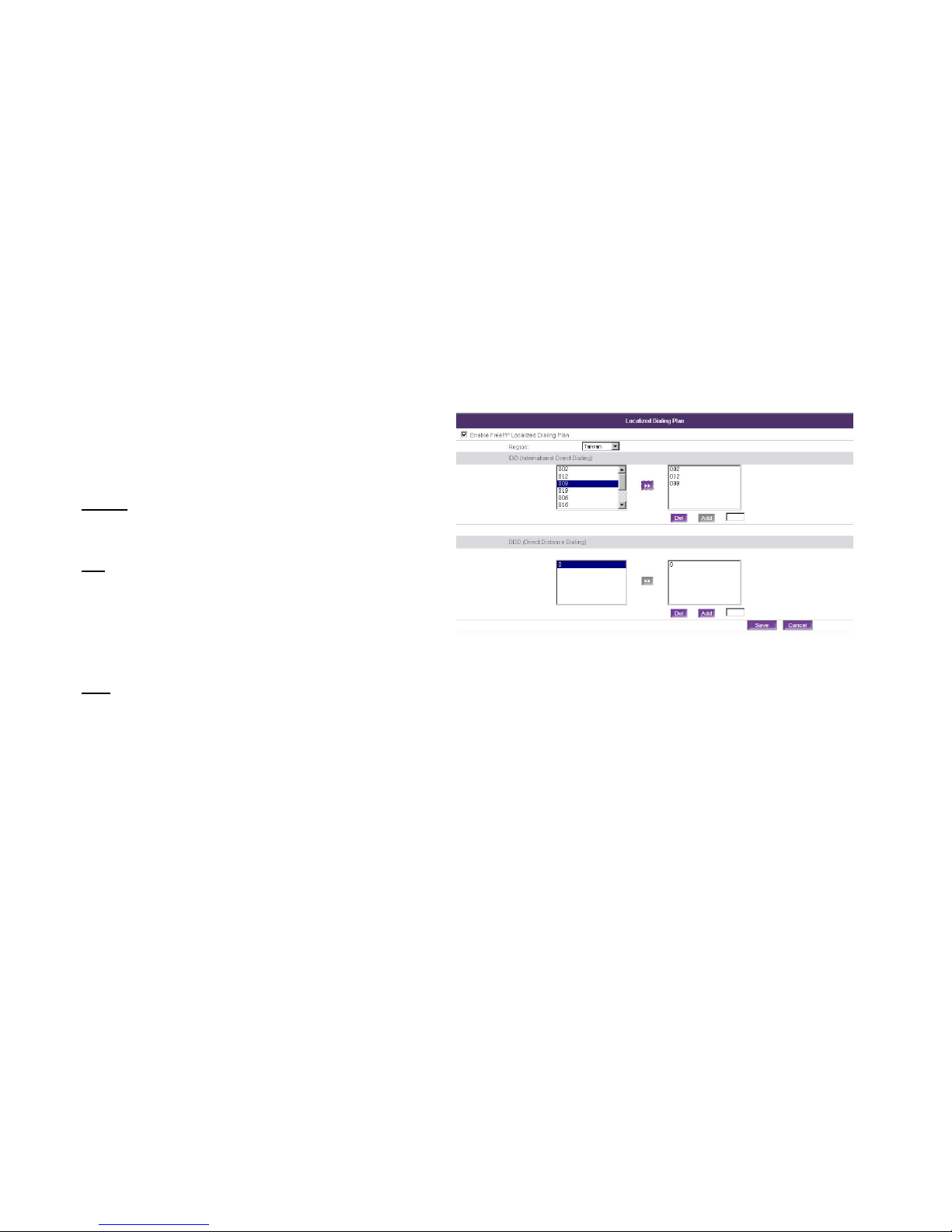
Telephony | Localized Dialing Plan
By enabling Localized Dialing Plan, you can place calls
through FreePP network without changing your dialing
behavior.
Region
Specify the region where you are located. Default is USA.
IDD
International Direct Dialing. International Prefix of your
country code. The left table includes the standard IDD
value, while the right table includes the true value IDD you
edited.
DDD
Direct Distance Dialing. Trunk Prefix of your area code.
The left table includes the standard DDD value, while the
right table includes the true value DDD you edited.
1. Check Enable FreePP Localized Dial Plan checkbox
to subscribe Localized Dial Plan service.
2. Select the region where you are located from the
dropdown list.
3. Add IDD/DDD number. You have to choices to add
Page 46
46
prefix codes as follows:
a、Select the prefix codes from the standard IDD/DDD
tables on the left, then click >> Button to add the prefix
codes to the true value tables on the right.
b、Input the prefix codes in the textboxes below the true
value tables on the right, then click ADD button to add
the them to the real value tables.
4. Delete IDD/DDD number. Select prefix codes on the
right real value tables, click Del button to remove them
from the true value tables.
5. Click Save button to save the entered values.
Click Cancel button to restore all previous values.
6. The Apply button will blink after Save. Please click
Apply button to apply all the changes if necessary. All
the changes will be applied after reboot.
1. Standard IDD t able on the lef t can not be modified or blank, while standard DDD table can not be modified but can
be blank.
2. True IDD/DDD value tables on the left can be set blank.
Page 47
47
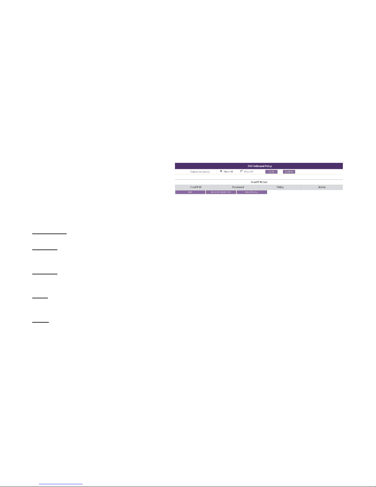
Telephony | FXO Outbound Policy
This page allows you to configure FXO outbound policy.
Default call policy
Specify the policy whether the MPES-4 will allow all or
block all FreePP calls to pass through FXO. Exception will
be listed in the FreePP ID list.
Default setting is Allow All.
FreePP ID list
Specify the exception policy of FreePP numbers.
FreePP ID
Specify the FreePP ID you want them to action differently
from the default ones.
Password
Specify the password for the FreePP ID. Only digits are
acceptable, the length is within 16.
Policy
Specify the policy whether the FreePP call through FXO is
allowed or blocked.
Action
There are four kinds of actions.
Page 48

48
1. Edit
Specify the action to change Policy and Password.
2. ADD
Specify the action to add the FreePP ID, Password and
Policy.
3. DELETE SELECTED
Specify the action to delete the FreePP ID selected
from FreePP ID list. An alert window will appear to
make sure while this button is clicked.
4. DELETE ALL
Specify the action to delete all the FreePP ID from
FreePP ID list. An alert window will appear to make
sure while this button is clicked.
1. Select the policy is allow all or block all.
2. Edit the FreePP IDs, password (or leave it blank) and
call policy (allow or block) to the list.
3. Click Save button to save the entered values.
Click Cancel button to restore all previous values.
4. The Apply button will blink after Save. Please click
Apply button to apply all the changes if necessary. All
the changes will be applied after reboot.
Page 49
49
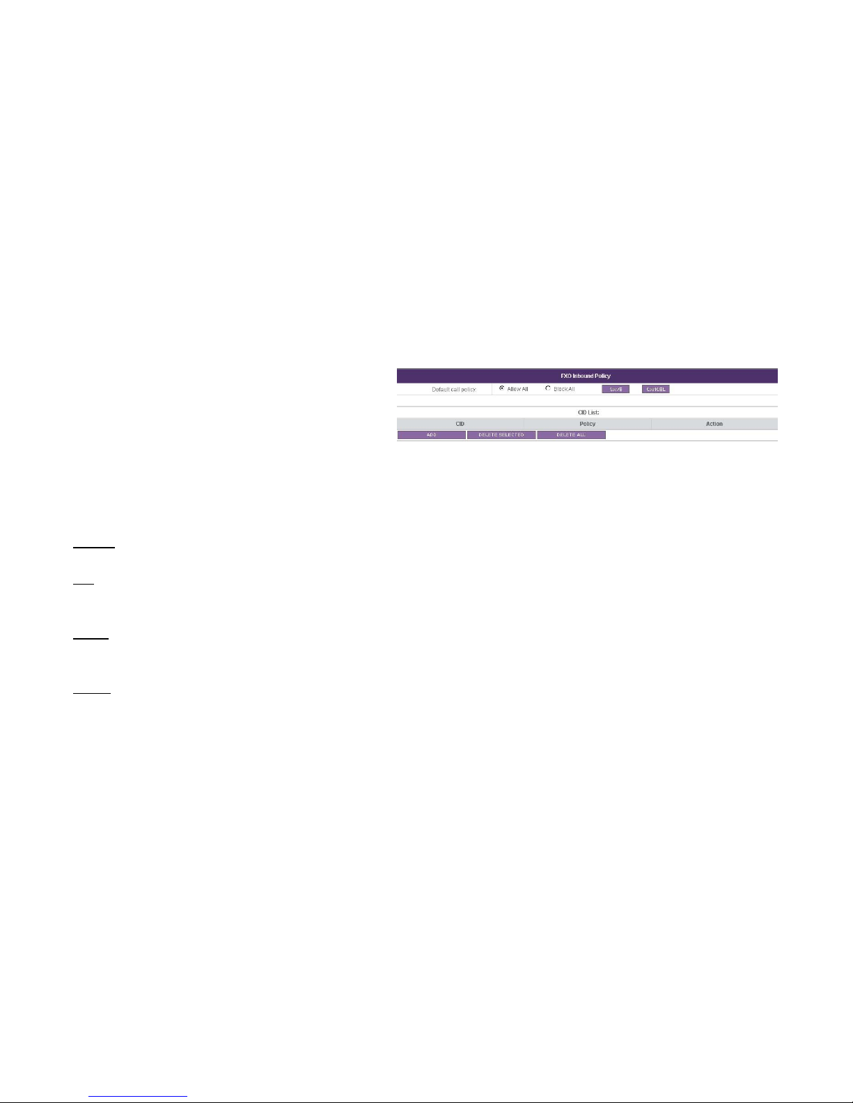
Telephony | FXO Inbound Policy
This page allows you to configure FXO inbound policy.
Default call policy
Specify the policy whether the MPES-4 will allow all or
block all landline number to pass through FXO. Exception
will be listed in the CID list.
Default setting is Allow All.
CID list
Specify the exception policy of landline number.
CID
Specify the landline number you want them to action
differently from the default ones.
Policy
Specify the policy whether the landline calls through FXO
is allowed or blocked.
Action
There are four kinds of actions.
Page 50

50
1. Edit
Specify the action to change Policy.
2. ADD
Specify the action to add the CID and policy.
3. DELETE SELECTED
Specify the action to delete the landline number
selected from CID list. An alert window will appear to
make sure while this button is clicked.
4. DELETE ALL
Specify the action to delete all the landline number
from CID list. An alert window will appear to make sure
while this button is clicked.
1. Select the policy is allow all or block all.
2. Edit the Caller IDs and call policy (allow or block) to the
list.
3. Click Save button to save the entered values.
Click Cancel button to restore all previous values.
4. The Apply button will blink after Save. Please click
Apply button to apply all the changes if necessary. All
the changes will be applied after reboot.
Page 51
51
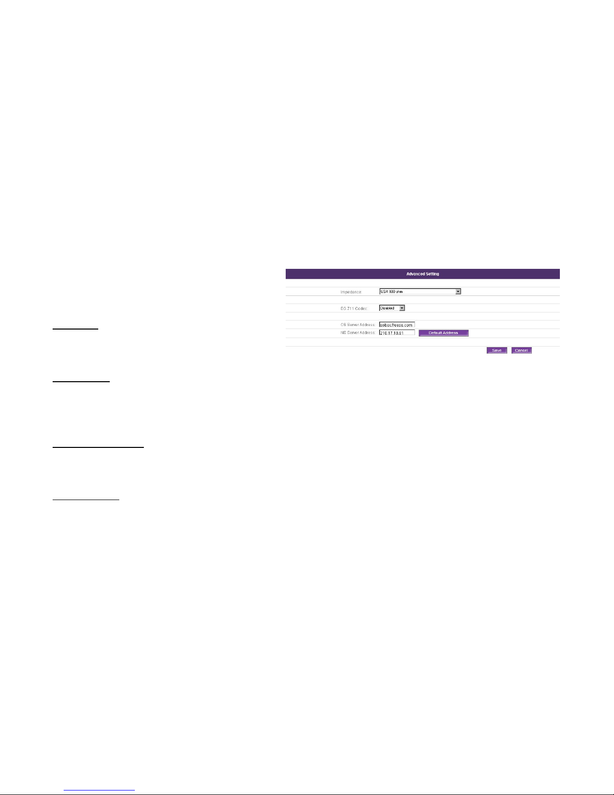
Telephony | Advanced Setting
In this page, you can configure the following Settings to
improve your voice quality.
Impedance
Specify the standard impedance for each country, default
is USA.
EG.711 Codec
To get higher voice quality, enabled EG.711 Codec is
recommended. But the broadband transmission is
suggested. EG.711 Codec is disabled by default.
CS/NS server address
The CS and NS server addresses are for the users who
already know the addresses, for example the enterprises.
Default Address
If you do not know the CS or NS server address, you may
click Default Address button to get the default CS or NS
server addresses, default CS server address is
ppbox.freepp.com while NS server address is
210.17.18.61.
Page 52

52
1. Select the Impedance base on your environment from
the dropdown list.
2. Enable EG.711 Codec to get higher voice quality.
3. Fill out the CS/NS server address if you already know
it, otherwise please click Default Address button to
get the default address.
4. Click Save button to save the entered values
Click Cancel button to restore all previous values.
5. The Apply button will blink after Save. Please click
Apply button to apply all the changes if necessary. All
the changes will be applied after reboot.
Page 53
53
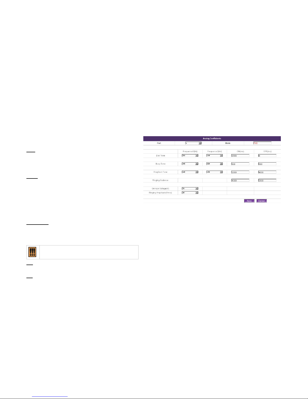
Telephony | Analog Coefficients
In this page, you can adjust the parameters for any analog
port to improve your telephony.
Port
Specify the current port number selected, range of
which is from 1 to 4.Default port number is 1.
Mode
Show the current port mode, such as FXS and FXO. In
this page, the port mode is fixed by the port number. So
you can not change its status. If you want to do some
change on the port mode, you may go back to Port
Setting page.
Frequency
You may adjust the frequency by selecting the value from
the dropdown list, base on local environment.
Frequency 1 can not be set 0Hz.
ON
Specify the time duration when the tone is on.
Off
Specify the time duration when the tone is off.
Page 54
54
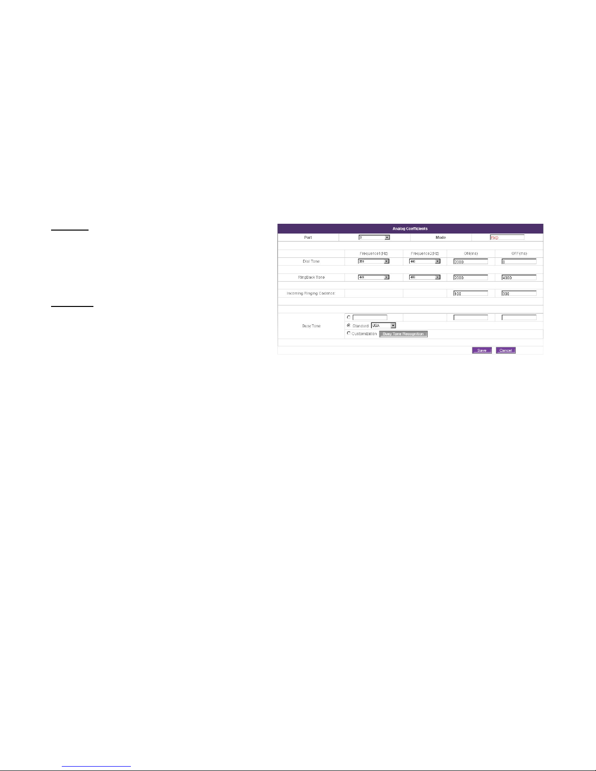
Dial Tone
A dial tone is a telephony signal used to indicate that the
telephone exchange is working and ready to accept a call.
The tone stops when the first numeral is dialed. Specify
the frequency and cadence for dial tone.
Busy Tone
A busy Tone (or engaged tone) in telephony is an
audible or visual signal to the calling party that indicates
failure to complete the requested connection of that
particular telephone call. Specify the frequency and
cadence for Busy tone.
You have three ways to set up Busy Tone parameters with
FXO interface:
1. Fill out Busy Tone Frequency and ON/OFF time in
the textbox manually if you already know it.
2. Select the country where you are located from the
dropdown list to get your local standard busy tone
frequency.
3. Click Busy Tone Recognition button to learn the busy
tone from your local telephone service and to get the
local standard busy tone frequency.
Busy Tone recognition is highly recommended.
Page 55

55
Ring back Tone
An audible ringing tone, or ringback tone (RBT) or
ringback signal, is the audible ringing that is heard on the
telephone line by the calling party after dialing and prior to
the call being answered at the distant end. Specify the
frequency and cadence for Ring back tone.
Ringing Cadence
In telephony, it refers to the ringing p attern heard by callee,
before they pick up the phone. Specify the cadence sent
by FXS.
Onhook Voltage
The value is set for the on-hook line voltage. Specify the
onhook voltage sent by FXS.
Ringing Amplitude
The voltage is set to ring the telephone connected to
MPES-4. Specify the voltage amplitude sent by FXS.
1. Select port number.
2. Enter and choose the coefficient of ringing tone
3. Click Save button to save the entered values.
Click Cancel button to restore all previous values.
4. The Apply button will blink after Save. Please click
Apply button to apply all the changes if necessary. All
the changes will be applied after reboot.
Page 56
56
Telephony | Analog Coefficients | Busy Tone Recognition
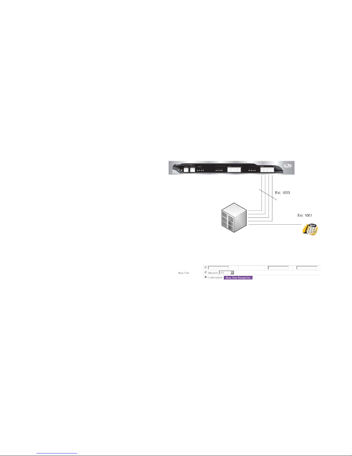
The figure displays the connection between MPES-4 and
PBX (Private Branch (telephone) Exchange).
To process the Busy Tone recognition, you could
another extension number to call the extension number
which connected with your MPES-4 after your connection
established.
Please click Busy Tone Recognition button to start the
procedure.
Page 57
57
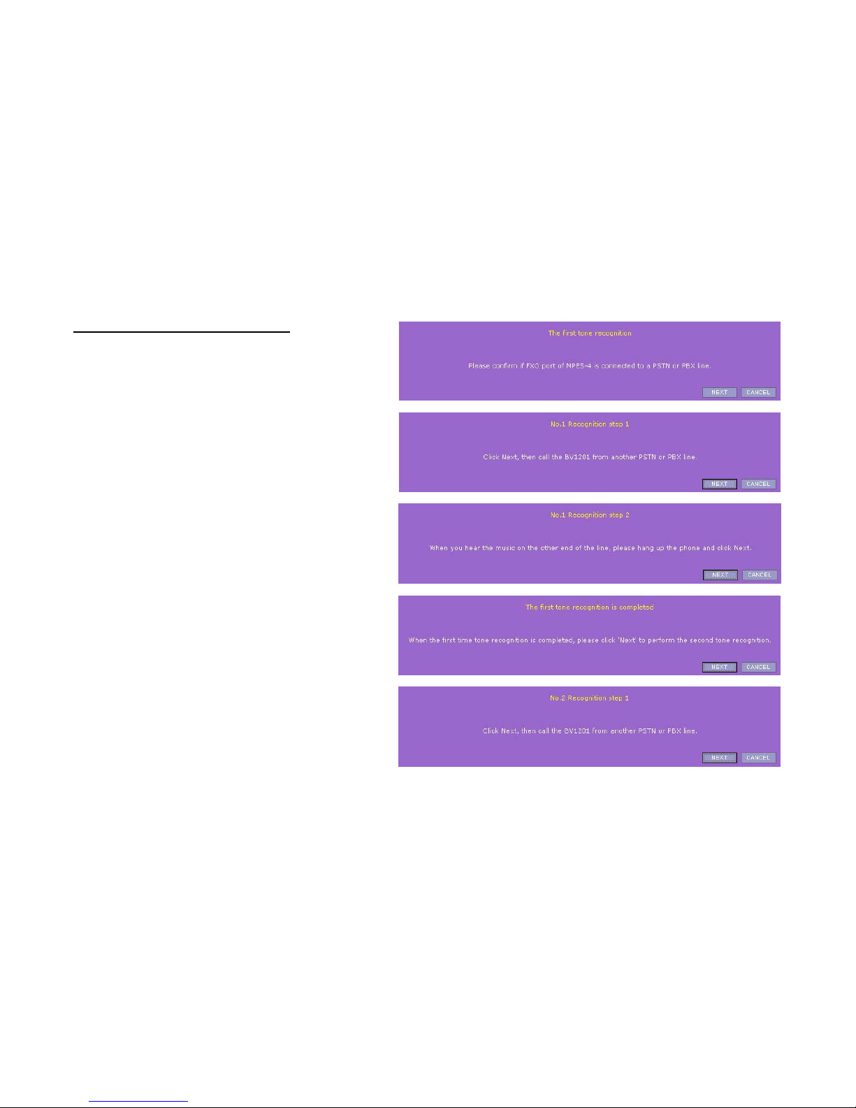
Busy Tone Recognition Process
Busy Tone Recognition process is to be completed by
three repeated steps.
1. Before go to busy tone recognition, please make sure
the FXO port of MPES-4 is connected to a line of PBX.
2. Please use another PBX line to call the MPES-4 (e.g. If
the PBX line (Ext #1000) is attached to the MPES-4
shown on above figures, please use another line (Ext
#1001) to call the MPES-4.
3. The First Tone Recognition is completed. Please
click NEXT button to start the second tone recognition.
The second and third tone recognition processes are just
the same as the first recognition process. Just repeat the
procedures above.
Page 58

58
4. Exit the recognition by clicking OK button when the
process is completed.
5. Click Save button to save the entered values.
Click Cancel button to restore all previous values.
6. The Apply button will blink after Save. Please click
Apply button to apply all the changes if necessary. All
the changes will be applied after reboot.
Note.
If the tone recognition has failed, please check the
connection and you could try again by clicking Redo
button.
Page 59
59
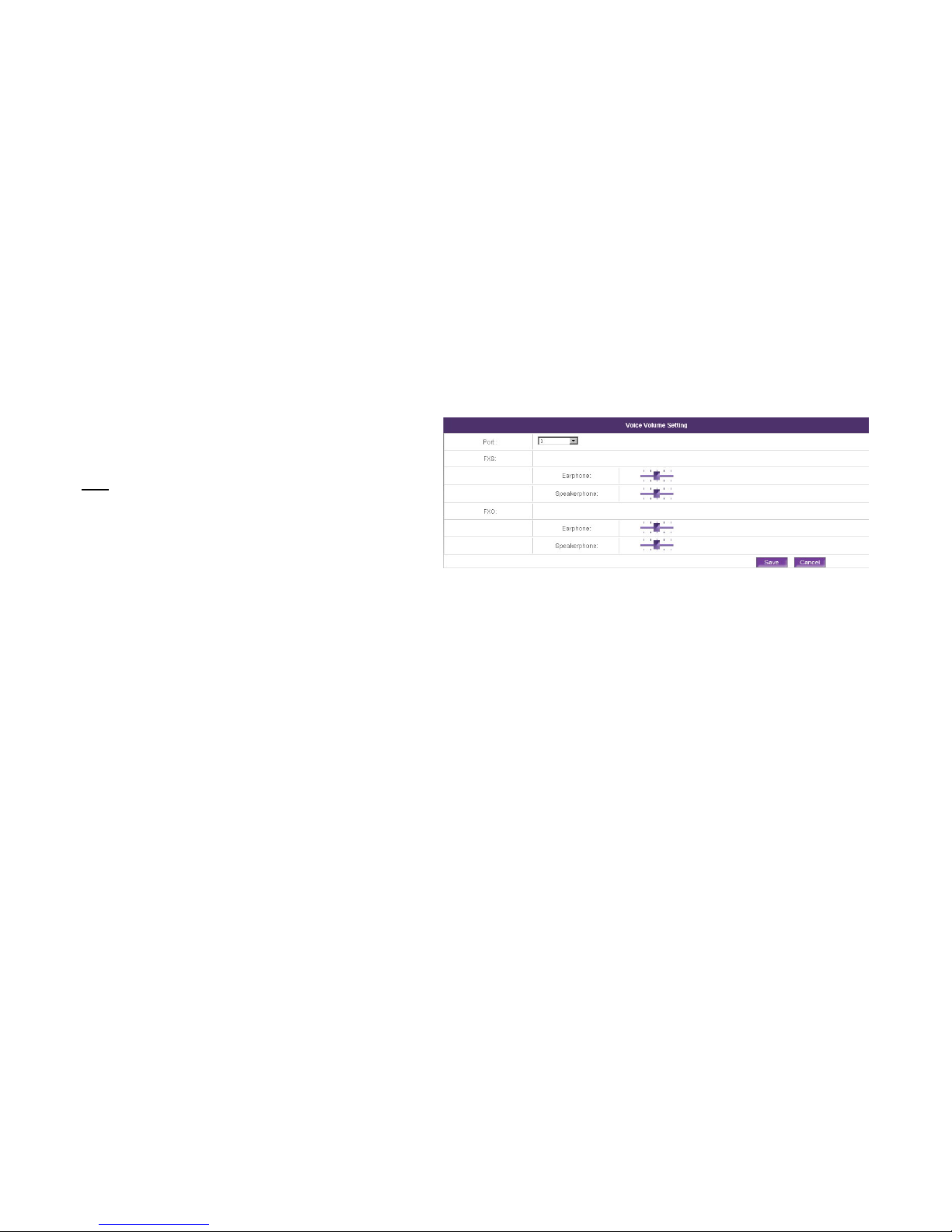
Telephony | Voice Volume Setting
You can adjust the voice volume over each port of the
MPES-4 in this page.
Port
Specify the telephone port number.
1. Select the port number which you want to adjust the
voice volume.
2. By moving the slide indicators as shown on the right,
you can change the voice volume level of both the FXS
and FXO port at the same time.
3. Click the Save button to save changes, when the voice
volume is adjusted. And the volume adjustment will take
effect immediately without reboot.
Click Cancel button to restore all previous values.
Page 60
60
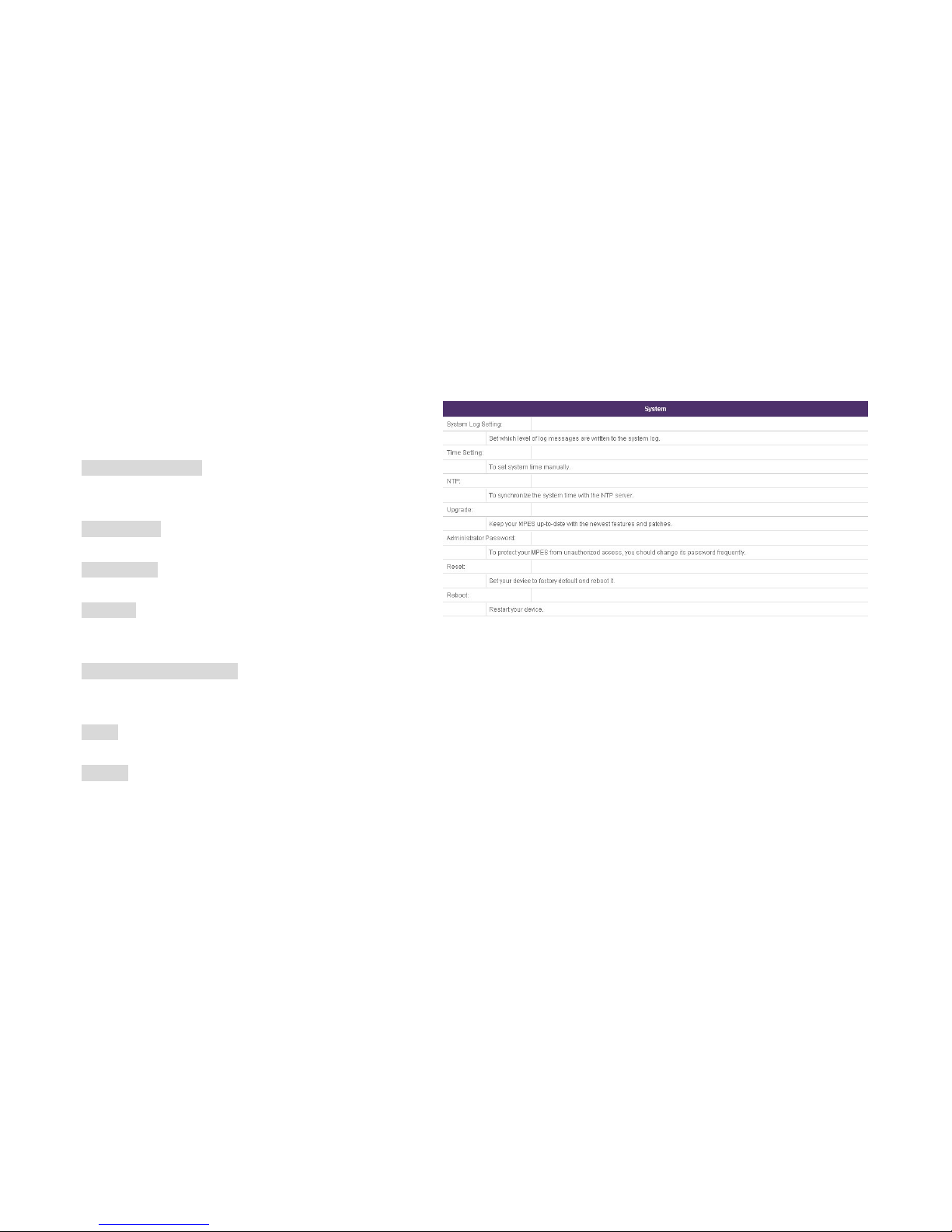
System
This page is to show System’s sub-menu and provide
quick access to each sub-menu by clicking on them.
System log setting
Set which level of log messages are written to the system
log.
Time setting
To set system time manually.
NTP Setting
To synchronize the system time with the NTP server.
Upgrade
Keep your MPES-4 up-to-date with the newest features
and patches.
Administrator Password
To protect your MPES-4 from unauthorized access, you
should change its password frequently.
Reset
Set your device to factory default and reboot it.
Reboot
Restart your device.
Page 61
61
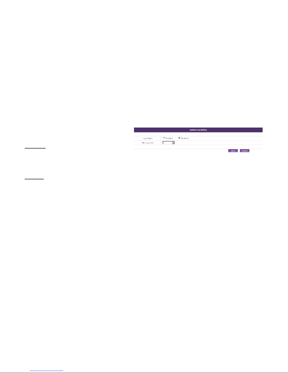
System | System log Setting
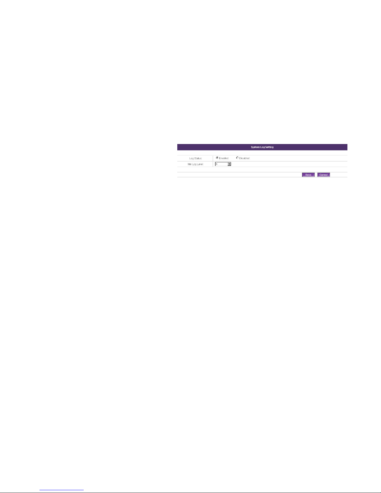
In this page, you can set the level of message to be written
to the system log.
Log Status
To enable or disable the MPES-4 to record the log on
server board. When disabled is selected and Log Level
are disabled accordingly.
Log Level
Specify the log message level from 1 to 5. One (1) means
the system will display the fewest amount of message;
otherwise, four (4) means the system will display the most
amount of message.
1. Enable the log status function.
2. Click Save button to save the entered values.
Click Cancel button to restore all previous values.
3. The Apply button will blink after Save. Please click
Apply button to apply all the changes if necessary. All
the changes will be applied after reboot.
Page 62

62
System | Time Setting
In this page, you can set system time for MPES-4
manually.
Date
Specify the date in format yyyy-mm-dd.
For example:2007-08-27.
Time
Specify the time in format hh:mm.
For example:16:02.
1. Fill out the Date and Time.
2. Click Save button to save the entered values. The time
setting will take effect immediately without reboot.
Click Cancel button to restore all previous values.
Page 63
63
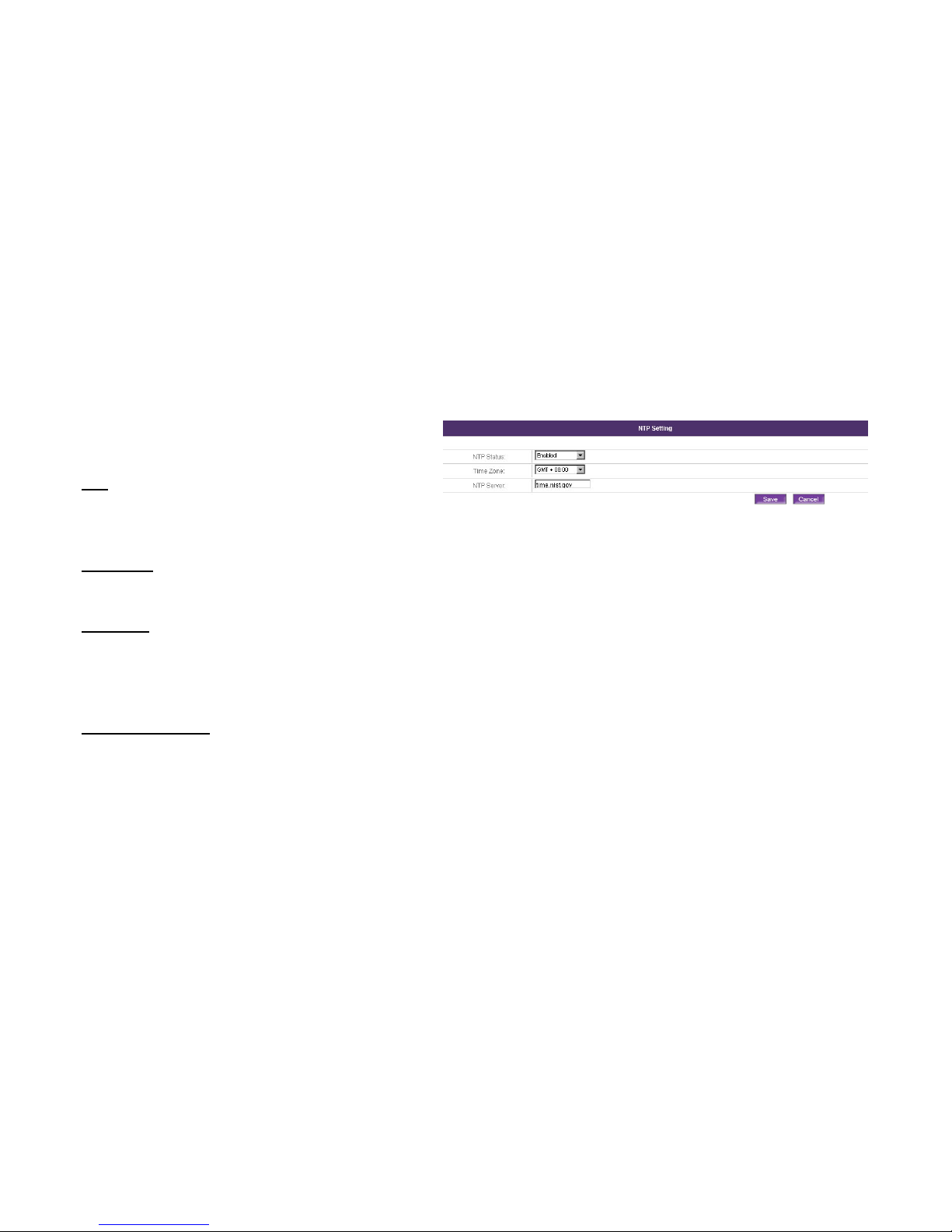
System | NTP Setting
In this page, you can synchronize MPES-4’ system time
with the NTP server.
NTP (Network Time Protocol)
It is used to synchronize the system time with the selected
network NTP server.
NTP Status
Specify to enable or disable this NTP service.
Time Zone
Specify the time zone base on MPES-4’s environment.
NTP Server Either domain name or IP address is
acceptable for NTP Server.
NTP Server address
You could refer to the NTP address for inputting as below.
time-a.nist.gov
time.nist.gov
time.windows.com
Page 64
64
1. Enable NTP service, select the Time Zone at which you
are located from the dropdown list. Set a reasonable
NTP Server in the textbox.
2. Click Save button to save the entered values.
Click Cancel button to restore all previous values.
3. The Apply button will blink after Save. Please click
Apply button to apply all the changes if necessary. All
the changes will be applied after reboot.
1. It is required to add at least one NTP server before enabling NTP service.
2. Time Synchronization will happen once a week, only at when your MPES-4 is connected to Internet.
Page 65
65
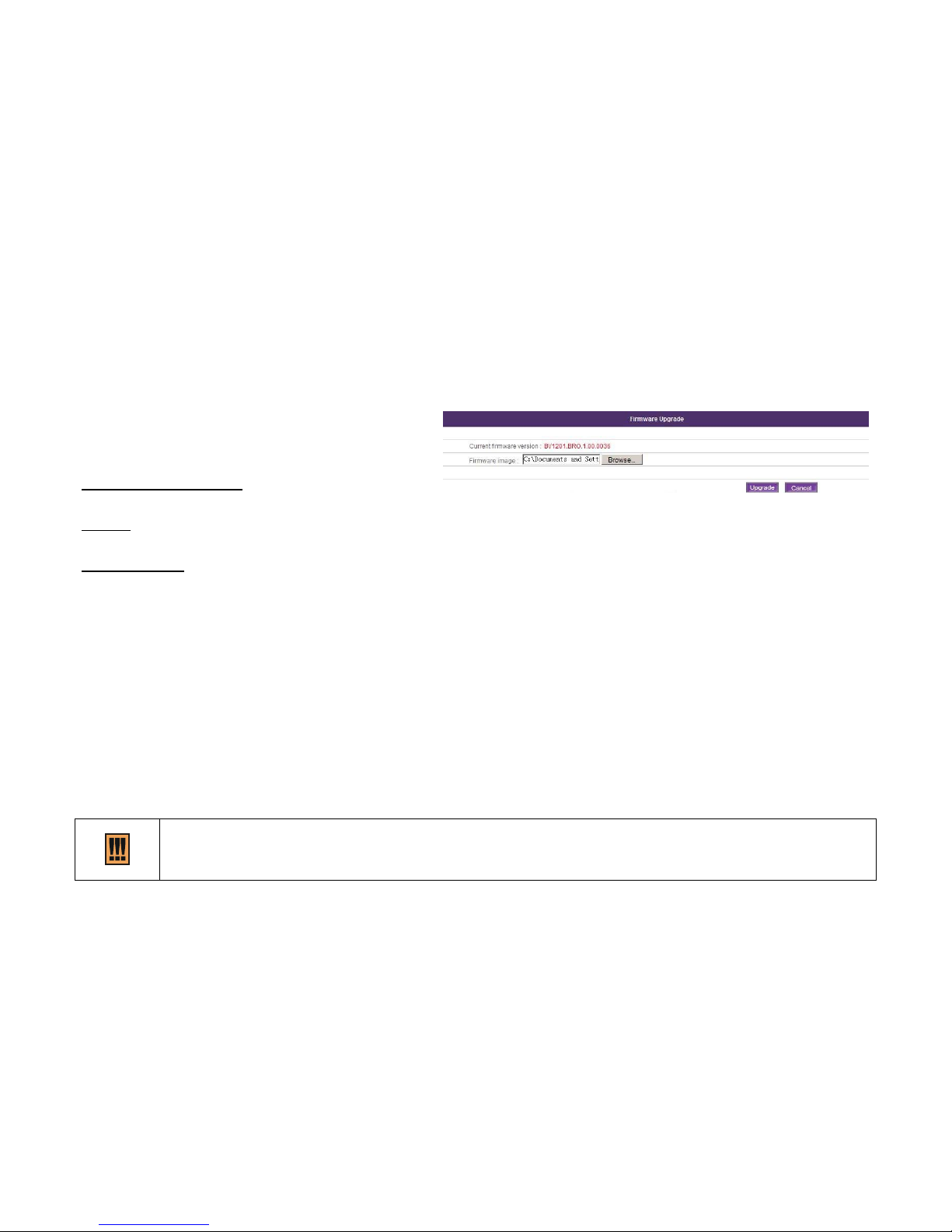
System | Upgrade (Firmware Upgrade)
In this page, you can keep your MPES-4 up-to-date with
the newest features and patches by upgrading the
Firmware.
Current firmware version
To show the current firmware version.
Browse
To upload the latest firmware by clicking Browse button.
Firmware Image
Specify the full path of the new firmware image.
1. Click Browse button to locate the latest firmware.
2. Click Upgrade button to upgrade the firmware. The
process will take a few minutes, please wait for a while.
Click Cancel button to restore all previous values.
Update firmware will take about 4 minutes.
3. Upgrade successfully window will appear when the
upgrading process finishes. And you need not restart
your MPES-4.
Do not switch off and do not disconnect the MPES-4 from the power supply during the firmware update process
because the device could be damaged. It is best to use the Ethernet connection (not wireless) for the firmware update
process.
Page 66
66
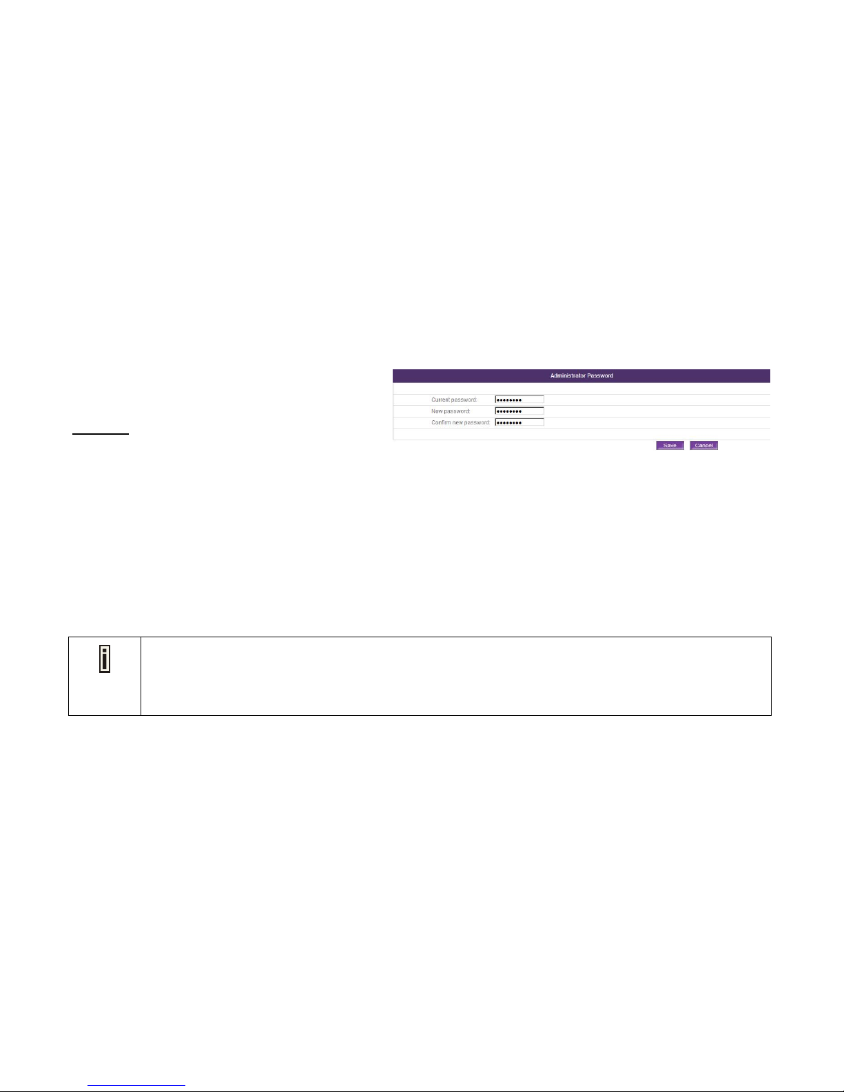
System | Administrator Password
To protect the MPES-4 from unauthorized access, you can
change the password in this page.
Password
The password should be a 6 to 16-digit number. English
characters (A-Z or a-z) and other characters will not be
accepted.
1. Fill out the Current password, the NEW password
and Confirm the new password,
2. Click Save button to apply the changes, the password
changes will take effect immediately without reboot.
Click Cancel button to restore all previous values.
1. Remember that the current password must be entered before saving the changes you have made. This will
prevent someone from modifying your MPES-4 illegally without your approval. You can find the default
password on the ID card or use the new password that you changed before.
2. Please be noted that the new password will be deleted after you reset the MPES-4 to the default settings.
Page 67
67
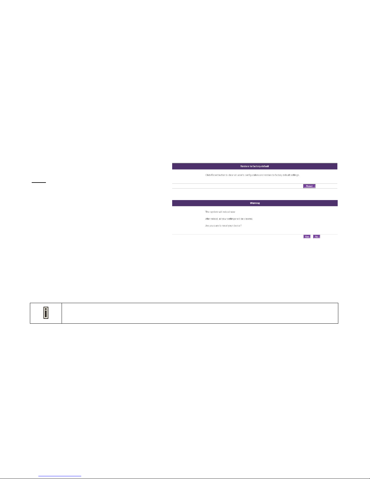
System | Reset (Restore to factory default)
You can set your device to factory default and reboot it.
Reset
To clear all the configurations and restore to factory default
settings.
1. Click Reset button, then a Warning page will appear to
make sure whether you will continue to clear all user's
configuration and restore to factory default settings or
not.
2. Click YES to reboot your MPES-4. All you settings will
be cleared after reboot.
Click NO to discard the reboot and go back to Reset
page.
3. It will take a few minutes to reboot. Please wait for a
while.
Please be noted that all settings including the administrator settings will be set back to the factory default when
Reset is selected.
Page 68
68
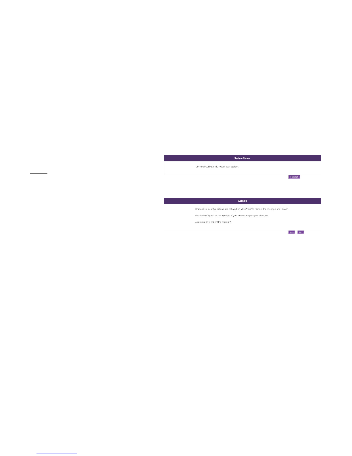
System | System Reboot
In this page, you can Restart your device.
Reboot
To restart your device.
1. Click Reboot button to restart your MPES-4, then a
Warning page will appear to make sure.
2. Click YES button to discard the changes and reboot.
3. Click NO to go back to the Reboot page.
It will take around 30 seconds to reboot. Please wait for a
while.
Page 69
69
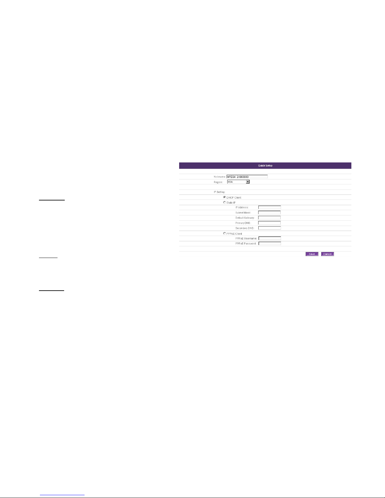
Quick Setup
Use Quick Setup to select the region where you are in and
set up the network environment. Please configure the
setting as your need.
1. Nickname
For your convenience, you could create a nickname for
the MPES-4, this will facilitate other users who have
added the ID of MPES-4 in contact list of their
softphone.
The default nickname is MPES4_ID.
(ex. MPES4_24980060)
2. Region
To specify the region where MPES-4 is located. Default
region is USA. And you can select the region yourself
from the drop-down list.
3. IP Setting
To setup the basic parameter to connect the network.
There are three ways to implement the IP Setting.
a. DHCP
Client Obtain an IP address automatically.
b. Static IP
Use the specified static IP address.
Page 70
70
c. PPPoE Client
Broadband connection with a username and
password.
Quick setup page is the default page when you log in MPES-4 with factory default setting.
The MPES-4 is set as DHCP client by default.
If you are not familiar with these settings, please consult the network administrator.
Page 71
71
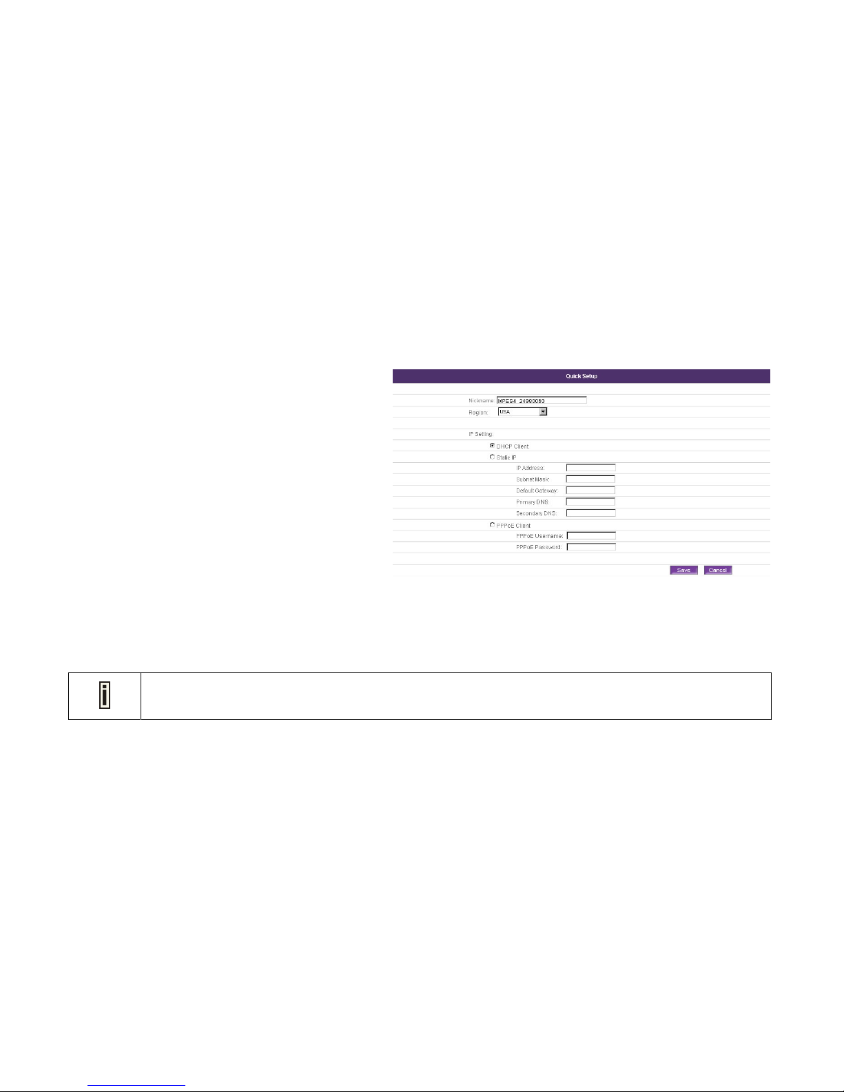
Quick Setup | IP Setting | DHCP Client
DHCP Client is the default option. If you are not very sure
about the IP setting for the MPES-4, choose DHCP Client
mode. The MPES-4 will use an assigned IP address from
your network router or gateway. Otherwise, MPES-4 will
intelligently try all possible IP settings in the cache memory
to connect your MPES-4 to the network.
DHCP
Dynamic Host Configuration Protocol.
1. Select DHCP Client.
2. Click Save button to save the entered values.
Click Cancel button to restore all previous values.
3. The Apply button will blink after Save. Please click
Apply button to apply all the changes if necessary. All
the changes will be applied after reboot.
The MPES-4 has a DHCP server embedded. That means by enabling the router mode, the MPES-4 will assign a
dynamic IP to the device connected to the Configuration port of your MPES-4.
Page 72
72
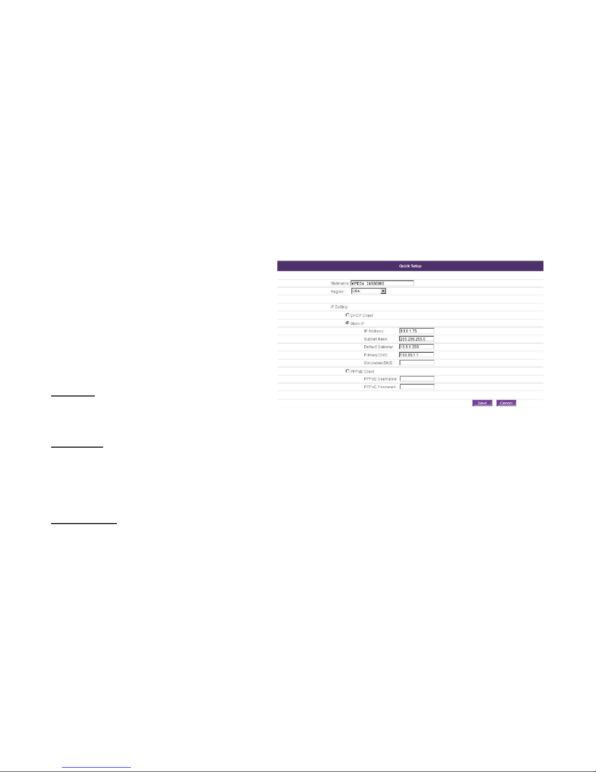
Quick Setup | IP Setting | Static IP
In this page, you can use the specified static IP address
to configure your MPES-4.
If your MPES-4 has been allocated a specified static IP
address, please fill out the necessary IP settings here. If
you are not familiar with these settings, please consult the
network administrator.
Static IP
Use the specified static IP address.
IP Address
Specified IP address for your MPES-4 in digits and dots
notation ([0-255]. [0-255]. [0-255]. [0-255], e.g.
192.168.121.70).
Subnet Mask
Specified Subnet Mask for your MPES-4 in digits and dots
notation ([0-255]. [0-255]. [0-255]. [0-255], e.g.
255.255.252.0]). These numbers are a binary mask of the
IP address, which defines IP address order and the
number of IP addresses in the subnet.
Default Gateway
Specified the interface gateway in digits and dots notation
([0-255]. [0-255]. [0-255]. [0-255], e.g. 192.168.123.1)
Page 73
73
Primary DNS
Specified the DNS server’s IP address in digits and dots
notation ([0-255]. [0-255]. [0-255]. [0-255], e.g.
202.96.209.5).
Secondary DNS
Specified the secondary DNS server’s IP address in digits
and dots notation ([0-255]. [0-255]. [0-255]. [0-255], e.g.
202.96.209.13). Or you can leave it blank.
1. Select Static IP.
2. Fill out IP Address, Subnet Mask, Default Gateway,
DNS settings.
3. Click Save button to save the entered values. MPES-4
will check if the entered values are valid automatically
before saving them.
Click Cancel button to restore all previous values.
4. The Apply button will blink after Save. Please click
Apply button to apply all the changes if necessary. All
the changes will be applied after reboot.
1. The Secondary DNS can be left blank while Primary DNS can not be blank.
2. The Secondary DNS can not be with the same value as Primary DNS.
Page 74
74
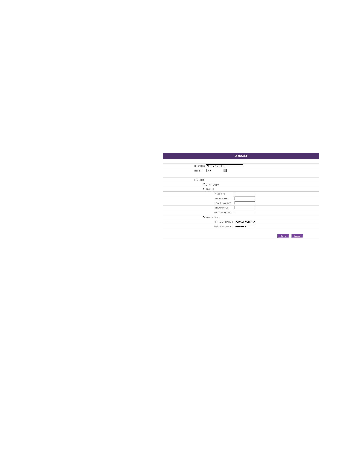
Quick Setup | IP Setting | PPPoE Client
PPPoE Stands for Point-to-Point Protocol over Ethernet.
PPPoE is a specification for connecting the users on an
Ethernet to the Internet through a common broadband
medium, such as a single DSL line, wireless device or
cable modem.
PPPoE Username/Password
Direct cable connection needs username and password.
1. Fill out your PPPoE Username and password.
2. Click Save button to save the entered values.
Click Cancel button to restore all previous values.
3. The Apply button will blink after Save. Please click
Apply button to apply all the changes if necessary. All
the changes will be applied after reboot.
Page 75
75
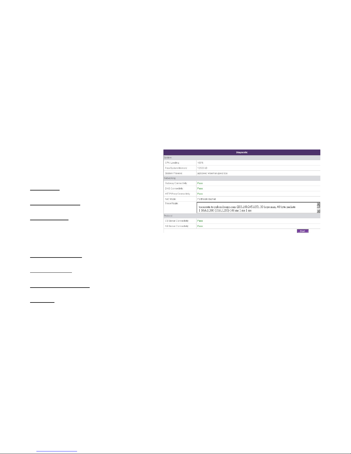
Diagnostic
This page allows you to check the MPES-4 current
information, including System, Networking and Protocol.
System
CPU loading
Show the current CPU loading in percentage.
Free System Memory
Show the current free system memory.
System Process
Show the current running process.
Networking
Gateway Connectivity
Show whether Gateway is connected or not.
DNS Connectivity
Show whether DNS is connected or not.
HTTP Proxy Connectivity
Show whether HTTP Proxy is connected or not.
NAT Mode
Specify the current NAT Mode, including Direct-Connect,
IP-Restrict, Port-Restrict, Symmetric and Unknown.
Page 76
76
Trace Route
Show the trace route result in row in the textbox.
Protocol
CS Server Connectivity
Show whether CS Server is connected or not.
NS Server Connectivity
Show whether NS Server is connected or not.
Click Start button to start the diagnostic process.
No any other action is enabled during the diagnostic process.
Page 77
77
Chapter 6: Making FreePP Calls
Place FreePP On-Net Calls
1. Dial FreePP ID directly to reach your friends.
For example: call FreePP ID: 24000001 please dial: 24000001
FreePP On-Net call is free.
Place FreePP Outbound Calls (FreePP OUT Service)
Make a domestic or international call by FreePP to a regular telephone or a mobile. Please note that the MPES should be activated
for FreePP OUT service and has enough credits in its account. You can buy FreePP credit on the FreePP website
http://www.freepp.com
1. Dial 00 country code area code phone number
For example: call Taipei City Government, T aiwan (Tel: 886-2-27208889), please dial: 00886227208889.
2. You can hear the voice response reported your available credit for making FreePP outbound calls.
1. Please refer to Chapter 7 to add your credit to your account.
2. Please refer to the FreePP service rate on the FreePP website when you make an outbound call.
Page 78

78
Chapter 7: Adding FreePP Credit
Add FreePP Credit to your FreePP account
1. Go to FreePP website http://www.freepp.com
2. Click Buy Credit button to enter my account page.
3. Enter the ID and password of MPES.
4. Fill out your personal information.
5. Click the Add-Credit button to enter the payment page.
6. Select the payment method.
Page 79

79
Chapter 8: Appendix
FCC REQUIREMENTS
This equipment complies with Part 68 of the FCC rules and the requirements adopted by the ACTA. On the bass unit of this
equipment is a label that contains, among other information, a product identifier in the format US: GEMIT00BV1201. If requested, this
number must be provided to the telephone company.
The REN is used to determine the number of devices that may be connected to a telephone line. Excessive RENs on a telephone line
may result in the devices not ringing in response to an incoming call. In most but not all areas, the sum of RENs should not exceed five
(5.0). To be certain of the number of devices that may be connected to a line, as determined by the total RENs, contact the local
telephone company. For products approved after July 23, 2001, the REN for this product is part of the product identifier that has the
format US: AAAEQ##TXXXX. The digits represented by ## are the REN without a decimal point (e.g., 03 is a REN of 0.3). For earlier
products, the REN is separately shown on the label.
If your equipment causes harm to the telephone network, the telephone company may discontinue your service temporarily. If
possible, they will notify you in advance. But if advance notice is not practical, you will be notified as soon as possible. You will be
informed of your right to file a complaint with the FCC. Your telephone company may make changes in its facilities, equipment,
operations or procedures that could affect the proper functioning of your equipment. If they do, you will be notified in advance to give
you an opportunity to maintain uninterrupted telephone service.
If you experience trouble with this telephone equipment, please contact the following address and phone number for information on
obtaining service or repairs.
The telephone company may ask that you disconnect this equipment from the network until the problem has been corrected or until
you are sure that the equipment is not malfunctioning.
Page 80

80
This equipment may not be used on coin service provided by the telephone company. Connection to party lines is subject to state
tariffs.
Company: Charlink Corporation
Address: One Market Plaza, Steuart Tower, Suite 2630,San Francisco, CA 94105, U.S.A
Tel no.: 415 576 0700
A plug and jack used to connect this equipment to the premises wiring and telephone network must comply with the applicable FCC
Part 68 rules and requirements adopted by the ACTA. A compliant telephone cord and modular plug is provided with this product. It is
designed to be connected to a compatible modular jack that is also compliant. See installation instructions for details.
 Loading...