

Page 1
Model No. SFSR84409.1
Serial No.
Write the serial number in the
space above for reference.
Serial
Number
Decal
QUESTIONS?
If you have questions, or if parts
are damaged or missing, CONTACT
THE STORE WHERE YOU PURCHASED THIS PRODUCT.
If you are unable to contact the
store, see HOW TO CONTACT
CUSTOMER CARE on the back
cover of this manual.
USERʼS MANUAL
CAUTION
Read all precautions and instructions in this manual before using
this equipment. Keep this manual
for future reference.
www.freemotionfitness.com
Page 2
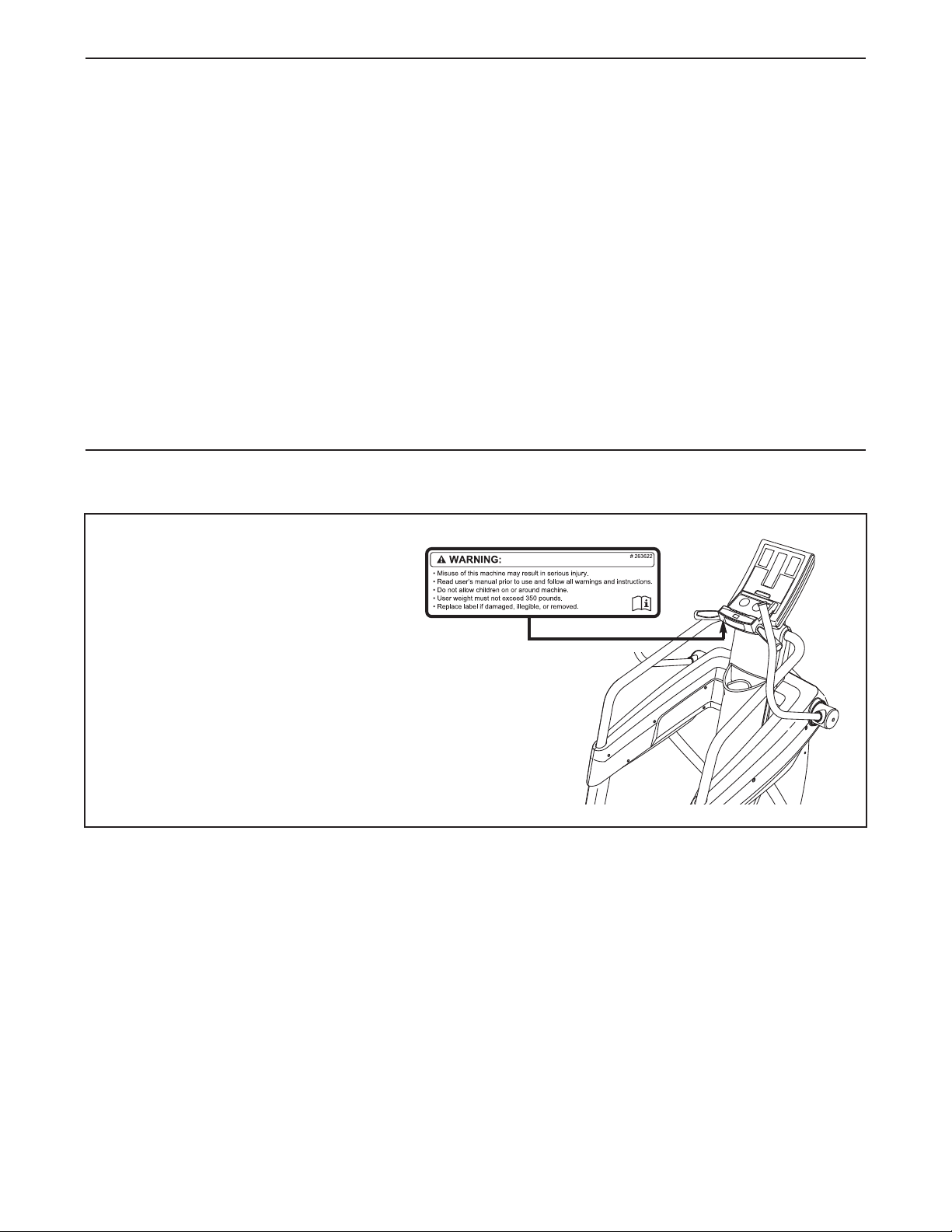
TABLE OF CONTENTS
WARNING DECAL PLACEMENT . . . . . . . . . . . . . . . . . . . . . . . . . . . . . . . . . . . . . . . . . . . . . . . . . . . . . . . . . . . . . .2
MPORTANT PRECAUTIONS . . . . . . . . . . . . . . . . . . . . . . . . . . . . . . . . . . . . . . . . . . . . . . . . . . . . . . . . . . . . . . . .3
I
BEFORE YOU BEGIN . . . . . . . . . . . . . . . . . . . . . . . . . . . . . . . . . . . . . . . . . . . . . . . . . . . . . . . . . . . . . . . . . . . . . .4
ASSEMBLY . . . . . . . . . . . . . . . . . . . . . . . . . . . . . . . . . . . . . . . . . . . . . . . . . . . . . . . . . . . . . . . . . . . . . . . . . . . . . . .5
HOW TO USE THE STRIDER . . . . . . . . . . . . . . . . . . . . . . . . . . . . . . . . . . . . . . . . . . . . . . . . . . . . . . . . . . . . . . . .6
HOW TO USE THE CONSOLE . . . . . . . . . . . . . . . . . . . . . . . . . . . . . . . . . . . . . . . . . . . . . . . . . . . . . . . . . . . . . . .8
MAINTENANCE AND TROUBLESHOOTING . . . . . . . . . . . . . . . . . . . . . . . . . . . . . . . . . . . . . . . . . . . . . . . . . . .15
EXERCISE GUIDELINES . . . . . . . . . . . . . . . . . . . . . . . . . . . . . . . . . . . . . . . . . . . . . . . . . . . . . . . . . . . . . . . . . . .16
PART LIST . . . . . . . . . . . . . . . . . . . . . . . . . . . . . . . . . . . . . . . . . . . . . . . . . . . . . . . . . . . . . . . . . . . . . . . . . . . . . .19
EXPLODED DRAWING . . . . . . . . . . . . . . . . . . . . . . . . . . . . . . . . . . . . . . . . . . . . . . . . . . . . . . . . . . . . . . . . . . . .21
HOW TO CONTACT CUSTOMER CARE . . . . . . . . . . . . . . . . . . . . . . . . . . . . . . . . . . . . . . . . . . . . . . .Back Cover
LIMITED WARRANTY . . . . . . . . . . . . . . . . . . . . . . . . . . . . . . . . . . . . . . . . . . . . . . . . . . . . . . . . . . . . . .Back Cover
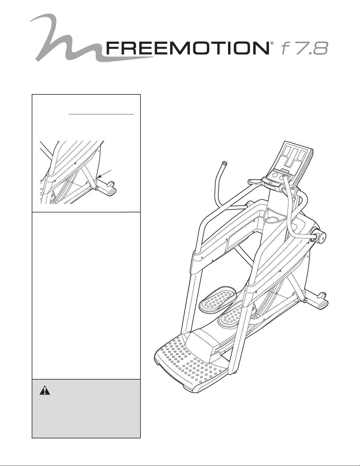
WARNING DECAL PLACEMENT
This drawing shows the location(s)
of the warning decal(s). If a decal is
missing or illegible, see the back
cover of this manual and request
a free replacement decal. Apply
the decal in the location shown.
Note: The decal(s) may not be
shown at actual size.
FREEMOTION is a registered trademark of ICON IP, Inc.
iPod is a trademark of Apple Computer, Inc., registered in the U.S. and other countries. iPod®is not included.
2
Page 3

IMPORTANT PRECAUTIONS
o reduce the risk of serious injury, read all important precautions and
WARNING:
instructions in this manual and all warnings on your strider before using your strider. FreeMotion
Fitness assumes no responsibility for personal injury or property damage sustained by or through
the use of this product.
T
1. Before beginning any exercise program,
consult your physician. This is especially
important for persons over age 35 or persons with pre-existing health problems.
2. Use the strider only as described in this
manual.
3. It is the responsibility of the owner to ensure
that all users of the strider are adequately
informed of all precautions.
4. Keep the strider indoors, away from moisture and dust. Do not put the strider in a
garage or covered patio, or near water.
5. Place the strider on a level surface, with at
least 3 ft. (0.9 m) of clearance in the front
and rear of the strider and 2 ft. (0.6 m) on
each side. To protect the floor or carpet from
damage, place a mat under the strider.
6. Inspect and properly tighten all parts regularly. Replace any worn parts immediately.
7. Keep children under age 12 and pets away
from the strider at all times.
8. The strider should not be used by persons
weighing more than 350 lbs. (159 kg).
9. Wear appropriate clothes while exercising;
do not wear loose clothes that could become
caught on the strider. Always wear athletic
shoes for foot protection while exercising.
10. Hold the handgrip pulse sensors, the handlebars, or the handrails when mounting,
dismounting, or using the strider.
11. The pulse sensor is not a medical device.
Various factors may affect the accuracy of
heart rate readings. The pulse sensor is
intended only as an exercise aid in determining heart rate trends in general.
12. Keep your back straight while using the
strider; do not arch your back.
13. Over exercising may result in serious injury
or death. If you feel faint or if you experience
pain while exercising, stop immediately and
cool down.
14. When you stop exercising, allow the pedals
to slowly come to a stop.
15. Over exercising may result in serious injury
or death. If you feel faint or if you experience
pain while exercising, stop immediately and
cool down.
3
Page 4
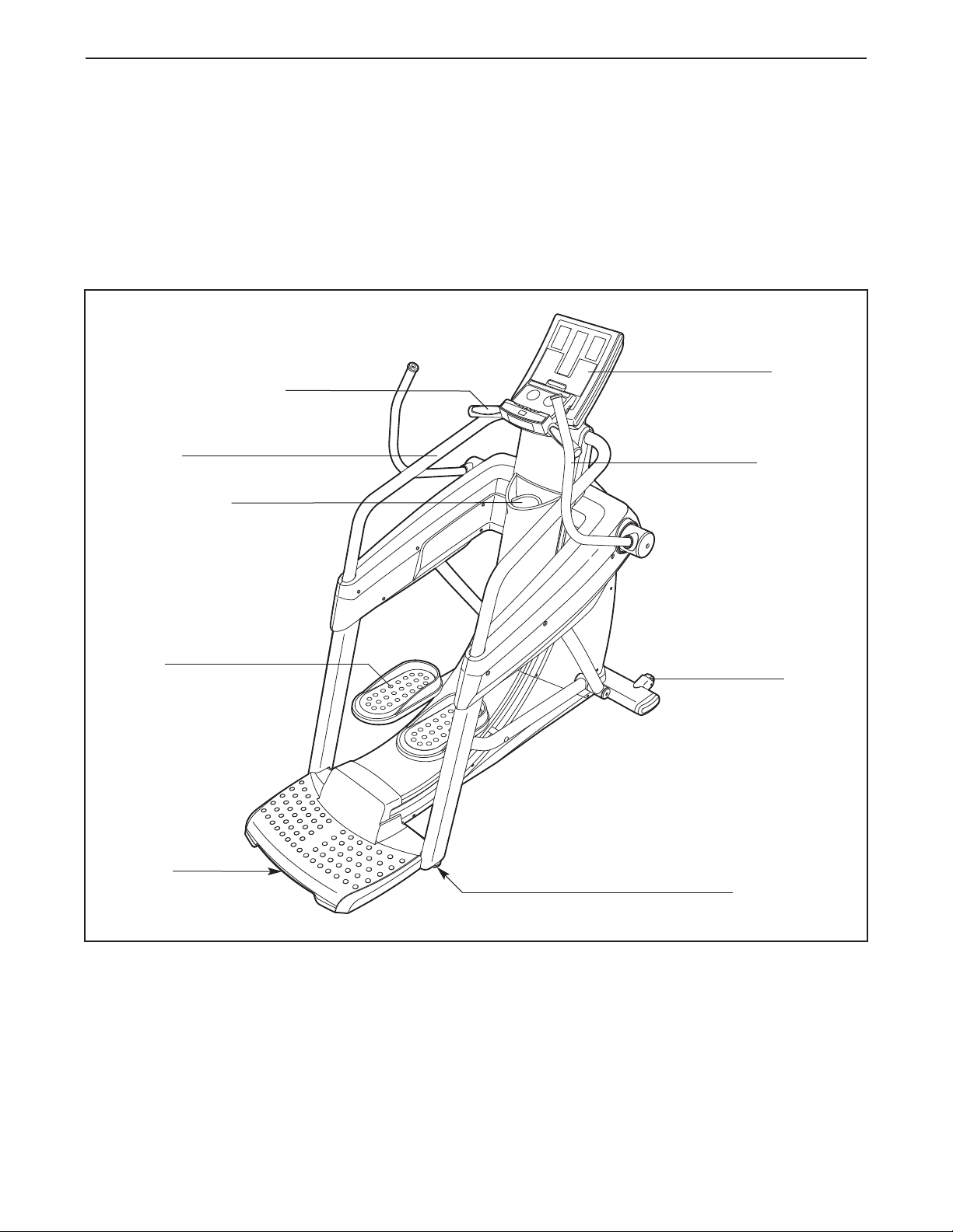
BEFORE YOU BEGIN
Thank you for selecting the revolutionary
FREEMOTION®F 7.8 strider. The F 7.8 strider pro-
ides an impressive selection of features designed to
v
make your workouts at home more effective and
enjoyable.
For your benefit, read this manual carefully before
you use the strider. If you have questions after read-
Handgrip Pulse Sensor
Handrail
Accessory Tray
ing this manual, please see the back cover of this
manual. To help us assist you, note the product model
umber and serial number before contacting us. The
n
model number and the location of the serial number
decal are shown on the front cover of this manual.
Before reading further, please familiarize yourself with
the parts that are labeled in the drawing below.
Console
Handlebar
Pedal
Handle
Wheel
Leveling Foot
4
Page 5
ASSEMBLY
Assembly requires two persons. Place all parts of the strider in a cleared area and remove the packing mate-
rials. Do not dispose of the packing materials until assembly is completed.
Assembly requires only the included tool(s).
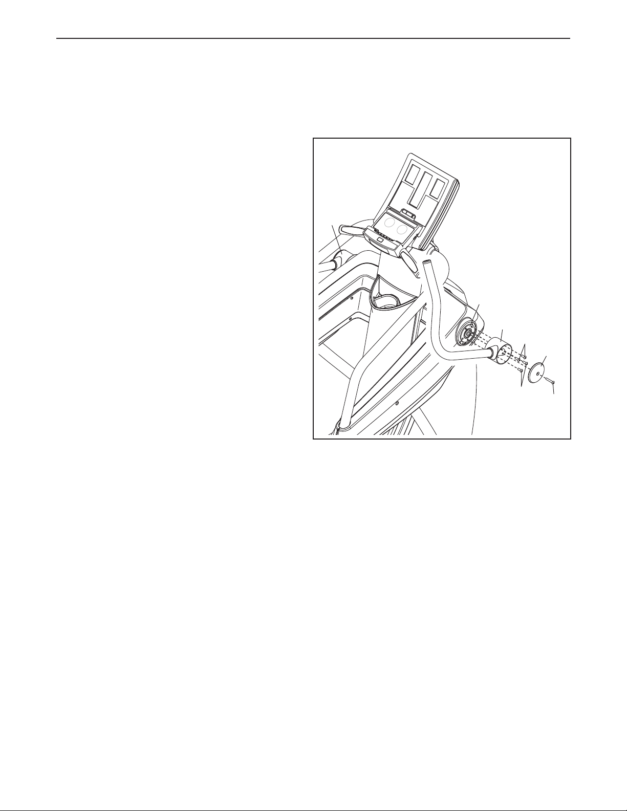
. Hold the lower end of the Right Handlebar (20)
1
against the Right Handlebar Hub (30), and align
the five holes in the Right Handlebar with the
five holes in the Right Handlebar Hub.
Attach the Right Handlebar (20) with four 5/16"
x 3/4" Patch Screws (105).
Next, attach a Handlebar Cover (43) to the
Right Handlebar (20) with a 5/16" x 1 3/8"
Screw (106).
1
21
Attach the Left Handlebar (21) in the same
way.
2. Make sure that all parts of the strider are properly tightened. To protect the floor or carpet from damage,
place a mat under the strider.
30
20
105
105
43
106
5
Page 6
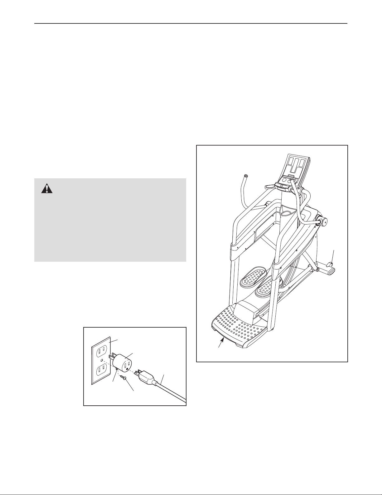
HOW TO USE THE STRIDER
HOW TO PLUG IN THE AC POWER ADAPTER
This product must be grounded. If it should mal-
function or break down, grounding provides a path of
least resistance for electric current to reduce the risk
f electric shock. This product is equipped with a cord
o
having an equipment-grounding conductor and a
grounding plug.
Plug the AC power adapter into an appropriate
outlet that is properly installed and grounded in
accordance with all local codes and ordinances.
This product is for use on a nominal 120-volt circuit. IMPORTANT: The strider is not compatible
with GFCI-equipped outlets and may not be compatible with AFCI-equipped outlets.
DANGER: Improper connection of
the equipment-grounding conductor can
result in an increased risk of electric shock.
Check with a qualified electrician or serviceman if you are in doubt as to whether the
product is properly grounded. Do not modify
the plug provided with the product—if it will
not fit the outlet, have a proper outlet installed
by a qualified electrician.
HOW TO MOVE THE STRIDER
Due to the size and weight of the strider, moving it
requires two persons. Have two persons lift the indi-
cated end of the strider until the strider will roll on the
ront wheels. Carefully move the strider to the desired
f
location and then lower it to the level position.
CAUTION: To decrease the risk of injury, bend
your legs and keep your back straight. Make sure
to use your legs rather than your back to lift the
strider. Do not attempt to move the strider over an
uneven surface.
Wheel
A temporary adapter may be used to connect the AC
power adapter to a 2-pole receptacle as shown below
if a properly grounded outlet is not available. The temporary adapter should be used only until a properly
grounded outlet can be installed by a qualified electrician.
The greencolored rigid
ear, lug, or
the like
extending
from the
adapter must
be connected
to a permanent ground
such as a
properly
grounded outlet box cover. Whenever the adapter is
used, it must be held in place by a metal screw. Some
2-pole receptacle outlet box covers are not
grounded. Contact a qualified electrician to determine if the outlet box cover is grounded before
using an adapter.
Grounded Outlet Box
Adapter
AC Power
Adapter
Lug
Metal Screw
Lift here
6
Page 7
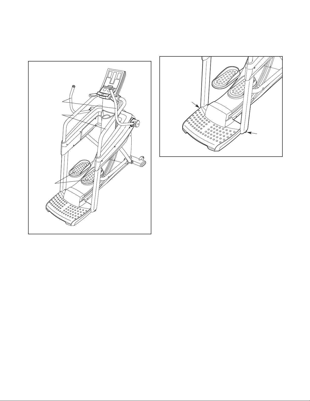
OW TO EXERCISE ON THE STRIDER
H
OW TO LEVEL THE STRIDER
H
To mount the strider, hold the handlebars or the
handrails and step onto the pedals. Push the pedals
until they begin to move forward and backward with a
continuous motion.
Handlebars
Handrails
If the strider rocks slightly on your floor during use,
turn one or both of the leveling feet beneath the rear
of the frame until the rocking motion is eliminated.
Leveling
Foot
Leveling
Foot
Pedals
To dismount the strider, wait until the pedals come to a
complete stop. When the pedals are stationary, hold
the handlebars or the handrails and step off the pedals.
7
Page 8
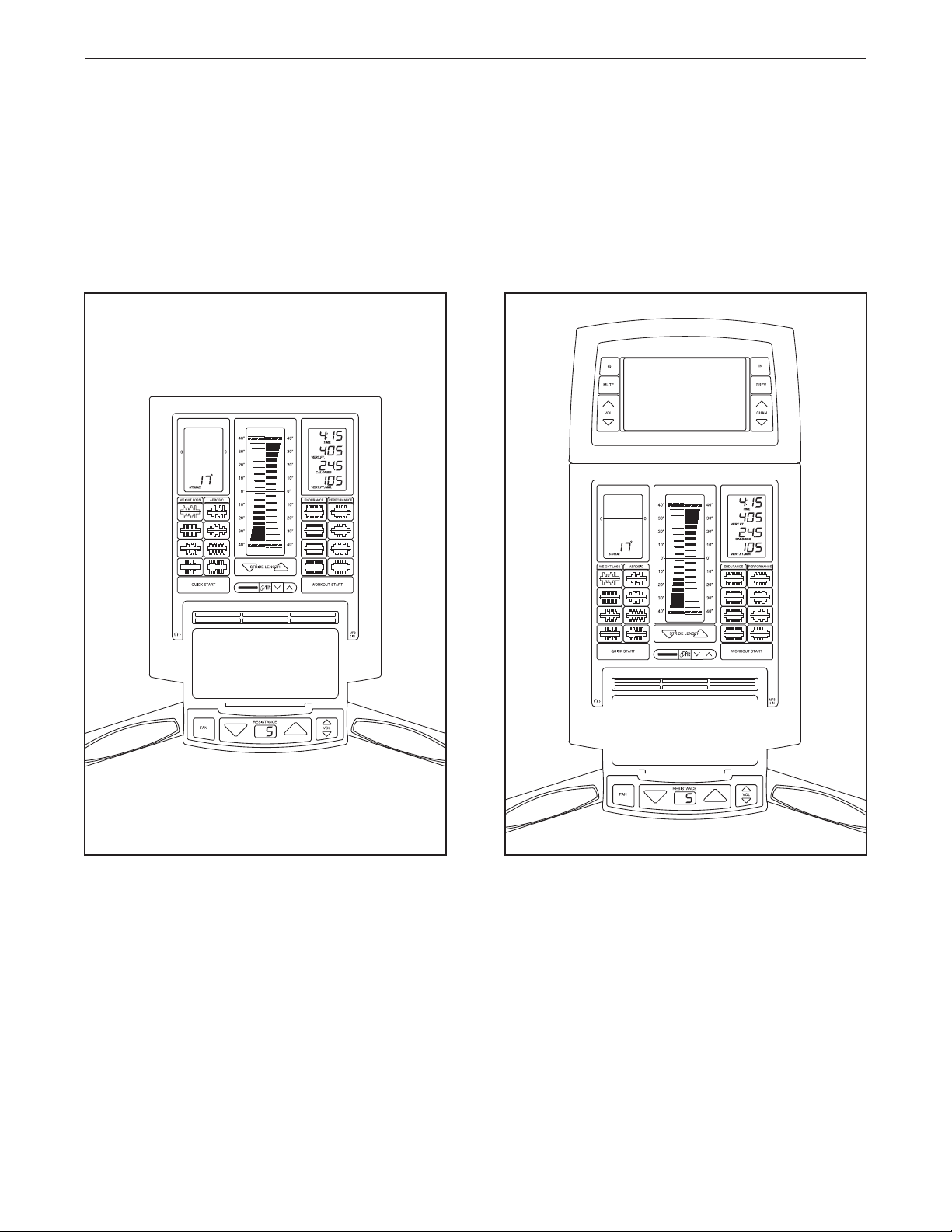
HOW TO USE THE CONSOLE
HOW TO UPGRADE THE CONSOLE
Your strider has been preconfigured to operate with a Basic console and a Workout TV console (see the drawings below). To learn about the features of the Basic console, see page 9. To learn about the features of the
Workout TV console, see the userʼs manual included with the Workout TV console.
To upgrade your console and expand the capabilities of your strider, please see the back cover of this
manual.
Basic
Console
Workout TV
Console
8
Page 9

CONSOLE DIAGRAM
FEATURES OF THE CONSOLE
This console offers an array of features designed to
make your workouts more effective and enjoyable.
When you use the quick start mode of the console,
you can change the resistance of the pedals or set a
target stride length with the touch of a button. As you
exercise, the console will provide continuous exercise
feedback. You can even measure your heart rate
using the handgrip pulse sensor or an optional Polar
®
compatible chest pulse sensor.
The console offers sixteen preset workouts. Each
workout automatically changes the resistance of the
pedals and prompts you to maintain a target stride
length as it guides you through an effective workout.
The console also features the iFit interactive workout
system, which enables the console to accept iFit cards
containing workouts designed to help you achieve
specific fitness goals. To purchase iFit cards, please
see the back cover of this manual or go to
www.iFit.com. iFit cards are also available at
select stores.
®
You can even connect your iPod
, MP3 player, CD
player, or other personal audio player to the console
sound system and listen to your favorite workout
music or audio books while you exercise.
-
To activate the console, see page 10. To turn off
the console, see page 10. To use the quick start
mode, see page 10. To use a preset workout, see
page 12. To use an iFit workout, see page 13. To
use the sound system, see page 13. To use the
maintenance mode, see page 14.
9
Page 10

HOW TO ACTIVATE THE CONSOLE
4. Set a target stride length as desired.
The included AC power adapter must be used to oper-
te the strider. See HOW TO PLUG IN THE AC
a
POWER ADAPTER on page 6. When the AC power
dapter is plugged in, the displays will light and the
a
console will be ready for use.
IMPORTANT: If the console has been exposed to
cold temperatures, allow it to warm to room temperature before activating the console. Otherwise,
you may damage the console displays or other
electronic components.
HOW TO TURN OFF THE CONSOLE
If the pedals are not moved for a short period of time,
the console will enter an idle mode and a screen
saver will appear in the center display. Unplug the AC
power adapter when the strider is not in use.
HOW TO USE THE QUICK START MODE
The quick start mode allows you to start exercising,
adjust the resistance of the pedals manually, and set a
target stride length manually.
The stride length meter in the center display
llows you to set a target stride length.
a
o set a target stride
T
length, press the STRIDE
LENGTH increase and
decrease buttons below the
stride length meter repeatedly until the target bars
appear next to the desired
stride length. Note: Stride
length is measured in
inches.
5. Follow your progress with the displays.
Left display–This display
shows the length of your
stride in inches. Note:
When you select a workout, this display will also
show the workout profile
and the elapsed time for
each segment of the workout.
Target Bar
1. Press the QUICK START button or begin striding to activate the console.
See HOW TO ACTIVATE THE CONSOLE above.
2. Select the quick start mode.
When you activate the
console, the quick start
mode will be selected. If
you have selected a workout, reselect the quick start
mode by pressing any of
the workout buttons
repeatedly until zeros
appear in the right display.
3. Change the resistance of the pedals as
desired.
As you stride, change the
resistance of the pedals by
pressing the RESISTANCE
increase and decrease buttons. Note: After you press
a RESISTANCE button, it will take a moment for
the pedals to reach the selected resistance level.
Center display–This display shows the stride
length meter. The stride length meter compares
your actual stride length to the target stride length.
The target bars in
the stride length
meter indicate the
target stride
length. The pedal
blocks track the
actual movement
of the pedals while
you exercise.
As you exercise, keep your stride length near the
target stride length by striding so that the pedal
blocks move back and forth between the target
bars.
Target
Bar
Pedal
Block
Target
Bar
10
Page 11

Right display–This display has four sections that
show the following exercise information:
irst section–This section
F
shows the elapsed time.
ote: When you select a
N
workout, the display will
show the time remaining in
the workout instead of the elapsed time.
6. Measure your heart rate if desired.
You can measure you heart rate using either the
andgrip pulse sensor or an optional Polar
h
patible chest pulse sensor (see page 13 for infor-
ation about the optional chest pulse sensor).
m
Note: If you hold the handgrip pulse sensor and
wear the chest pulse sensor at the same time, the
console will not display your heart rate accurately.
®
-
com-
Second section–This section shows the distance
(miles) you have stridden
and the distance (vertical
feet) you have climbed.
Third section–This section shows the approximate number of calories
you have burned and the
approximate number of
calories you are burning per hour.
This section of the display will also show your heart
rate when you use the handgrip pulse sensor (see
step 6 at the right) or the optional chest pulse sensor (see page 13).
Fourth section–This display shows your striding
pace (speed) in revolutions
per minute and your climbing pace in vertical feet per
minute.
Lower display–This display shows the resistance
level of the pedals.
In addition, the center display will light with different colors to indicate your exercise intensity:
Color Exercise Intensity
Blue Low
Green Medium
Red High
If there are sheets of
clear plastic on the
metal contacts on
the handgrip pulse
sensor, remove the
plastic. In addition,
make sure that your
hands are clean. To
Contacts
measure your heart
rate, hold the handgrip
pulse sensor with your palms resting against the
metal contacts. Avoid moving your hands or
gripping the contacts tightly.
When you hold the handgrip pulse sensor, a small
heart symbol will appear in
the right display. Then,
when your pulse is
detected, your heart rate will be shown in the display next to the heart symbol. For the most accurate heart rate reading, hold the contacts for at
least 15 seconds.
If your heart rate is not shown, make sure that
your hands are positioned as described. Be careful not to move your hands excessively or to
squeeze the metal contacts tightly. For optimal
performance, clean the metal contacts using a soft
cloth; never use alcohol, abrasives, or chemi-
cals to clean the contacts.
7. Turn on the fan if desired.
The fan has high and low speed settings. Press
the FAN button repeatedly to select a fan speed or
to turn off the fan. Note: If the pedals do not move
for about thirty seconds, the fan will turn off automatically.
Pivot the fan louvers upward or downward to direct
the airflow from the fan.
8. When you are finished using the elliptical
strider, the console will automatically enter an
idle mode.
See HOW TO TURN OFF THE CONSOLE on
page 10.
11
Page 12

HOW TO USE A PRESET WORKOUT
A preset workout automatically changes the resistance
f the pedals and prompts you to maintain a target
o
stride length.
1. Press any button or begin striding to activate
the console.
See HOW TO ACTIVATE THE CONSOLE on page
10.
2. Select a preset workout.
To select a preset workout, first press the button
with the profile of the desired preset weight loss,
aerobic, endurance, or performance workout.
The following information will appear in the center
display:
• The name of the workout
• A profile of the target stride lengths
• The duration of the workout
• The maximum stride length
• The maximum speed (in steps per minute)
A profile of the target stride lengths
for the workout
will also appear in
the left display.
Profile
As you exercise, keep your
stride length near the target
stride length for the current
egment, which is shown in
s
the stride length meter in
he center display.
t
IMPORTANT: The target
stride length settings are
intended only to provide
motivation. Your actual
stride length may be
shorter or longer than the
target stride length. Make
sure to stride at a length
that is comfortable for
you.
If the stride length for the current segment is too
long or too short, you can manually override the
setting by pressing the STRIDE LENGTH buttons.
However, when the current segment ends, the
stride length meter will automatically adjust to the
target stride length setting for the next segment.
If the resistance level for the current segment is
too high or too low, you can manually override the
setting by pressing the RESISTANCE buttons.
However, when the current segment ends, the
pedals will automatically adjust to the resistance
level for the next segment.
The workout will continue in this way until the last
segment of the profile flashes. To stop the workout
at any time, stop striding. To resume the workout,
simply resume striding or press the WORKOUT
START button.
3. Press the WORKOUT START button or begin
striding to start the workout.
Each preset workout is divided into 25, 30, 45, or
60 one-minute segments. One resistance level
and one stride length is programmed for each segment. Note: The same resistance level and/or
stride length may be programmed for consecutive
segments.
During the workout, the workout profile will show
your progress (see the drawing above). The flashing column of the profile represents the current
segment of the workout. The height of the flashing
column indicates the stride length for the current
segment. At the end of each segment of the workout, a series of tones will sound and the next segment of the profile will begin to flash. If a different
resistance level is programmed for the next segment, the resistance level of the pedals will then
change.
4. Follow your progress with the displays.
See step 5 on page 10.
5. Measure your heart rate if desired.
See step 6 on page 11.
6. Turn on the fan if desired.
See step 7 on page 11.
7. When you are finished using the elliptical
strider, the console will automatically enter an
idle mode.
See HOW TO TURN OFF THE CONSOLE on
page 10.
12
Page 13

HOW TO USE AN IFIT WORKOUT
iFit cards are available separately. To purchase iFit
ards, go to www.iFit.com or see the back cover of
c
this manual. iFit cards are also available at select
tores
s
®
To use the music port for iPod, you need an iFit
uni-
versal iPod connector (not included). To purchase an
iFit universal iPod connector, see the back cover
f this manual. Plug the connector into the music port
o
and into a jack on your iPod. Make sure that the con-
ector is fully plugged in.
n
1. Press any button or begin striding to activate
the console.
See HOW TO ACTIVATE THE CONSOLE on page
10.
2. Insert an iFit card and select a workout.
To use an iFit workout, insert an iFit card into the
iFit slot. The iFit card should slide easily into the
slot. If it does not, turn the iFit card and try again.
iFit Slot
iFit Card
iFit workouts function in the same way as preset
workouts. To use the workout, see steps 3 to 7 on
page 12. Note: Some iFit cards contain more than
one workout. To select a workout, use the increase
and decrease buttons located next to the iFit slot.
Next, press the play button on your iPod, MP3 player,
CD player, or other personal audio player. Adjust the
volume on your iPod, MP3 player, CD player, or other
personal audio player, or press the VOL increase and
decrease buttons on the console.
You can use your own headphones with the console,
with the optional Workout TV (see page 8), or with an
iFit workout (see HOW TO USE AN IFIT WORKOUT
to the left). To use your headphones, plug the jack on
your headphones into the headphones jack on the
console; make sure that the headphones cable is
fully plugged in.
You can connect your own external speakers to the
console using the audio out jack on the console. To
connect and use your external speakers, see your
external speakersʼ userʼs manual.
THE OPTIONAL CHEST PULSE SENSOR
®
The optional Polar
-compatible chest pulse sensor
provides hands-free operation and continuously monitors your heart rate during your workouts. To pur-
chase the optional chest pulse sensor, please see
the back cover of this manual.
3.
When you are finished exercising, remove the
iFit card.
Remove the iFit card when you are finished exercising. Store the iFit card in a secure place.
HOW TO USE THE SOUND SYSTEM
To play music or audio books through the consoleʼs
sound system while you exercise, you must connect
®
your iPod
, MP3 player, CD player, or other personal
audio player through the audio jack or through the
music port for iPod. This product has been designed
specifically to work with iPod and has been certified by
the developer to meet Apple performance standards.
To use the audio jack, plug an audio cable (not
included) into the jack on the console and into a jack
on your iPod, MP3 player, CD player, or other personal audio player. Make sure that the audio cable
is fully plugged in.
13
Page 14

HOW TO USE THE MAINTENANCE MODE
4. View and change the input setting if desired.
The console features a maintenance mode that allows
ou to access usage information and to view and
y
change console settings.
1. Press any button or begin striding to activate
the console.
See HOW TO ACTIVATE THE CONSOLE on page
10.
2. Select the maintenance mode.
Hold down the FAN button for a few seconds to
select the maintenance mode.
When the maintenance mode is selected, usage
information and an input setting for the strider will
appear in the center display.
3. View and reset the usage information if
desired.
The first section of the center display will show the
total number of hours that the strider has been
used, the total number of vertical feet that the pedals have climbed, and the total distance that the
pedals have been moved.
The second section of the center display will show
he default input for the console.
t
ou can set the default input for the console as
Y
MP3, TV, or RCA. To change the default input,
press the VOL increase and decrease buttons
repeatedly until the desired setting is selected.
Note: The TV and RCA input options are for use
with the optional Workout TV (see page 8).
5. Adjust the contrast level of the console
displays if desired.
To adjust the contrast level of the console displays, press the increase and decrease buttons
next to the iFit slot until the console displays show
the desired contrast. The selected contrast level
will appear in the left display.
6. Exit the maintenance mode.
Press the QUICK START or the WORKOUT
START button to exit the maintenance mode.
To reset the usage information to zero, press and
hold down the Resistance increase and decrease
buttons simultaneously for several seconds.
14
Page 15

MAINTENANCE AND TROUBLESHOOTING
f you have questions about maintenance or trou-
I
bleshooting, please see the back cover of this
manual.
nspect and tighten all parts of the strider regularly.
I
Replace any worn parts immediately.
To clean the strider, use a damp cloth and a small
amount of mild soap. Make sure to regularly clean the
rollers and the track on which the rollers ride. IMPOR-
TANT: To avoid damage to the console, keep liquids away from the console and keep the console
out of direct sunlight.
OW TO LEVEL THE STRIDER
H
If the strider rocks slightly on your floor during use,
see HOW TO LEVEL THE STRIDER on page 7.
15
Page 16

EXERCISE GUIDELINES
WARNING: B
or any exercise program, consult your physician. This is especially important for persons
over age 35 or persons with pre-existing
health problems.
The pulse sensor is not a medical device.
Various factors may affect the accuracy of
heart rate readings. The pulse sensor is
intended only as an exercise aid in determining heart rate trends in general.
These guidelines will help you to plan your exercise
program. For detailed exercise information, obtain a
reputable book or consult your physician. Remember,
proper nutrition and adequate rest are essential for
successful results.
efore beginning this
Burning Fat—To burn fat effectively, you must exer-
cise at a low intensity level for a sustained period of
time. During the first few minutes of exercise, your
body uses carbohydrate calories for energy. Only after
the first few minutes of exercise does your body begin
to use stored fat calories for energy. If your goal is to
burn fat, adjust the intensity of your exercise until your
heart rate is near the lowest number in your training
zone. For maximum fat burning, exercise with your
heart rate near the middle number in your training
zone.
Aerobic Exercise—If your goal is to strengthen your
cardiovascular system, you must perform aerobic
exercise, which is activity that requires large amounts
of oxygen for prolonged periods of time. For aerobic
exercise, adjust the intensity of your exercise until
your heart rate is near the highest number in your
training zone.
EXERCISE INTENSITY
Whether your goal is to burn fat or to strengthen your
cardiovascular system, exercising at the proper intensity is the key to achieving results. You can use your
heart rate as a guide to find the proper intensity level.
The chart below shows recommended heart rates for
fat burning and aerobic exercise.
To find the proper intensity level, find your age at the
bottom of the chart (ages are rounded off to the nearest ten years). The three numbers listed above your
age define your “training zone.” The lowest number is
the heart rate for fat burning, the middle number is the
heart rate for maximum fat burning, and the highest
number is the heart rate for aerobic exercise.
WORKOUT GUIDELINES
Warming Up—Start with 5 to 10 minutes of stretching
and light exercise. A warm-up increases your body
temperature, heart rate, and circulation in preparation
for exercise.
Training Zone Exercise—Exercise for 20 to 30 minutes with your heart rate in your training zone. (During
the first few weeks of your exercise program, do not
keep your heart rate in your training zone for longer
than 20 minutes.) Breathe regularly and deeply as you
exercise–never hold your breath.
Cooling Down—Finish with 5 to 10 minutes of
stretching. Stretching increases the flexibility of your
muscles and helps to prevent post-exercise problems.
EXERCISE FREQUENCY
To maintain or improve your condition, complete three
workouts each week, with at least one day of rest
between workouts. After a few months of regular exercise, you may complete up to five workouts each
week, if desired. Remember, the key to success is to
make exercise a regular and enjoyable part of your
everyday life.
16
Page 17

SUGGESTED STRETCHES
The correct form for several basic stretches is shown at the right. Move slowly as you stretch—never bounce.
1. Toe Touch Stretch
Stand with your knees bent slightly and slowly bend forward from
your hips. Allow your back and shoulders to relax as you reach
down toward your toes as far as possible. Hold for 15 counts, then
relax. Repeat 3 times. Stretches: Hamstrings, back of knees and
back.
2. Hamstring Stretch
Sit with one leg extended. Bring the sole of the opposite foot
toward you and rest it against the inner thigh of your extended leg.
Reach toward your toes as far as possible. Hold for 15 counts,
then relax. Repeat 3 times for each leg. Stretches: Hamstrings,
lower back and groin.
3. Calf/Achilles Stretch
With one leg in front of the other, reach forward and place your
hands against a wall. Keep your back leg straight and your back
foot flat on the floor. Bend your front leg, lean forward and move
your hips toward the wall. Hold for 15 counts, then relax. Repeat 3
times for each leg. To cause further stretching of the achilles tendons, bend your back leg as well. Stretches: Calves, achilles tendons and ankles.
4. Quadriceps Stretch
1
2
3
4
With one hand against a wall for balance, reach back and grasp
one foot with your other hand. Bring your heel as close to your
buttocks as possible. Hold for 15 counts, then relax. Repeat 3
times for each leg. Stretches: Quadriceps and hip muscles.
5. Inner Thigh Stretch
Sit with the soles of your feet together and your knees outward.
Pull your feet toward your groin area as far as possible. Hold for
15 counts, then relax. Repeat 3 times. Stretches: Quadriceps and
hip muscles.
5
17
Page 18

NOTES
18
Page 19

PART LIST Model No. SFSR84409.1 R0211A
Key No. Qty. Description Key No. Qty. Description
11Frame
22Track
32Shield Bracket
4
52Frame Cap
61Right Upper Shield
71Left Upper Shield
81Right Lower Shield
91Left Lower Shield
10 1 Front Shield
11 1 Upper Track Shield
12 1 Lower Track Shield
13 1 Rear Lower Shield
14 1 Right Outer Shield
15 1 Left Outer Shield
16 1 Right Inner Shield
17 1 Left Inner Shield
18 1 Accessory Tray
19 1 Drive Belt
20 1 Right Handlebar
21 1 Left Handlebar
22 1 Right Link Leg
23 1 Left Link Leg
24 1 Right Pedal Arm
25 1 Left Pedal Arm
26 2 Link Arm
27 1 Flywheel
28 2 Pedal
29 2 Pedal Insert
30 1 Right Handlebar Hub
31 1 Left Handlebar Hub
32 1 Right Cable Arm
33 1 Left Cable Arm
34 2 Long Cable
35 1 Short Cable
36 1 Pedal Magnet
37 4 Roller Spacer
38 2 Roller
39 2 Cable Arm Spacer
40 8 Cable Bushing
41 4 Pedal Arm Cover
42 2 Pedal Arm Spacer
43 2 Handlebar Cover
44 2 Handlebar Flange
45 2 Handlebar Cap
46 1 Tension Bracket
47 1 Tension Spring
48 1 Tension Pulley
49 1 Tension Bushing
50 1 Flywheel Hub
1 Console
51 1 Resistance Motor
52 4 Pulley
53 1 Belt Pulley
4 2 Cable Spool
5
55 3 Spool Hub
56 1 Resistance Magnet
57 1 Magnet Ring
58 4 M8 Star Washer
59 1 Spool Axle
60 1 Resistance Bar
61 3 Hub Key
62 2 Foot
63 2 Leveling Foot
64 1 Bumper
65 1 Wiring Bracket
66 1 Spool Cover
67 4 #8 x 1 3/4" Screw
68 15 Hub Screw Washer
69 1 M3 x 6mm Screw
70 3 #8 x 1/2" AB Screw
71 1 M8 x 3 1/2" Flywheel Axle
72 2 Flange Nut
73 2 Wheel Axle
74 4 Wheel Spacer
75 2 Wheel
76 1 AC Power Adapter
77 1 Wire Harness
78 1 Coaxial Cable
79 1 Line Out Cable
80 1 Line In Cable
81 1 Power Cable
82 4 1 1/8" Snap Ring
83 4 Wheel Bearing
84 3 Set Screw
85 2 Hub Bearing
86 4 Guide Bearing
87 12 Return/Link Bearing
88 4 Hanger Bearing
89 2 Link Leg Axle
90 5 5/16" x 1/2" Flat Head Bolt
91 4 Hub Snap Ring
92 4 #10 Locknut
93 10 1" Snap Ring
94 14 3/4" Snap Ring
95 4 1/2" Snap Ring
96 2 1/4" x 1" Flat Head Screw
97 4 M8 x 19mm Screw
98 10 1/4" x 1" Screw
99 4 1/2" x 1" Self-tapping Screw
100 8 #8 x 3/4" Screw
19
Page 20

Key No. Qty. Description Key No. Qty. Description
101 8 1/4" x 5/8" Screw
102 4 5/16" x 1/2" Button Screw
103 8 #8 x 3/8" Screw
04 2 #8 x 2 1/4" Screw
1
105 8 5/16" x 3/4" Patch Screw
106 2 5/16" x 1 3/8" Screw
107 3 3/8" Nut
108 2 3/8" x 2 1/2" Bolt
109 1 Ring Sensor
110 4 #10 x 3/4" Screw
111 6 #8 x 1/2" Machine Screw
112 1 5/16" x 1" Bolt
113 14 #8 x 1/2" GMG Screw
114 10 1/4" Jam Nut
115 8 1/4" x 3/4" Screw
116 1 Motor Disc
117 22 #8 x 1" Tek Screw
118 12 Track Plastic Insert
119 2 Pedal Spacer
120 2 V-pulley Bearing
121 2 1/4" x 3/4" Screw
122 8 1/4" x 1/2" Screw
123 1 Tension Bolt
124 1 Tension Nut
125 15 Hub Screw
126 1 M8 Locknut
127 1 5/16" Locknut
128 1 5/16" x 3 1/2" Pivot Axle
29 4 1/2" Locknut
1
130 4 1/2" Washer
131 1 Ring Sensor Bracket
132 4 #6 x 3/8" Screw
133 4 #6 Locknut
134 1 Pedal Position Sensor
135 2 M10 Washer
136 2 Bumper Screw
137 2 Bumper Nut
138 28 Frame Plastic Insert
139 12 #8 x 3/4" Screw
140 4 #8 x 1 1/2" Screw
141 2 3/4" Flat Washer
142 2 1/2" Spring
143 2 1/2" Thrust Washer
144 2 3/4" Wave Washer
145 2 3/4" Thrust Washer
146 20 1/4" Washer
147 20 1/4" Nylon Washer
148 8 Shield Bracket Nut
*–Userʼs Manual
*–Assembly Tool
Note: Specifications are subject to change without notice. For information about ordering replacement parts,
please see the back cover of this manual. *These parts are not illustrated.
20
Page 21

EXPLODED DRAWING A Model No. SFSR84409.1 R0211A
6
8
7
9
10
11
12
13
14
17
15
16
18
11 7
11 7
11 7
11 7
11 7
117
11 7
111
111
113
117
11 7
117
140
11 7
11 7
11 7
11 7
11 7
104
113
117
104
134
139
139
139
140
139
11 7
139
139
139
11 7
139
21
Page 22

EXPLODED DRAWING B Model No. SFSR84409.1 R0211A
1
4
5
62
63
63
64
65
66
73
74
75
74
75
74
74
73
77
78
79
80
81
83
83
83
83
97
102
102
102
100
101
67
67
67
136
100
138
138
138
138
138
138
138
138
138
138
138
138
138
138
100
72
72
138
138
138
58
109
132
133
131
132
133
100
137
137
138
2
3
5
62
101
98
114
115
118
113
113
118
113
118
115
114
98
100
98
114
148
148
113
146
147
146
147
147
146
147
146
146
147
146
147
146
147
2
3
114
98
115
118
113
113
118
118
113
115
98
114
148
148
98
114
113
147
146
146
147
147
146
147
146
147
146
146
147
76
22
Page 23

EXPLODED DRAWING C Model No. SFSR84409.1 R0211A
21
20
22
23
24
25
28
29
28
31
30
33
32
36
37
37
38
39
39
37
38
37
40
40
40
40
41
41
41
42
42
43
43
44
45
4
4
45
47
48
49
87
87
87
87
87
87
87
87
88
88
88
88
89
89
11 2
9
6
105
1
06
105
94
94
99
93
93
99
94
101
122
103
103
95
108
121
107
108
121
107
95
103
103
122
101
94
94
99
93
93
99
94
96
94
101
105
105
106
124
123
107
11 9
11 9
91
34
35
54
54
53
55
5
5
55
59
85
85
61
61
61
93
93
93
93
125
125
125
125
126
57
41
101
34
19
84
84
84
70
27
50
51
56
60
116
120
120
127
110
92
90
90
128
71
69
125
125
6
8
68
68
68
68
68
135
135
46
52
86
86
86
86
82
82
82
82
129
130
130
52
143
142
143
142
26
87
87
94
94
94
91
91
94
141
145
144
87
94
91
26
94
94
141
145
144
23
Page 24

HOW TO CONTACT CUSTOMER CARE
If you have questions after reading this manual, or if parts are damaged or missing, please contact the store
here you purchased this product. If you are unable to contact the store, contact Customer Care at one of the
w
phone numbers or addresses listed below. Please note the model number, serial number, and name of the
product (see the front cover of this manual) before contacting Customer Care. If you are ordering
replacement parts, please also note the key number and description of each part (see the PART LIST
and the EXPLODED DRAWING near the end of this manual).
Inside the US, call toll-free: 1-866-799-8946, Mon.–Fri. 8 a.m.–5 p.m. MT
Outside the US, call: +1-719-533-2911
US Email: fmfvmcustomerservice@freemotionfitness.com
International Email: intlcustomercare@freemotionfitness.com
Write: FreeMotion Fitness, 1500 S. 1000 W., Logan, UT 84321-9813
LIMITED WARRANTY
FreeMotion Fitness warrants this product to be free from
defects in workmanship and material under normal use and
service conditions. The warranty period commences on the
invoice date of purchase. Any parts repaired or replaced during this warranty period will be warranted for the remainder
of the original warranty period.
WARRANTY PERIODS AND COVERAGE
Residential Light Commercial
Frame: Lifetime Frame: Lifetime
Parts: 10 years Parts: 3 years
Labor: 2 years Labor: 3 years
Light commercial use is defined as a non-dues-paying institutional setting to include hotels, apartment fitness centers,
corporate fitness centers, fire/police stations, and hospital/physical therapy settings. This product is not intended to
be used in large, heavy-use settings such as health clubs,
colleges/universities, community centers, or military installations. Use of this product in such facilities will void this warranty.
CONDITIONS AND LIMITATIONS
The following will void the warranty on this product:
1. This warranty applies only to the original owner and is
non-transferable.
2. The labor warranty applies only to products sold in the US
and Canada. Contact your authorized FreeMotion Fitness
dealer for details on labor coverage in your country.
3. Any misuse, abuse, or improper service.
4. Users in excess of 350 lbs. (159 kg) in weight.
5. Damage caused by moving the product or improper storage including moving or storing the product on its side.
6. Use or storage of the product outdoors or in high-humidity
environments including spa and pool areas.
7. Damage caused by improper wiring or insufficient electrical current.
This warranty shall not apply to the following:
1. Cosmetic items including grips, decals, and labels.
2. Pick-up and delivery or freight charges involved with a
repair.
3. Any problem as a result of improper assembly or delivery.
WHAT TO DO IF SERVICE IS REQUIRED
FreeMotion Fitness warranty service may be obtained by
contacting the authorized dealer from which you purchased
this product. Make sure to retain your original invoice and
serial number information. If this product experiences a failure under the warranty terms set forth, FreeMotion Fitness
shall provide at their option either repair, replacement, or
refund of the purchase price. FreeMotion Fitness compensates service providers for warranty trips within their service
area. You may be charged additionally for service calls
beyond this service area.
FreeMotion Fitness is not responsible or liable for indirect,
special, or consequential damages arising out of or in connection with the use or performance of the product; damages
with respect to any economic loss, loss of property, loss of
revenues or profits, loss of enjoyment or use, or cost of
removal or installation; or other consequential damages.
Some states do not allow the exclusion or limitation of consequential damages. Accordingly, the above limitation may
not apply to you. This warranty gives you specific rights, and
you may have other rights that vary from state to state.
TO CONTACT FREEMOTION FITNESS
See HOW TO CONTACT CUSTOMER CARE above.
Part No. 294286 R0211A Printed in USA © 2011 ICON IP, Inc.
 Loading...