

Page 1
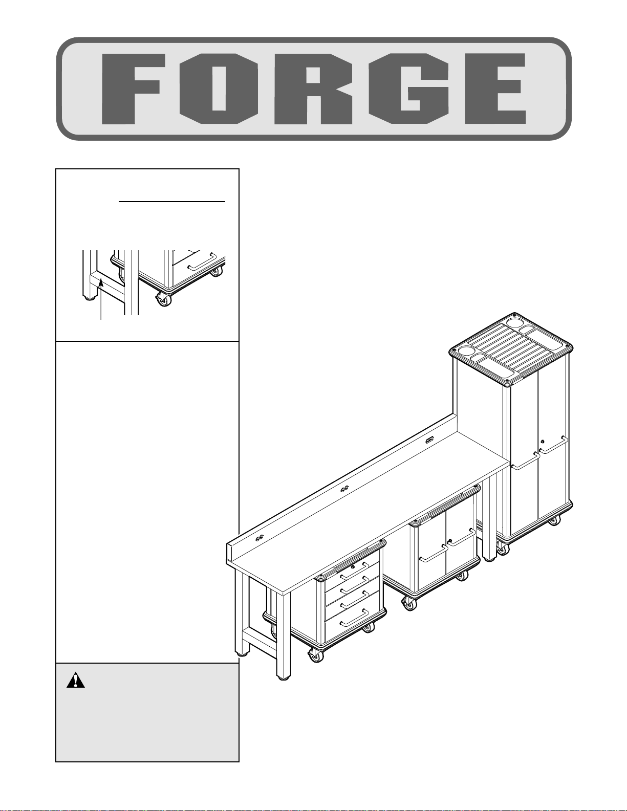
CAUTION
Read all precautions and instructions in this manual before using
this equipment. Save this manual
for future reference.
Model No. FDSS90030
Serial No.
Write the serial number in the
space above for future reference.
QUESTIONS?
As a manufacturer, we are committed to providing complete
customer satisfaction. If you
have questions, or if there are
missing or damaged parts, we
will guarantee complete satisfaction through direct assistance from our factory.
TO AVOID DELAYS, PLEASE
CALL DIRECT TO OUR TOLLFREE CUSTOMER HOT LINE.
The trained technicians on our
customer hot line will provide
immediate assistance, free of
charge.
CUSTOMER HOT LINE:
1-877-660-1666
Mon.–Fri., 6 a.m.–6 p.m. MST
USER’S MANUAL
Serial Number Decal
Page 2

2
IMPORTANT PRECAUTIONS . . . . . . . . . . . . . . . . . . . . . . . . . . . . . . . . . . . . . . . . . . . . . . . . . . . . . . . . . . . . . 3
BEFORE YOU BEGIN . . . . . . . . . . . . . . . . . . . . . . . . . . . . . . . . . . . . . . . . . . . . . . . . . . . . . . . . . . . . . . . . . . . 4
ASSEMBLY . . . . . . . . . . . . . . . . . . . . . . . . . . . . . . . . . . . . . . . . . . . . . . . . . . . . . . . . . . . . . . . . . . . . . . . . . . . 5
USING THE GARAGE ORGANIZER . . . . . . . . . . . . . . . . . . . . . . . . . . . . . . . . . . . . . . . . . . . . . . . . . . . . . . . 17
ORDERING REPLACEMENT PARTS . . . . . . . . . . . . . . . . . . . . . . . . . . . . . . . . . . . . . . . . . . . . . . . .Back Cover
LIMITED WARRANTY . . . . . . . . . . . . . . . . . . . . . . . . . . . . . . . . . . . . . . . . . . . . . . . . . . . . . . . . . . . Back Cover
Note: APART IDENTIFICATION CHART, a PART LIST, and an EXPLODED DRAWING are attached in the center of this manual. Remove the PART IDENTIFICATION CHART, PART LIST, and EXPLODED DRAWING before
beginning assembly.
TABLE OF CONTENTS
Page 3

3
1. Read all instructions in this manual before
using the garage organizer.
2. Use the garage organizer only as described
in this manual.
3. It is the responsibility of the owner to make
sure that all users of the garage organizer are
adequately informed of all precautions.
4. Do not use the garage organizer as a ladder
or a step stool.
5. Regularly inspect and tighten all parts of the
garage organizer. Replace any worn parts
immediately.
6. Do not allow children to play on the garage
organizer; do not allow them to move or ride
on the short or tall two-door locker or the
drawer cabinet.
7. When the short and tall two-door lockers
and the drawer cabinet are in the desired
positions, lock the front casters.
8. The work bench is designed to support a
maximum weight of 1,000 pounds. The short
and tall two-door lockers are designed to
support a maximum weight of 300 pounds;
each shelf is designed to support a maximum
weight of 50 pounds. The drawer cabinet is
designed to support a maximum weight of
300 pounds; each drawer is designed to support a maximum weight of 65 pounds. Always
distribute weight as evenly as possible on
the table top, the cabinet tops, the shelves,
and the drawers.
9. Load the short and tall two-door lockers and
the drawer cabinet with the heaviest objects
at the bottom. Remove heavy objects from
the tops of the short and tall two-door lockers and the drawer cabinet before unloading
the bottoms.
10. The work bench is equipped with a Ground
Fault Circuit Interrupter (GFCI) on the backsplash. The GFCI must be tested before the
outlets on the backsplash are used (see
TESTING THE GFCI OUTLET on page 17).
WARNING: To reduce the risk of serious injury, read the following important precautions
before using the garage organizer.
IMPORTANT PRECAUTIONS
WARNING:
Read all instructions before using the garage organizer. ICON assumes no
responsibility for personal injury or property damage sustained by or through the use of this product.
Page 4
4
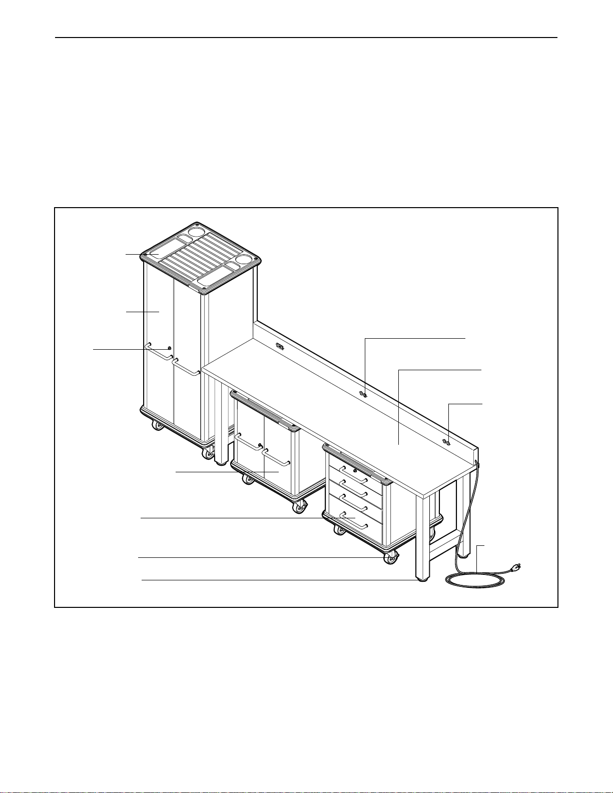
Locking Caster
Tall TwoDoor Locker
Lock
Short Two-Door Locker
Adjustable Foot
Work Bench
Power Cord
Drawer Cabinet
Cabinet Top
Standard Outlet
GFCI Outlet
BEFORE YOU BEGIN
Thank you for selecting the versatile FORGE garage
organizer. The FORGE garage organizer offers a
selection of features designed to organize and
enhance your workspace.
For your benefit, read this manual carefully before
using the garage organizer. If you have questions
after reading this manual, please call our Customer
Service Department toll-free at 1-877-660-1666,
Monday through Friday, 6 a.m. until 6 p.m. Mountain
Time (excluding holidays). To help us assist you,
please mention the product model number and serial
number when calling. The model number is
FDSS90030. The serial number can be found on a
decal attached to the work bench (see the front cover of
this manual for the location of the decal).
Before reading further, please examine the drawing
below and familiarize yourself with the parts that are
labeled.
Page 5
5
Before beginning assembly, carefully read the
following information and instructions:
• Assembly requires two persons.
• Assembly is divided into four stages: (1) short
two-door locker assembly, (2) tall two-door locker
assembly, (3) drawer cabinet assembly, and
(4) work bench assembly.
• Place all parts in a cleared area and remove the
packing materials. Do not dispose of the packing
materials until assembly is completed. Do not
remove the table top from the box until
instructed to do so.
• For help identifying small parts, use the
PART IDENTIFICATION CHART in the center
of this manual. Note: Some small parts may
have been preattached for shipping. If a part is
not in the part bags, check to see if it has been
pre-attached.
• Tighten all parts as you assemble them, unless
instructed to do otherwise.
• As you assemble the garage organizer, make
sure all parts are oriented exactly as shown in
the drawings.
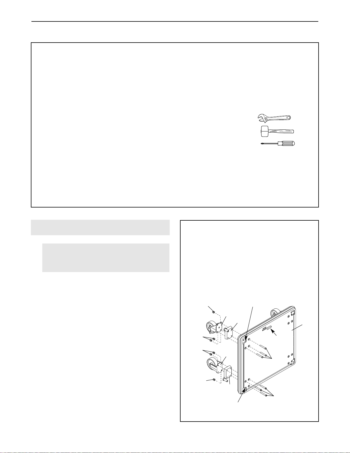
Assembly requires the included Allen wrenches
and the following tools (not included):
• One adjustable wrench
• One rubber mallet
• One Phillips screwdriver
Assembly will be more convenient if you have a
socket set, a set of open-end or closed-end
wrenches, or a set of ratchet wrenches. Apair of
pliers is also recommended.
ASSEMBLY
1
Door
Stop
Do not put a bolt
in this hole
Do not put a bolt
in this hole
50
50
57
57
22
21
20
19
50
50
1.
Have a second person hold a Cabinet Base (1) in
the position shown, with the door stop at the top.
Insert a Right-Tab Insert (22) into the indicated
corner of the Cabinet Base. Attach a Locking
Caster (19) and the Right-Tab Insert to the
Cabinet Base with three 5/16” x 2 1/4” Button
Head Bolts (57) and three 5/16” Nylon Locknuts
(50).
Attach a Left-Tab Insert (21) and a Non-Locking
Caster (20) to the indicated corner of the Cabinet
Base (1) in the same manner.
Repeat this step on the left side of the Cabinet
Base (1).
Short Two-Door Locker
DO NOT ATTEMPT TO ASSEMBLE THE
GARAGE ORGANIZER WITHOUT CAREFULLY
READING EACH ASSEMBL Y STEP.
For easy part identification, remove the PART
IDENTIFICATION CHART from the center of
this manual and lay it on the floor.
1
Before beginning, read the important
assembly information at the top of this
page and at the right.
Page 6
6
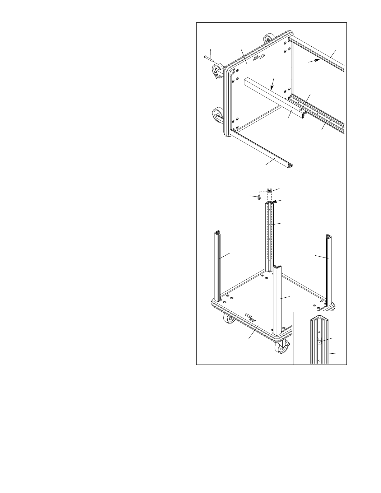
3. Set the Cabinet Base (1) in the position shown.
Insert a Shelf Bracket (31) into the indicated slot
in one of the Short Rear Posts (3) (see the inset
drawing). Secure the Shelf Bracket at the desired
height with a 1/4” x 1 1/2” Cap Screw (56). Insert
a Shelf Bracket into each of the three remaining
Posts (3, 4, and 5). Secure each Shelf Bracket
with a 1/4” x 1 1/2” Cap Screw. Make sure all
four Shelf Brackets are at the same height.
2. Identify a Short Front Right Post (5) and a Short
Front Left Post (4); each of these Posts has a lip
on one side and is labeled with a sticker.
Attach the Short Front Right Post (5) to the
Cabinet Base (1) with a 5/16” x 2 1/4” Button
Head Bolt (57). Attach the Short Front Left Post
(4) and two Short Rear Posts (3) to the Cabinet
Base in the same manner.
1
57
5
3
3
3
3
5
4
1
31
Slot
56
4
Lip
Lip
3
2
31
3
Sticker
Page 7
7
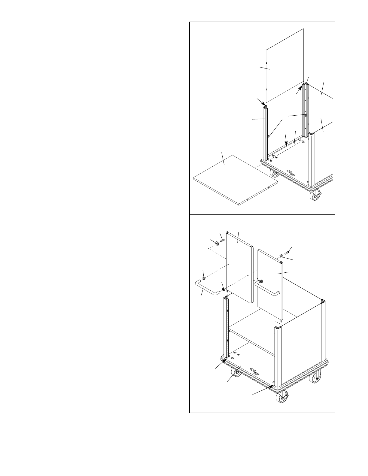
4. Set a Shelf (17) on the four Shelf Brackets (31).
Slide a Short Side Panel (13) into the indicated
slots in the Short Front Left Post (4) and the left
Short Rear Post (3). Make sure the Short Side
Panel is in the indicated slot in the Cabinet Base
(1). Insert another Short Side Panel and a Short
Rear Panel (14) in the same manner.
4
5. Attach a Handle (18) to the Short Left Cabinet
Door (9) with two 1/4” x 5/8” Button Head Screws
(63), two 1/4” Washers (62), and two Handle
Trims (25) as shown. Attach a Handle to the Short
Right Cabinet Door (10) in the same manner.
Insert the Short Left Cabinet Door (9) into the left
hinge rod hole in the Cabinet Base (1). Insert the
Short Right Cabinet Door (10) into the right hinge
rod hole in the Cabinet Base. Have a second person hold both Cabinet Doors in place.
5
13
4
1
3
13
31
Slot
Slot
Slot
17
10
Hinge
Rod
Hole
Hinge
Rod
Hole
9
18
1
25
62
62
63
63
25
14
Page 8
8
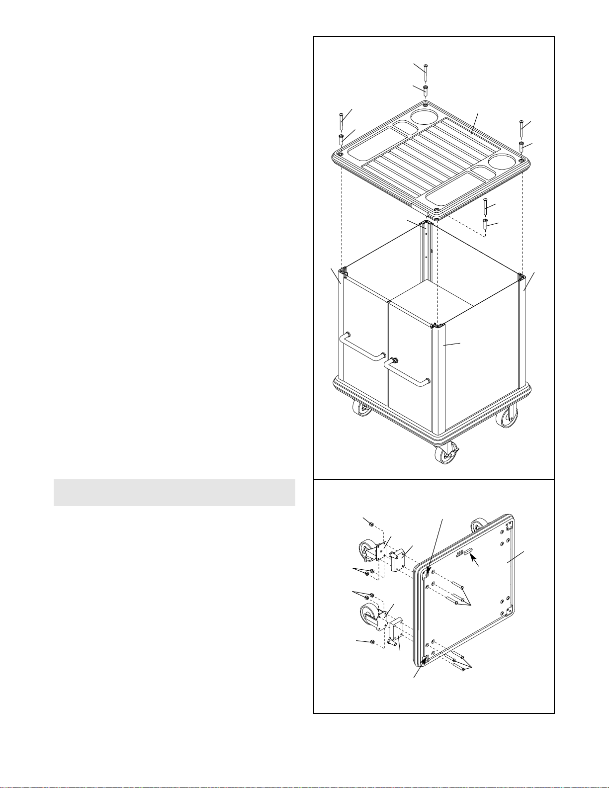
6. Attach a Cabinet Top (2) to the four Posts (3, 4,
and 5) with four 5/16” x 2 1/4” Button Head Bolts
(57) and four Spacer Inserts (26).
7. Have a second person hold a Cabinet Base (1) in
the position shown, with the door stop at the top.
Insert a Right-Tab Insert (22) into the indicated
corner of the Cabinet Base. Attach a Locking
Caster (19) and the Right-Tab Insert to the
Cabinet Base with three 5/16” x 2 1/4” Button
Head Bolts (57) and three 5/16” Nylon Locknuts
(50).
Attach a Left-Tab Insert (21) and a Non-Locking
Caster (20) to the indicated corner of the Cabinet
Base (1) in the same manner.
Repeat this step on the left side of the Cabinet
Base (1).
6
Tall Two-Door Locker
2
57
57
26
26
26
3
3
4
5
26
57
57
1
50
50
57
57
22
21
20
19
50
50
7
Door
Stop
Do not put a bolt
in this hole
Do not put a bolt
in this hole
Page 9

9
8. Identify the two Tall Front Posts (7); each of these
Posts has a lip on one side.
Attach one of the Tall Front Posts (7) to the
Cabinet Base (1) with a 5/16” x 2 1/4” Button
Head Bolt (57). Attach the other Tall Front Post
and the two Tall Rear Posts (6) to the Cabinet
Base in the same manner.
9. Lift the Cabinet Base (1) to the position shown.
With the help of a second person, lift one side of
the table top (not shown) and remove the two Tall
Side Panels (15) and the Tall Rear Panel (16)
from beneath the Table Top. Do not remove the
table top from the box until instructed to do
so.
Slide one of the Tall Side Panels (15) into the
indicated slots in one of the Tall Front Posts (7)
and one of the Tall Rear Posts (6). Insert the
other Tall Side Panel and the Tall Rear Panel (16)
in the same manner.
Stretch the large elastic band around the Posts
(7 and 6) as shown; the elastic band will hold the
Posts in position until step 12 is completed.
8
9
57
Lip
Lip
7
7
6
1
6
15
15
Slot
Slot
Elastic
Band
16
7
1
6
Page 10

10
10. Insert three Shelf Brackets (31) into the indicated
slot in one of the Tall Rear Posts (6). Secure the
Shelf Brackets at the desired heights with three
1/4” x 1 1/2” Cap Screws (56). Insert three Shelf
Brackets into each of the other three Tall Posts.
Secure the Shelf Brackets with 1/4” x 1 1/2” Cap
Screws. Make sure the lowest four Shelf
Brackets are at the same height, the middle
four Shelf Brackets are at the same height,
and the highest four Shelf Brackets are at the
same height.
11. Set a Shelf (17) on each set of Shelf Brackets
(31).
10
11
31
56
6
7
17
31
31
31
17
17
7
6
Slot
Page 11

11
13. See the inset drawing. Attach a Handle (18) to
the Tall Left Cabinet Door (11) with two 1/4” x 5/8”
Button Head Bolts (63), two 1/4” Washers (62),
and two Handle Trims (25) as shown. Attach a
Handle to the Tall Right Cabinet Door (12) in the
same manner.
Insert the Tall Left Cabinet Door (11) into the left
hinge rod hole (not shown) in the Cabinet Base
(1). Insert the Tall Right Cabinet Door (12) into
the right hinge rod hole in the Cabinet Base. Lift
the Cabinet Top (2), and insert the Cabinet Doors
into the hinge rod holes in the Cabinet Top.
Tighten the four 5/16” x 2 1/4” Button Head Bolts
(57).
12. Set a Cabinet Top (2) on the four Posts (7 and 6).
Thread four 5/16” x 2 1/4” Button Head Bolts (57)
with four Spacer Inserts (26) two complete turns
into the Cabinet Top and the Posts; do not tighten
the Button Head Bolts yet.
Remove the elastic band (not shown) from the
Posts (6 and 7).
13
12
11
12
7
2
57
57
57
1
11
18
25
25
63
63
62
62
7
57
57
57
26
26
26
6
6
7
7
57
26
2
Hinge
Rod
Holes
Page 12

12
14. Have a second person hold a Cabinet Base (1) in
the position shown. Insert a Right-Tab Insert (22)
into the indicated corner of the Cabinet Base.
Attach a Locking Caster (19) and the Right-Tab
Insert to the Cabinet Base with three 5/16” x
2 1/4” Button Head Bolts (57) and three 5/16”
Nylon Locknuts (50).
Attach a Left-Tab Insert (21) and a Non-Locking
Caster (20) to the indicated corner of the Cabinet
Base (1) in the same manner.
Repeat this step on the left side of the Cabinet
Base (1).
16. Have another person hold a Drawer Left Side
Panel (35) and a Drawer Right Side Panel (36) in
the positions shown. Align the flanges on the
edges of a Drawer Rear Panel (34) with the indicated flanges on the Side Panels, and slide the
Drawer Rear Panel down into the flanges on the
Side Panels.
Align the flanges on the edges of a Drawer Bottom
(33) with the indicated flanges on the Side Panels
(35, 36). Slide the Drawer Bottom into the flanges
on the Side Panels. Make sure the three tabs
on the Drawer Bottom slide onto the indicated
lip on the Drawer Rear Panel (34).
Repeat this step for the other three drawers.
15. Identify the Right Post Assembly (A), which has
the Door Lock Bracket (29) attached to it. Orient
the Right Post Assembly as shown, and attach it
to the Cabinet Base (1) with two 5/16” x 2 1/4”
Button Head Bolts (57).
Attach the Left Post Assembly (B) to the
Cabinet Base (1) in the same manner.
Set the Cabinet Base (1) on the casters.
See the inset drawing. Attach the Drawer Lock
Spring (30) to the Drawer Lock Pivot (29) and the
indicated Drawer Lock Bracket (28).
Drawer Cabinet
15
57
57
29
29
A
B
1
1
Door
Stop
50
50
57
57
22
21
20
19
50
50
14
Do not put a bolt
in this hole
Do not put a bolt
in this hole
34
35
36
33
Tabs
Flanges
Flanges
Flange
Flanges
Lip
16
30
28
Page 13

13
18. Attach the Small Drawer Front Panel (37) to the
tabs on the Side Panels (35, 36) of one of the
drawers with two #10 x 3/8” Machine Bolts (53)
and two #10 Nylon Locknuts (65).
Attach a Handle (18) and the Locking Drawer
Face (8) to the Small Drawer Front Panel (37)
with two 1/4” x 1 3/16” Machine Screws (54), two
Bushings (66), and two Handle Trims (25) as
shown.
Repeat this step for the other three drawers.
Note: Two of the drawers will have Small Drawer
Faces (39, not shown) and one drawer will have
a Large Drawer Face (40, not shown).
17. See drawing 17a. Orient a Small Drawer Front
Panel (37) at an angle as shown. Hold the Small
Drawer Front Panel under the indicated tabs on
the Side Panels (35, 36) of one of the drawers.
See drawing 17b. (Note: This drawing shows
the drawer from the back.) Press the indicated
tabs on the Small Drawer Front Panel (37) onto
the indicated lip on the Drawer Bottom (33). Make
sure the Small Drawer Front Panel is behind
the tabs on the Side Panels (35, 36).
Repeat this step for the other three drawers.
Note: One of the drawers will have a Large
Drawer Front Panel (38, not shown) instead of a
Small Drawer Front Panel (37).
17a
18
17b
37
35
36
37
36
35
33
54
53
53
36
35
37
65
66
66
65
8
25
25
18
Tab
Tab
Tabs
Lip
Tab
Tab
View from the back
Page 14

14
19. Slide a Short Side Panel (13) into the indicated
slots in the Left Post Assembly (B). Insert another
Short Side Panel and a Short Rear Panel (14) in
the same manner.
B
13
13
14
Slots
20
19
B
A
2
57
26
57
26
57
26
57
26
20. Attach the remaining Cabinet Top (2) to the Post
Assemblies (A, B) with four 5/16” x 2 1/4” Button
Head Bolts (57) and four Spacer Inserts (26).
Page 15

15
21
41
8
41
Large
Drawer
21. Insert the drawer with the Locking Drawer Face
(8) into the top two Drawer Slides (41).
Insert the remaining three drawers in the
same manner. Make sure the large drawer is
at the bottom.
22. Note: Do not remove the Table Top (46) from
the box yet.
Orient one of the Table Legs (45) as shown, so
the indicated slot is toward the back of the Table
Top (46) (there are holes along the back edge of
the Table Top). Make sure two Adjustable Feet
(49) are fully threaded into the Table Leg.
Attach the Table Leg (45) to the Table Top (46)
with eight 1/4” x 1 3/16” Lag Screws (60). Do not
tighten the Lag Screws yet.
Repeat this step with the other Table Leg (not
shown).
22
Work Bench
49
45
46
60
60
60
60
Slot
Back
Hole
Front
49
Page 16

16
23. With the help of a second person, remove the
Table Top (46) from the box and stand it on the
Table Legs (45).
Have a second person hold the Table Brace (47)
against the Table Legs (45) and the Table Top
(46). Attach the Table Brace to the indicated Table
Leg with two 5/16” x 3/4” Hex Head Screws (61)
and two 5/16” Star Washers (58). Do not tighten
the Hex Head Screws yet. Attach the Table
Brace to the other Table Leg in the same manner.
24. Attach the Backsplash (48) to the Table Top (46)
and the Table Brace (47) with five 1/4” x 2” Hex
Head Screws (59) and five 1/4” Star Washers
(51) as shown.
See step 22 and tighten the 1/4” x 1 3/16” Lag
Screws (60). See step 23 and tighten the 5/16” x
3/4” Hex Head Screws (61).
25. Make sure all parts of the garage organizer
are properly tightened. Note: Some hardware
may be left over after assembly is completed.
24
47
45
46
59
59
59
59
46
48
47
59
51
51
51
58
58
61
23
Page 17

17
USING THE GARAGE ORGANIZER
PLUGGING IN THE POWER CORD
This product must be grounded. If it should malfunc-
tion or break down, grounding provides a path of least
resistance for electric current to reduce the risk of
electric shock. This product is equipped with a cord
having an equipment-grounding conductor and a
grounding plug.
This product is for use on a nominal 120-volt circuit,
and has a grounding plug that looks like the plug illustrated in drawing 1 below.
A temporary adapter that looks like the adapter illustrated in drawing 2 may be used to connect the
grounding plug to a 2-pole receptacle if a properly
grounded outlet is not available.
The temporary adapter should be used only until a
properly grounded outlet (see drawing 1) can be
installed by a qualified electrician.
The green-colored rigid ear, lug, or the like extending
from the adapter (see drawing 2) must be connected
to a permanent ground such as a properly grounded
outlet box cover. Whenever the adapter is used, it
must be held in place by a metal screw. Some 2-pole
receptacle outlet box covers are not grounded.
Contact a qualified electrician to determine if the
outlet box cover is grounded before using an
adapter.
TESTING THE GFCI OUTLET
The work bench
has a Ground
Fault Circuit
Interrupter
(GFCI) outlet on
the backsplash.
The GFCI outlet
has a test button and a reset
button. To test
the GFCI outlet,
plug a radio into
the outlet and
push the test
button. The radio should shut off. Press the reset button. The radio should turn on again. If the radio does
not shut off when the test button is pressed, the GFCI
is damaged. Do not use the outlets on the work bench
until the GFCI has been repaired or replaced by a
qualified electrician.
LEVELING THE WORK BENCH
If the work
bench is not
level when it is
placed in the
desired location,
turn one or
more of the
adjustable feet
until the work
bench is level.
Make sure the
work bench is
resting on all
four adjustable
feet.
DANGER:Improper connection
of the equipment-grounding conductor can
result in an increased risk of electric shock.
Check with a qualified electrician or serviceman if you are in doubt as to whether the
product is properly grounded. Do not modify
the plug provided with the product—if it will
not fit the outlet, have a proper outlet
installed by a qualified electrician.
2
Grounded Outlet Box
Grounding Plug
Adapter
Lug
Metal Screw
1
Grounded Outlet Box
Grounding Plug
Grounding Pin
Grounded Outlet
Test
GFCI
Outlet
Reset
Adjustable
Foot
Page 18

18
LOCKING THE CASTERS
The locking casters can be locked to prevent the short
and tall two-door lockers and the drawer cabinet from
moving. To lock the casters, press down on the rear
tabs of the levers. To unlock the casters, press down
on the front tabs of the levers.
REMOVING THE DRAWERS
To remove a drawer, first pull the drawer out as far as
it will go. Locate the small lever on the inner drawer
slide on each side of the drawer. Depress the lever on
the right side of the drawer, and lift the lever on the left
side of the drawer. Then, remove the drawer.
Lever
Lever
Inner Drawer Slide
Front Tab
Rear Tab
Lever
Lever
Page 19

19
NOTES
Page 20

REMOVE THIS PART IDENTIFICATION CHART, PART LIST,
AND EXPLODED DRAWING BEFORE BEGINNING ASSEMBLY.
SAVE THIS PART IDENTIFICATION CHART, PART LIST,
AND EXPLODED DRAWING FOR FUTURE REFERENCE.
81
Page 21

PART IDENTIFICATION CHART—Model No. FDSS90030 R1103A
#8 Nylon
Locknut (64)
5/16” Star
Washer (58)
1/4” x 1 3/16”
Machine Screw (54)
1/4” x 2” Hex Head Screw (59)
#10 Nylon Locknut
Machine Bolt
(65)
#8 x 3/8”
(52)
5/16” Nylon
Locknut (50)
#10 x 3/8”
Machine Bolt
(53)
1/4” x 1 1/2” Cap
Screw (56)
5/16” x 3/4” Hex
Head Screw (61)
1/4” Star
Washer (51)
1/4” x 1/2” Cap
Screw (55)
5/16” x 2 1/4” Button
Head Bolt (57)
1/4” Washer (62)
1/4” x 5/8”
Button Head
Screw (63)
1/4” x 1 3/16”
Lag Screw (60)
Page 22

Key No. Qty. Description Key No. Qty. Description
1 3 Cabinet Base
2 3 Cabinet Top
3 4 Short Rear Post
4 2 Short Front Left Post
5 2 Short Front Right Post
6 2 Tall Rear Post
7 2 Tall Front Post
8 1 Locking Drawer Face
9 1 Short Left Cabinet Door
10 1 Short Right Cabinet Door
11 1 Tall Left Cabinet Door
12 1 Tall Right Cabinet Door
13 4 Short Side Panel
14 2 Short Rear Panel
15 2 Tall Side Panel
16 1 Tall Rear Panel
17 4 Shelf
18 8 Handle
19 6 Locking Caster
20 6 Non-Locking Caster
21 6 Left-Tab Insert
22 6 Right-Tab Insert
23 2 Short Hinge Rod
24 2 Tall Hinge Rod
25 16 Handle Trim
26 12 Spacer Insert
27 8 Drawer Slide Bracket
28 2 Drawer Lock Pivot
29 1 Drawer Lock Bracket
30 1 Drawer Lock Spring
31 16 Shelf Bracket
32 8 Hinge Retainer Ring
33 4 Drawer Bottom
34 4 Drawer Rear Panel
35 4 Drawer Left Side Panel
36 4 Drawer Right Side Panel
37 3 Small Drawer Front Panel
38 1 Large Drawer Front Panel
39 2 Small Drawer Face
40 1 Large Drawer Face
41 8 Drawer Slide
42 3 Lock Assembly
43 1 Short Cabinet Cam
44 1 Tall Cabinet Cam
45 2 Table Leg
46 1 Table Top
47 1 Table Brace
48 1 Backsplash
49 4 Adjustable Foot
50 48 5/16” Nylon Locknut
51 5 1/4” Star Washer
52 32 #8 x 3/8” Machine Bolt
53 8 #10 x 3/8” Machine Bolt
54 8 1/4” x 1 3/16” Machine Screw
55 18 1/4” x 1/2” Cap Screw
56 16 1/4” x 1 1/2” Cap Screw
57 72 5/16” x 2 1/4” Button Head Bolt
58 4 5/16” Star Washer
59 5 1/4” x 2” Hex Head Screw
60 16 1/4” x 1 3/16” Lag Screw
61 4 5/16” x 3/4” Hex Head Screw
62 8 1/4” Washer
63 8 1/4” x 5/8” Button Head Screw
64 32 #8 Nylon Locknut
65 8 #10 Nylon Locknut
66 16 Bushing
67 1 Drawer Cabinet Cam
# 1 User’s Manual
# 1 Elastic Band
# 1 5/32” Hex Key
# 1 3/16”–5/32” Hex Key
PART LIST—Model No. FDSS90030 R01103A
Note: “#” indicates a non-illustrated part. Specifications are subject to change without notice. See the back cover
of the user’s manual for information about ordering replacement parts.
Page 23

EXPLODED DRAWING—Model No. FDSS90030 R1103A
57
50
20
22
50
19
57
50
50
19
57
50
50
50
50
32
313131
565656
57
31
31
56
56
313131
26
31
56
56
56
31
31
31
6
56
56
32
57
26
24
6
7
7
57
57
57
57
1
57
66
66
44
21
57
20
22
21
63
62
12
26
57
66
2
26
57
32
66
16
17
24
17
11
63
62
15
61
58
51
51
51
59
59
63
62
63
62
25
59
60
25
42
25
18
25
18
60
32
60
45
60
49
47
4846
61
58
51
51
60
59
59
60
60
45
60
49
49
49
Page 24

EXPLODED DRAWING—Model No. FDSS90030 R1103A
36
52
64
64
41
52
34
33
35
52
64
52
64
26
57
53
64
41
52
64
52
26
57
2
26
57
52
53
65
54
66
67
54
66
65
28
42
8
25
29
55
26
57
34
64
64
52
33
35
37
64
52
64
52
25
18
55
53
41
52
64
64
52
30
28
27
27
55
55
55
55
55
27
27
52
36
53
54
66
65
55
27
55
55
55
55
27
27
64
64
41
52
52
65
54
66
39
25
27
55
55
55
55
34
64
64
52
33
35
37
52
64
52
25
18
57
3
4
53
64
41
52
64
64
52
3
57
5
57
1
57
52
36
53
54
66
65
57
64
64
41
52
52
65
54
66
39
25
34
64
64
52
33
35
37
52
64
52
25
18
22
53
64
41
52
64
64
52
21
50
57
20
21
52
36
54
66
65
50
57
20
22
57
64
64
41
52
52
64
64
53
54
50
52
65
38
66
25
40
18
25
50
19
57
50
19
50
13
17
14
26
57
26
57
57
26
2
57
32
66
26
23
66
63
62
31
56
31
31
56
56
3
56
31
63
62
25
25
18
3
57
5
57
4
32
9
32
57
57
1
57
23
66
66
63
63
62
57
22
21
43
62
63
25
50
57
21
20
50
22
20
57
62
25
42
18
50
19
57
50
32
10
50
19
50
Page 25

Part No. 204403 R1103A Printed in USA © 2003 ICON Health & Fitness, Inc.
To order replacement parts, call our Customer Service Department toll-free at 1-877-660-1666, Monday through
Friday, 6 a.m. until 6 p.m. MST (excluding holidays). Please be prepared to give the following information:
• The MODEL NUMBER of the product (FDSS90030)
• The NAME of the product (FORGE garage organizer)
• The SERIAL NUMBER of the product (see the front cover of this manual)
• The KEY NUMBER and DESCRIPTION of the part(s) (see the PART LIST and EXPLODED DRAWING in the
center of this manual)
ORDERING REPLACEMENT PARTS
LIMITED WARRANTY
ICON Health & Fitness, Inc. (ICON), warrants this product to be free from defects in workmanship and
material, under normal use and service conditions, for a period of ninety (90) days from the date of purchase. This warranty extends only to the original purchaser. ICON's obligation under this warranty is limited to replacing or repairing, at ICON's option, the product through one of its authorized service centers.
All repairs for which warranty claims are made must be pre-authorized by ICON. This warranty does not
extend to any product or damage to a product caused by or attributable to freight damage, abuse, misuse, improper or abnormal usage or repairs not provided by an ICON authorized service center; products
used for commercial or rental purposes; or products used as store display models. No other warranty
beyond that specifically set forth above is authorized by ICON.
ICON is not responsible or liable for indirect, special or consequential damages arising out of or in connection with the use or performance of the product or damages with respect to any economic loss, loss
of property, loss of revenues or profits, loss of enjoyment or use, costs of removal or installation or other
consequential damages of whatsoever nature. Some states do not allow the exclusion or limitation of incidental or consequential damages. Accordingly, the above limitation may not apply to you.
The warranty extended hereunder is in lieu of any and all other warranties and any implied warranties of
merchantability or fitness for a particular purpose is limited in its scope and duration to the terms set forth
herein. Some states do not allow limitations on how long an implied warranty lasts. Accordingly, the above
limitation may not apply to you.
This warranty gives you specific legal rights. You may also have other rights which vary from state to state.
ICON HEALTH & FITNESS, INC., 1500 S. 1000 W., LOGAN, UT 84321-9813
 Loading...