

Page 1
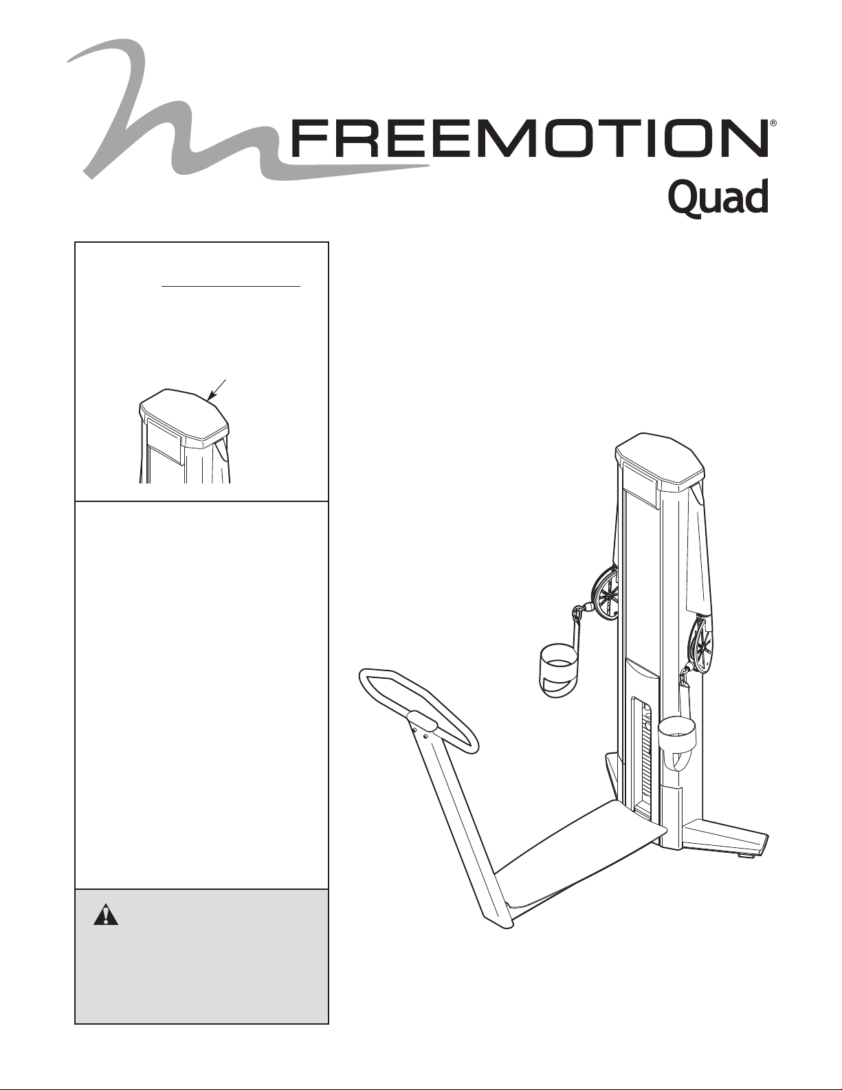
Model No. F609.1
Serial No.
Write the serial number in the
space above for reference.
Serial Number Decal
(inside tower)
QUESTIONS?
If you have questions, or if parts
are damaged or missing, please
see HOW TO CONTACT
CUSTOMER CARE on the back
cover of this manual.
OWNERʼS MANUAL
CAUTION
Read all precautions and instructions in this manual before using
this equipment. Keep this manual
for future reference.
www.freemotionfitness.com
Page 2

TABLE OF CONTENTS
MPORTANT PRECAUTIONS . . . . . . . . . . . . . . . . . . . . . . . . . . . . . . . . . . . . . . . . . . . . . . . . . . . . . . . . . . . . . . . .3
I
WARNING DECAL PLACEMENT . . . . . . . . . . . . . . . . . . . . . . . . . . . . . . . . . . . . . . . . . . . . . . . . . . . . . . . . . . . . . .4
BEFORE YOU BEGIN . . . . . . . . . . . . . . . . . . . . . . . . . . . . . . . . . . . . . . . . . . . . . . . . . . . . . . . . . . . . . . . . . . . . . .5
ADJUSTMENT . . . . . . . . . . . . . . . . . . . . . . . . . . . . . . . . . . . . . . . . . . . . . . . . . . . . . . . . . . . . . . . . . . . . . . . . . . . .6
MAINTENANCE AND TROUBLESHOOTING . . . . . . . . . . . . . . . . . . . . . . . . . . . . . . . . . . . . . . . . . . . . . . . . . . . .7
ABLE DIAGRAM . . . . . . . . . . . . . . . . . . . . . . . . . . . . . . . . . . . . . . . . . . . . . . . . . . . . . . . . . . . . . . . . . . . . . . . . .11
C
PART LIST . . . . . . . . . . . . . . . . . . . . . . . . . . . . . . . . . . . . . . . . . . . . . . . . . . . . . . . . . . . . . . . . . . . . . . . . . . . . . .13
EXPLODED DRAWING . . . . . . . . . . . . . . . . . . . . . . . . . . . . . . . . . . . . . . . . . . . . . . . . . . . . . . . . . . . . . . . . . . . .14
HOW TO CONTACT CUSTOMER CARE . . . . . . . . . . . . . . . . . . . . . . . . . . . . . . . . . . . . . . . . . . . . . . .Back Cover
FREEMOTION is a registered trademark of ICON IP, Inc.
2
Page 3

IMPORTANT PRECAUTIONS
WARNING: To reduce the risk of serious injury, read all important precautions and
nstructions in this manual and all warnings on your strength equipment before using your strength
i
equipment. FreeMotion Fitness assumes no responsibility for personal injury or property damage
sustained by or through the use of this product.
1. Before beginning any exercise program,
consult your physician. This is especially
important for persons over age 35 or persons with pre-existing health problems.
2. Use the strength equipment only as
described in this manual.
3. It is the purchaserʼs responsibility to ensure
that there is enough space around the
strength equipment for the intended exercise. Do not crowd the strength equipment.
4. Using the two 9/16" anchor holes in the
base of the tower to provide maximum stability, the strength equipment must be
anchored to the floor where required or
whenever possible.
5. Use the strength equipment only on a level
surface. Cover the floor beneath the
strength equipment to protect the floor.
6. It is the responsibility of the owner to
ensure that all users of the strength equipment are adequately informed of all
precautions, have read and understood all
warning and caution labels, and are
informed of how to use the strength equipment properly.
7. Keep children under age 12 and pets away
from the strength equipment at all times.
8. Keep hands and feet away from moving
parts. Do not lean on or rest your hands on
the strength equipment when it is in use.
9. Always wear athletic shoes for foot protection while exercising.
10. All users of the strength equipment should
be instructed to report any injury or
strength equipment irregularity to facility
staff immediately.
11. Make sure the weight pin is completely
inserted into one of the weight plates.
12. Make sure the handles are attached securely
before each use of the strength equipment.
13. Check all cables, cable connections, and
pulleys before each use of the strength
equipment. Make sure all parts are properly
tightened. Replace any worn parts immediately.
14. Make sure the cable remains on the pulleys
at all times. If the cable binds while you are
exercising, stop immediately and make sure
the cable is on the pulleys and nothing is
interfering with the cable or pulleys.
15. The strength equipment is designed to support a maximum user weight of 350 lbs.
(159 kg).
16. Over exercising may result in serious injury
or death. If you feel faint or if you experience pain while exercising, stop
immediately and cool down.
3
Page 4
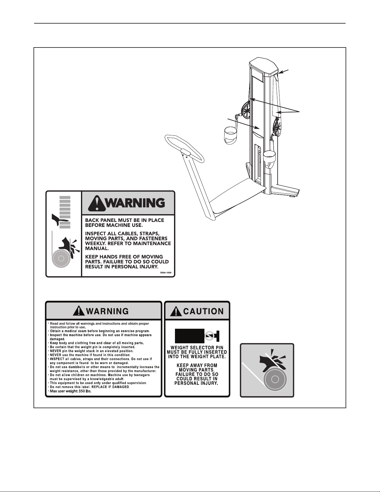
WARNING DECAL PLACEMENT
This drawing shows the location(s) of the
warning decal(s). If a decal is missing
or illegible, see the back cover of this
manual and request a free replacement
decal. Apply the decal in the location
shown. Note: The decal(s) may not be
shown at actual size.
Decal 1
Decal 1 (inside
access cover)
Decal 3
Decal 2
Decal 2 (This decal is part of the instruction placard)
Decal 3
4
Page 5
BEFORE YOU BEGIN
Thank you for selecting the FREEMOTION®QUAD
strength equipment. With unrestricted motion, you can
work your bodyʼs muscle groups together—the same
ay you do naturally—and train more specifically and
w
efficiently.
For your benefit, read this manual carefully before
using the strength equipment. If you have questions
after reading this manual, please see the back cover
Assembled Dimensions:
Height: 6 ft. 2 in. (188 cm)
Width: 3 ft. (91 cm)
Depth: 5 ft. 6 in. (168 cm)
of this manual. To help us assist you, note the product
model number and serial number before contacting us.
The model number the location of the serial number
ecal are shown on the front cover of this manual.
d
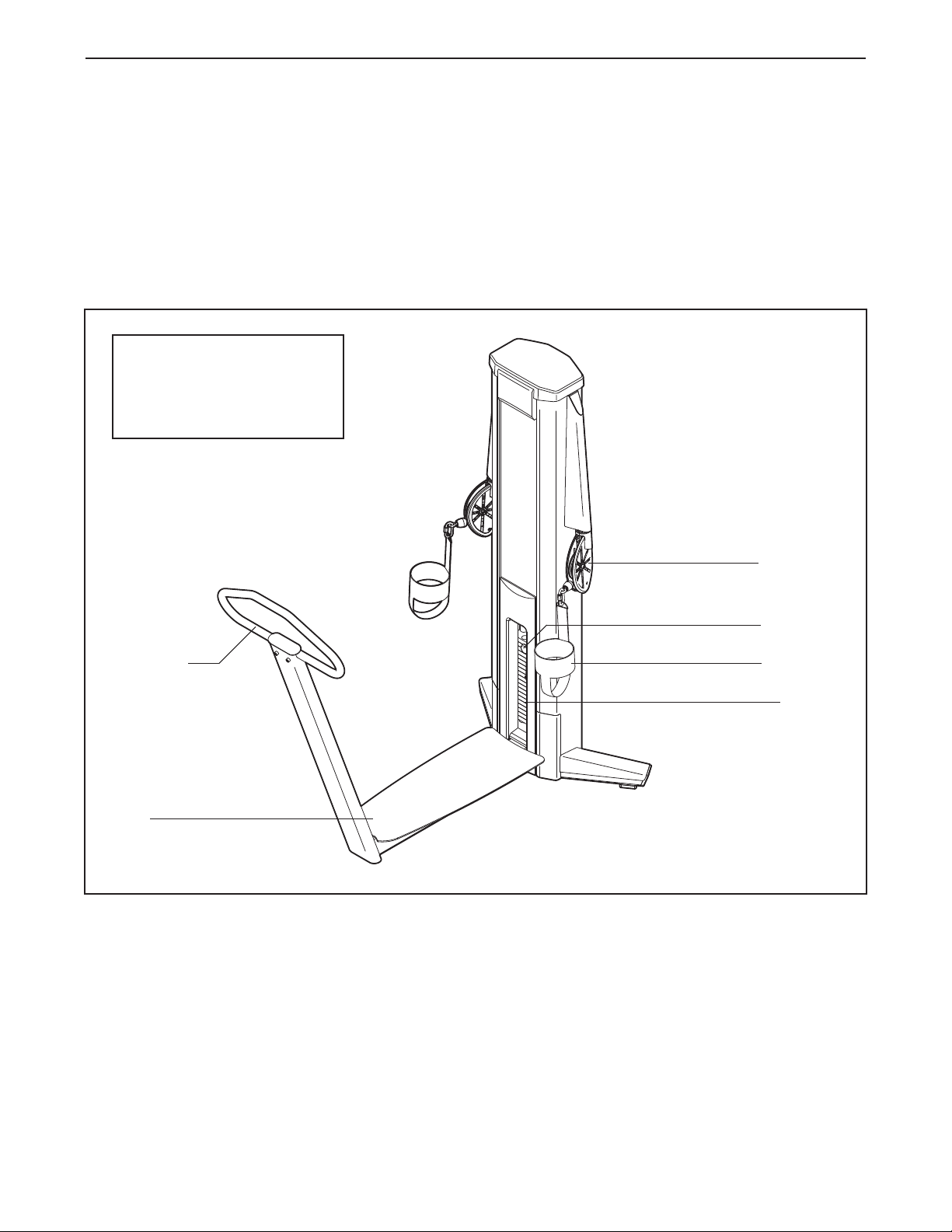
efore reading further, please review the drawing
B
below and familiarize yourself with the parts that are
labeled.
Swivel Arm
Handlebar
Deck
Weight Pin
Foot Strap
Weights
5
Page 6

ADJUSTMENT
his section explains how to adjust the strength equipment. Make sure all parts are properly tightened each time
T
the strength equipment is used. Replace any worn parts immediately.
ADJUSTING THE RESISTANCE
To change the amount of resistance for your workout, insert the weight pin into the desired weight.
Make sure that the weight pin is fully inserted into
the weight stack.
Weight Pin
Weight Stack
6
Page 7

MAINTENANCE AND TROUBLESHOOTING
For optimal performance of the strength equipment and to reduce the chances of injury to users, you must perform preventive maintenance on a regular basis. Instruct all personnel to perform the procedures described in
his section. Personnel must also record and report any accident. To maintain the strength equipmentʼs warranty,
t
use only FREEMOTION parts for repair or replacement. If there are any questions or concerns, see HOW TO
CONTACT CUSTOMER CARE on the back cover of this manual.
DAILY MAINTENANCE
Upholstery and Frame—General Cleaning
1. Clean the strength equipment using a soft cloth
dampened with a light solution of mild soap and
warm water. If necessary, use a soft bristle brush
with the cleaning solution.
2. Rinse the area thoroughly using a soft cloth dampened with clean water. Dry thoroughly.
Upholstery—Difficult Stains
1. Spray the stain with a non-abrasive household
cleaner such as FORMULA 409
GREEN®, or a similar product. Rub the stained
area gently and let the cleaning solution sit for a
few minutes.
2. Rinse the area thoroughly using a soft cloth dampened with clean water. Dry thoroughly.
3. Repeat these steps if necessary using a soft bristle brush.
Optional Method for Difficult Stains
1. Rub the stained area gently using a soft cloth
dampened with rubbing alcohol.
2. Rinse the area thoroughly using a soft cloth dampened with clean water. Dry thoroughly.
CAUTION: When using any cleaning product, try it
first in an unnoticeable place to ensure that there is no
damage to the material. Follow the directions and the
safety precautions of the manufacturer of each cleaning product used. FreeMotion Fitness and its vendors
cannot be held liable for damage or injuries resulting
from the use or misuse of cleaning products. IMPOR-
TANT: Do not use abrasive cleaners, which may
scratch the strength equipment. Strong cleaners and
abrasives will damage decals; use caution around
decals. Do not use solvents such as lacquer thinner,
kerosene, gasoline, or similar liquids.
®
cleaner, SIMPLE
WEEKLY MAINTENANCE
Hardware
Check all nuts and bolts and tighten them as required.
IMPORTANT: All FREEMOTION cushions have dense
plywood supports with tee-nuts that are used to bolt
the cushions to the strength equipment. Because the
tee-nuts are held by the plywood, they will not withstand the torque that standard nuts and bolts will.
When tightening the bolts securing a cushion, turn
them only until they are snug and the cushion does
not move or feel loose. Overtightening may strip the
tee-nuts from the plywood and make it impossible to
remove the cushion in the future.
Cables
1. Check each cable for proper tension (see CABLE
ADJUSTMENT on page 8).
2. Check the entire length of each cable by slowly
performing one repetition on the strength equipment; inspect the cable that is exposed on the
exterior of the strength equipment and the cable
inside the tower. Run your fingers along the cable,
paying close attention at the bends and attachment points. Watch for the following conditions,
which may indicate a worn cable in need of
replacement:
A. a torn or split cable sheath that exposes the
cable
B. a kinked or severely bent cable
C. a curled or twisted sheath
D. a stretched cable sheath, showing a thinning
cross-section
A
B
C
D
7
Page 8

Cable Traps
Check the cable traps to ensure that they are not rubbing against the cables and that they are holding the
ables in the grooves of the pulleys. If a cable trap is
c
not correctly aligned, loosen the bolt slightly, readjust
he cable trap as necessary, and retighten the bolt.
t
Correct Alignment
Cable
Traps
Pulley
Cable
Traps
If there is too much tension on the cables, the weight
carriage will not rest on the next weight, and it may be
difficult to insert the weight pin into the weights.
If there is not enough tension on the cables, the
eight carriage will not be lifted immediately when the
w
repetition is begun. Ideally, the cable should not move
more than 1/2 in. (1.3 cm) from the resting position
before the weight carriage is lifted.
If there is too much tension or not enough tension on
a cable, adjust the cable as described in the following
steps.
Weight Carriage Pulley Adjustment
Tools required: 5/16" hex key, 9/16" open end wrench
Rubbing
Incorrect Alignment
Rubbing
Out of
Alignment
WEIGHT GUIDE LUBRICATION
Clean and lubricate the full length of each weight
guide by wiping it with a soft cloth containing a lightweight motor oil, 10W-40 or 10W-30 weight. Apply
only a light coating over the entire length of the weight
®
guide. Do not use TEFLON
-based lubricants.
CABLE ADJUSTMENT
For the strength equipment to function correctly, the
cables must be tensioned correctly. To check the tension of the cables, insert the weight pin into the weight
carriage. Next, slowly raise and lower the weight carriage by performing one repetition. The weight
carriage should come to rest just on top of the next
weight when the repetition is completed.
1. Remove the access cover by pulling it free at the
bottom and then sliding it upward until the two sets
of tabs release.
2. Loosen the locknut attaching the pulley in the
bracket on the weight carriage.
Pulley
Slot
Weight
Carriage
3. Move the pulley to the appropriate location in the
bracket. If more slack is needed in the cable,
move the pulley upward. If less slack is needed in
the cable, move the pulley downward.
4. Make sure that the cable trap is properly oriented
(see CABLE TRAPS at the left) and retighten the
locknut attaching the pulley to the bracket.
5. Check the tension of the cables as described
above. Readjust as necessary.
6. Slowly perform a repetition using a light load and
have someone make sure that the cable is not
derailed from a pulley or rubbing on a cable trap.
7. Replace the access cover.
8
Page 9

ADDITIONAL ADJUSTMENTS
Handle End Adjustment
ools required: 1/8" hex key, cable cutters, torque
T
wrench, utility knife
4. Cut off one inch of the cable end using cable cutters. Note: Using any other tool may flatten or
disrupt the end strands so that it may be diffi-
ult to reinsert the cable into the hole of the
c
cable lock.
Note: Make this adjustment only if the pulley in the
weight carriage has been fully adjusted to the bottom
of the slot in the bracket and the cable requires more
tension.
Note: This adjustment is only for increasing the cable
tension, because it requires shortening the cable. Only
one end of the cable should be shortened.
1. Create slack in the cable by removing the weight
pin and pulling either handle out six to eight
inches.
Insert the weight pin into the third weight plate and
the tube on the bottom of the weight carriage.
2. Push the black rubber cable stop off the aluminum
cable lock and slide the cable stop upward a few
inches.
5. Cut off one inch of the black cable sheath from the
end of the cable.
6. Reinsert the cable and the sheath into the cable
lock so that all of the bare cable is in the hole.
7. Retighten the four set screws into the threaded
holes. Tighten the set screws equally until they
contact the cable. Then, tighten each screw alternately 1/4 turn, until all are set to 85 inch/pounds
(9.6 Newton-meters).
8. Slide the rubber cable stop over the cable lock,
remove the weight pin, and lower the handle.
9. Check for proper tension on the cable as
described in CABLE ADJUSTMENT, on page 8.
Cable Stop
Cable
Set Screws
3. Loosen the four set screws in the cable lock and
pull the cable free.
Set Screws
Cable Lock
9
Page 10

WEIGHT STACK SERVICING
Servicing the weight stack involves replacing the
ushings in the weight carriage. To order these parts,
b
see HOW TO CONTACT CUSTOMER CARE on the
ack cover of this manual.
b
1. Remove the access cover by pulling it free at the
bottom and then sliding it upward until the two sets
of tabs release.
7. Clean and lubricate the weight guides by wiping
them using a soft cloth containing a lightweight
motor oil, 10W-40 or 10W-30 weight. Apply only a
ight coating over the entire length. See WEIGHT
l
GUIDE LUBRICATION on page 8.
8. Replace the weight carriage on the weight guides.
Reattach the pulley, cable, and cable traps.
9. Reattach the weight guides to the top of the tower.
2. Loosen the top bolt or nuts on each weight guide.
Remove the bolts or nuts and let the weight
guides slide down to the floor.
3. To remove the weight carriage, first unbolt the pulley(s) to release the cable using a 5/16" hex key
and a 9/16" open-end wrench.
4. Slide the weight carriage upward off the top of the
weight guides. Note: Pull the weight guides toward
the back of the equipment for increased clearance.
5. Unscrew and remove the two existing weight
guide bushings from the weight carriage. Discard
the weight guide bushings you just removed.
Weight Guide
Bushings
Weight
Carriage
10. Insert the weight pin into the weight carriage. Pull
the handle, lifting the weight carriage all the way to
the top. Slowly return the handle to the resting
position.
If the weight carriage sticks, loosen one of the
weight guide bolts or nuts. Lift the weight carriage
to the top again. Retighten the weight guide bolt or
nuts. Check the full travel again and readjust the
weight guides if necessary.
11. Slowly perform a repetition and have someone
make sure that the cable is not derailed from a
pulley or rubbing on a cable trap.
12. Replace the access cover.
6. Tighten two new weight guide bushings into the
weight carriage.
10
Page 11

CABLE DIAGRAM
The cable diagram shows the proper route of the cable. Use the diagram to make sure that the cable and the
cable traps have been assembled correctly. If the cable has not been correctly routed, the strength equipment
will not function properly and damage may occur. The numbers show the correct route of the cable. Make sure
hat the cable traps do not touch or bind the cable.
t
2
4
1
3
5
11
Page 12

NOTES
12
Page 13

PART LIST Model No. F609.1 R1011A
Key No. Qty. Description Key No. Qty. Description
11Tower
21Tower Cover
3
41Right Stabilizer
51Left Stabilizer Cover
61Right Stabilizer Cover
72Stabilizer Cap
83Foot
91Upper Cover
10 1 Lower Cover
11 2 Kick Cover
12 2 Paddle Bracket
13 1 Rear Cover
14 1 Weight Carriage
15 9 Small Weight Plate
16 10 Weight Plate
17 2 Weight Cushion
18 2 Weight Guide
19 2 Weight Guide Bushing
20 1 Weight Pin
21 1 Weight Bumper
22 6 Cable Trap
23 1 Double Cable Trap
24 4 Small Pulley
25 4 #8 x 1" Flat Head Screw
26 1 3/8" x 2 1/4" Socket Screw
27 1 Frame
28 1 Deck
29 1 Handlebar
30 2 Limiter
31 2 Cable Cover
32 2 Cable Clip
33 2 63" Magnetic Tape
1 Left Stabilizer
34 4 Bearing
35 2 Foot Strap
6 2 Outer Pulley Bracket
3
37 2 Inner Pulley Bracket
38 2 Pivot Tube
39 3 Large Pulley
40 2 Snap Ring
41 2 Cable Stop
42 2 Cable Lock
43 2 3/8" x 3/4" Socket Screw
44 2 Serrated Washer
45 2 5 1/2" Magnetic Tape
46 1 Hook Fastener Tape
47 1 Loop Fastener Tape
48 8 1/4" x 3/8" Set Screw
49 4 #8 x 3/4" Screw
50 4 #10 x 1/2" Flat Head Machine
Screw
51 4 1/2" x 1" Socket Screw
52 6 3/8" x 1/2" Button Screw
53 2 1/4" x 5/8" Socket Screw
54 8 3/8" x 1" Socket Patch Screw
55 6 3/8" x 2" Socket Bolt
56 1 Cable
57 4 5/8" Split Washer
58 7 1/4" x 3/8" Button Screw
59 9 3/8" Locknut
60 4 5/8" Jam Nut
61 9 1/4" Locknut
62 2 3/8" x 5 1/2" Socket Screw
63 2 Roll Pin
64 8 1/2" x 1" Flat Head Screw
*–Ownerʼs Manual
Note: Specifications are subject to change without notice. For information about ordering replacement parts, see
the back cover of this manual. *These parts are not illustrated.
13
Page 14

28
51
51
52
8
31
27
62
43
61
61
6
1
61
31
3
5
29
62
59
59
EXPLODED DRAWING A Model No. F609.1 R1011A
14
Page 15

2
9
10
11
11
52
3
5
7
8
49
54
54
4
6
7
8
49
52
58
16
17
19
58
58
45
26
1
3
14
15
18
20
23
39
59
6
0
60
6
0
44
44
57
57
33
21
61
59
24
55
4
6
47
55
37
39
36
59
53
40
34
38
38
34
40
55
50
53
36
39
56
37
59
41
42
48
48
50
22
1
50
58
12
64
64
63
30
32
41
42
48
48
56
50
30
63
32
12
64
64
24
55
22
55
55
22
59
25
25
24
17
EXPLODED DRAWING B Model No. F609.1 R1011A
15
Page 16

HOW TO CONTACT CUSTOMER CARE
f you have questions after reading this manual, or if parts are damaged or missing, please contact Customer
I
Care at the phone numbers or addresses listed below. Please note the model number, serial number, and
name of the product (see the front cover of this manual) before contacting Customer Care. If you are
ordering replacement parts, please also note the key number and description of each part (see the PART
IST and the EXPLODED DRAWING near the end of this manual).
L
In the United States and Canada
Call: 1-800-201-2109, Mon.–Fri. 8 a.m.–5 p.m. MT
Write:
FreeMotion Fitness
1500 South 1000 West
Logan, UT 84321-9813
United States
Outside the United States and Canada
Call: 001-435-786-3521
Email: intlcustomercare@freemotionfitness.com
Part No. 296798 R1011A Printed in USA © 2011 ICON IP, Inc.
 Loading...