

Page 1
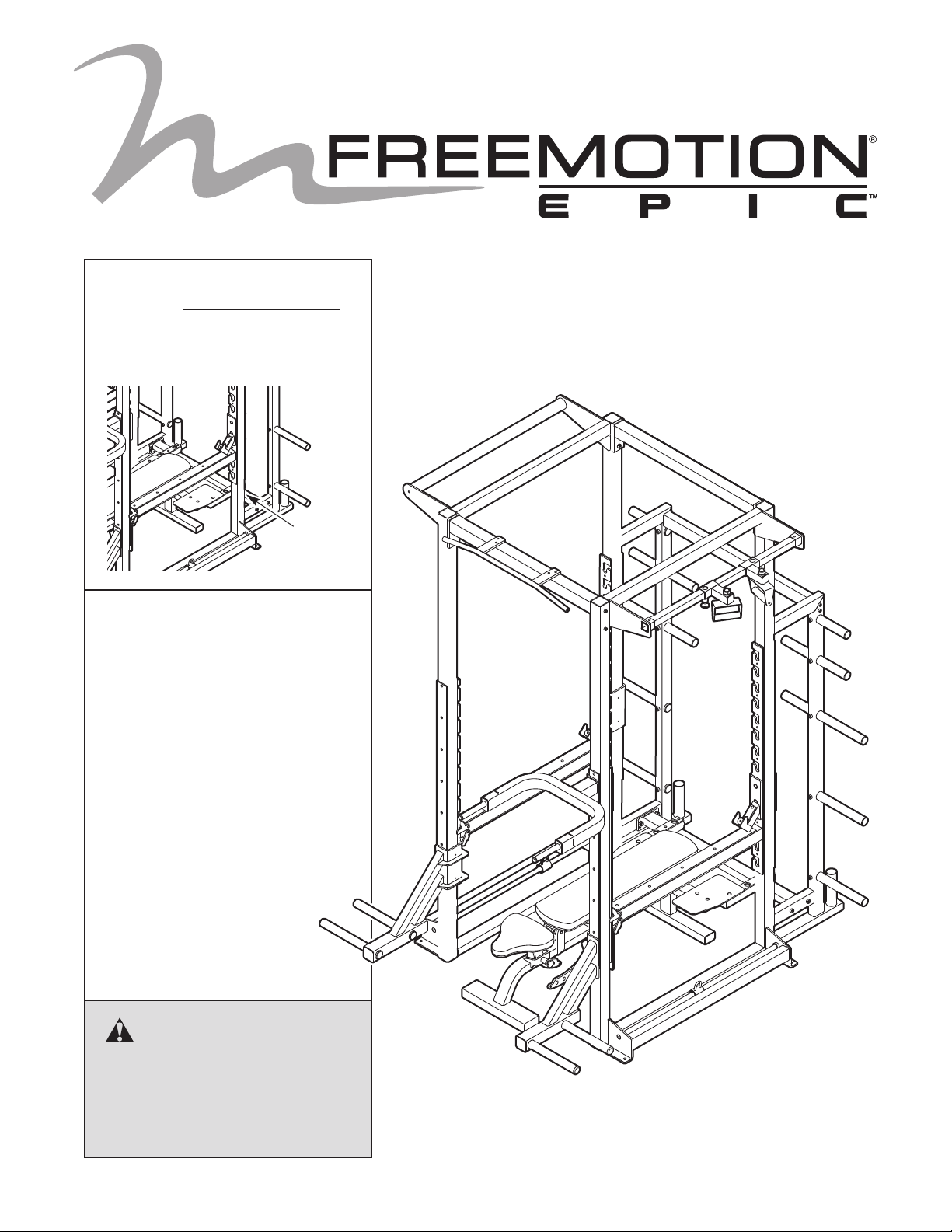
Model No. F400.0
Serial No.
Write the serial number in the
space above for reference.
Serial
Number
Decal
QUESTIONS?
If you have questions, or if parts
are damaged or missing, please
see HOW TO CONTACT
CUSTOMER CARE on the back
cover of this manual.
OWNERʼS MANUAL
CAUTION
Read all precautions and instructions in this manual before using
this equipment. Keep this manual
for future reference.
www.freemotionfitness.com
Page 2
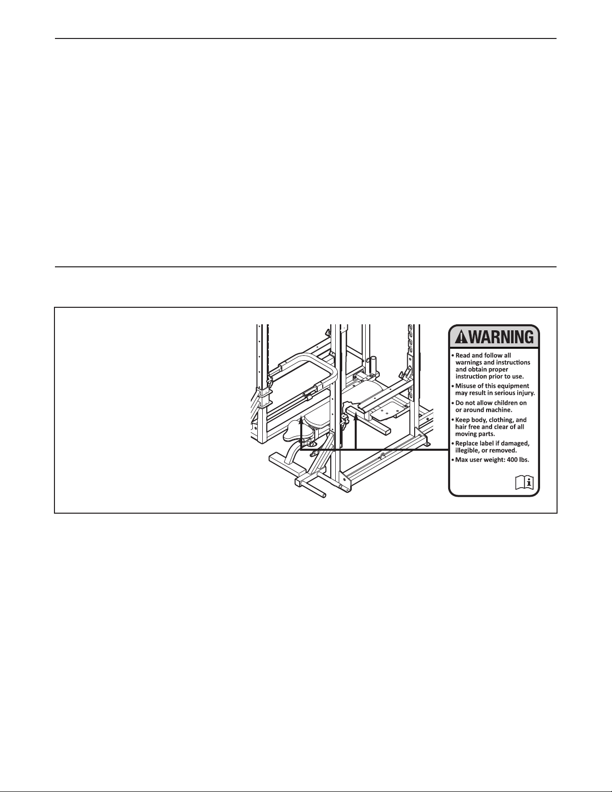
TABLE OF CONTENTS
WARNING DECAL PLACEMENT . . . . . . . . . . . . . . . . . . . . . . . . . . . . . . . . . . . . . . . . . . . . . . . . . . . . . . . . . . . . . .2
IMPORTANT PRECAUTIONS . . . . . . . . . . . . . . . . . . . . . . . . . . . . . . . . . . . . . . . . . . . . . . . . . . . . . . . . . . . . . . . .3
BEFORE YOU BEGIN . . . . . . . . . . . . . . . . . . . . . . . . . . . . . . . . . . . . . . . . . . . . . . . . . . . . . . . . . . . . . . . . . . . . . .4
PART IDENTIFICATION CHART . . . . . . . . . . . . . . . . . . . . . . . . . . . . . . . . . . . . . . . . . . . . . . . . . . . . . . . . . . . . . .5
SSEMBLY . . . . . . . . . . . . . . . . . . . . . . . . . . . . . . . . . . . . . . . . . . . . . . . . . . . . . . . . . . . . . . . . . . . . . . . . . . . . . . .6
A
ADJUSTMENT . . . . . . . . . . . . . . . . . . . . . . . . . . . . . . . . . . . . . . . . . . . . . . . . . . . . . . . . . . . . . . . . . . . . . . . . . . .11
MAINTENANCE AND TROUBLESHOOTING . . . . . . . . . . . . . . . . . . . . . . . . . . . . . . . . . . . . . . . . . . . . . . . . . . .15
PART LIST . . . . . . . . . . . . . . . . . . . . . . . . . . . . . . . . . . . . . . . . . . . . . . . . . . . . . . . . . . . . . . . . . . . . . . . . . . . . . .16
EXPLODED DRAWING . . . . . . . . . . . . . . . . . . . . . . . . . . . . . . . . . . . . . . . . . . . . . . . . . . . . . . . . . . . . . . . . . . . .17
HOW TO CONTACT CUSTOMER CARE . . . . . . . . . . . . . . . . . . . . . . . . . . . . . . . . . . . . . . . . . . . . . . .Back Cover
WARNING DECAL PLACEMENT
This drawing shows the location(s)
of the warning decal(s). If a decal
is missing or illegible, see the
back cover of this manual and
request a free replacement
decal. Apply the decal in the
location shown. Note: The
decal(s) may not be shown at
actual size.
FREEMOTION is a registered trademark of ICON IP, Inc.
2
Page 3

IMPORTANT PRECAUTIONS
WARNING: T
instructions in this manual and all warnings on your exercise rack before using your exercise rack.
FreeMotion Fitness assumes no responsibility for personal injury or property damage sustained by
or through the use of this product.
1. Before beginning any exercise program,
consult your physician. This is especially
important for persons over age 35 or persons with pre-existing health problems.
2. Use the exercise rack only as described in
this manual.
3. Use the exercise rack only on a level surface. Cover the floor beneath the exercise
rack to protect the floor.
4. It is the responsibility of the owner to ensure
that there is enough space around the exercise rack for the intended exercise. Do not
crowd the exercise rack.
5. Using the four 14 mm anchor holes to provide maximum stability, the exercise rack
must be anchored to the floor where
required or whenever possible.
6. Make sure that all parts are properly tightened before each use of the exercise rack.
7. It is the responsibility of the owner to ensure
that all users of the exercise rack are adequately informed of all precautions, have
o reduce the risk of serious injury, read all important precautions and
read and understood all warning and caution
decals, and are informed of how to use the
exercise rack properly.
8. All users of the exercise rack should be
instructed to report any injury or exercise
rack irregularity to facility staff immediately.
9. The exercise rack, bench, and stands are
designed to support a maximum user weight
of 400 lbs. (181 kg), a maximum of 495 lbs.
(225 kg) of weight, including a barbell (not
included), or a maximum total weight of 895
lbs. (406 kg), including the user weight. The
dip bar, pull-up bar, grip bar, and freestyle
bar are designed to support a maximum user
weight of 400 lbs. (181 kg).
10. Keep children under age 12 and pets away
from the exercise rack at all times.
11. Always wear athletic shoes for foot protection while using the exercise rack.
12. Over exercising may result in serious injury
or death. If you feel faint or if you experience
pain while exercising, stop immediately and
cool down.
3
Page 4
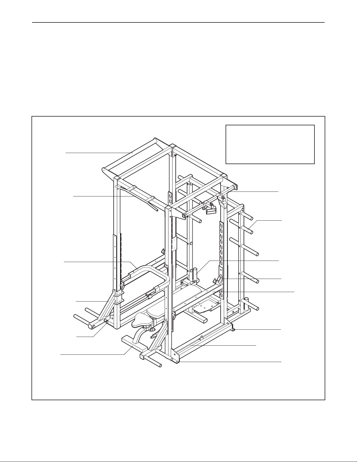
BEFORE YOU BEGIN
hank you for selecting the FREEMOTION EPIC™
T
exercise rack. The exercise rack is designed to help
you develop the major muscle groups of your body.
Whether your goal is to tone your body or build dra-
atic muscle size and strength, the exercise rack will
m
help you to achieve the specific results you want.
For your benefit, read this manual carefully before
you use the exercise rack. If you have questions
Grip Bar
Pull-up Bar
fter reading this manual, please see the back cover
a
of this manual. To help us assist you, note the product
model number and serial number before contacting
us. The model number and the location of the serial
umber decal are shown on the front cover of this
n
manual.
Before reading further, please familiarize yourself with
the parts that are labeled in the drawing below.
ASSEMBLED DIMENSIONS:
Height: 9 ft. 4 in. (284 cm)
Width: 6 ft. 2 in. (175 cm)
Depth: 8 ft. 4 in. (148 cm)
Freestyle Bar
Storage Bar
Right Side
Barbell
Dip Bar
Weight Rest
Anchor Hole
Resistance Band Rod
Bench
Note: The terms “right side” and “left side” are determined relative to a person sitting on the
seat; they do not correspond to right and left in the drawings in the manual.
Storage Post
Barbell Rest
Spotter
Left Side
Anchor Hole
Anchor Hole
4
Page 5
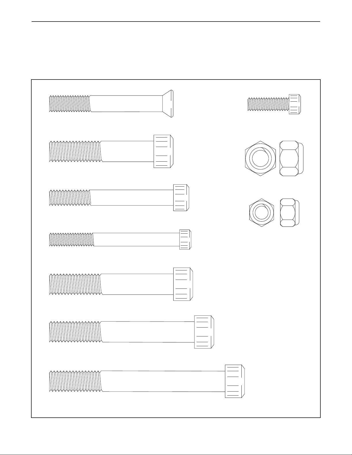
PART IDENTIFICATION CHART
1/2" x 3" Socket Bolt (70)–4
1/2" Locknut (84)–8
M8 x 25mm Socket
Screw (72)–5
M8 x 80mm Socket Screw (73)–1
3/8" x 3" Socket Screw (67)–4
1/2" x 3 1/2" Socket Screw (68)–4
1/2" x 4 1/4" Socket Bolt (69)–4
1/2" x 2 1/2" Socket Screw (66)–14
M10 Locknut
(85)–4
M10 x 70mm Flat Head Bolt (74)–4
Refer to the drawings below to identify small parts used in assembly. The number in parentheses by each drawing is the key number of the part, from the PART LIST near the end of this manual. The number following the
arentheses is the quantity needed for assembly. IMPORTANT: If you cannot find a part in the hardware kit,
p
check to see if it has been preassembled.
5
Page 6
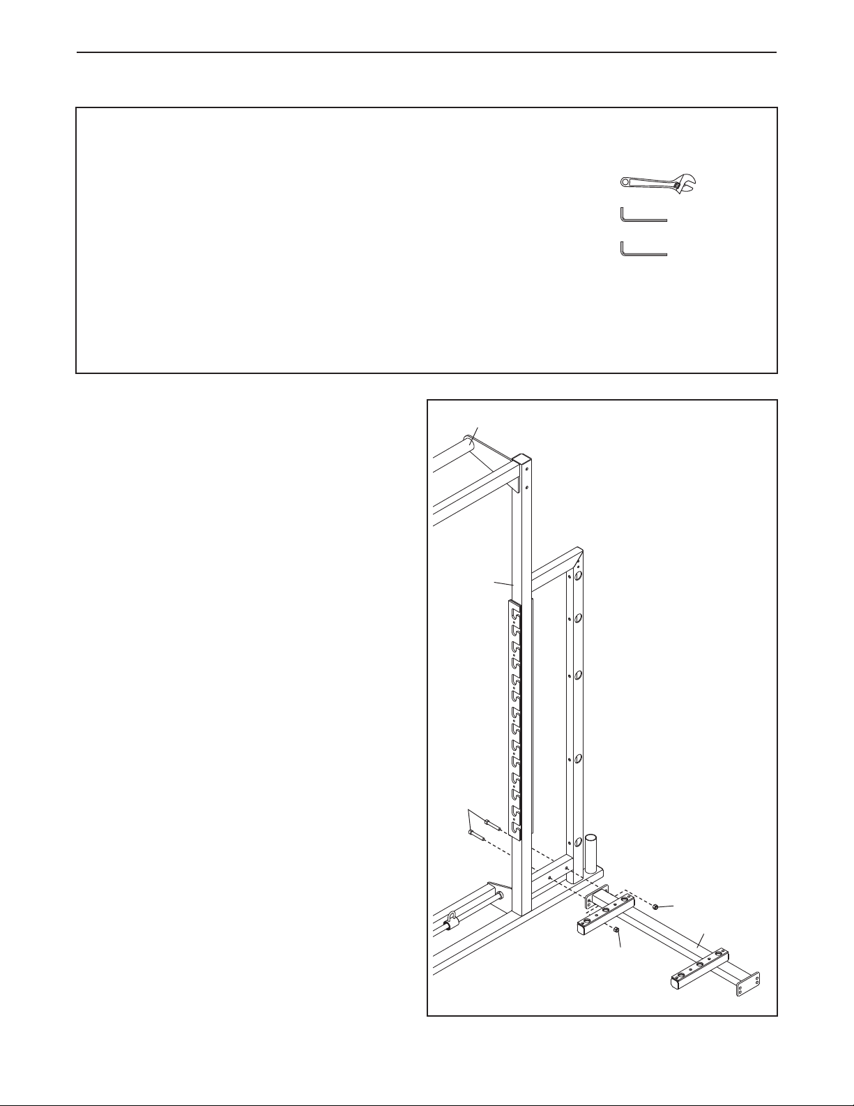
ASSEMBLY
To make assembly easier, carefully read the
following information and instructions:
Assembly requires two to four persons.
•
• Because of its weight and size, the exercise rack
should be assembled in the location where it will
be used. Make sure that there is enough clearance to walk around the exercise rack as you
assemble it.
• Place all parts in a cleared area and remove the
packing materials. Do not dispose of the packing
materials until assembly is completed.
1. Identify the Right Frame (1), which has a Grip
Bar (19) attached to the top.
Tip: See step 2. The Left Frame (2) has a
Freestyle Bar (20) attached to the top.
Orient the Right Frame (1) and the Bench
Crossbar (6) as shown. Have another person
hold the Right Frame in the position shown
until you complete this step.
• Assembly requires the following tools (not
included):
n adjustable wrench
a
a metric hex key
a standard hex key
Assembly may be more convenient if you have a
socket set, a set of open-end or closed-end
wrenches, or a set of ratchet wrenches. To avoid
damaging parts, do not use power tools.
1
19
Attach the Bench Crossbar (6) to the Right
Frame (1) with two 1/2" x 3" Socket Bolts (70)
and two 1/2" Locknuts (84).
1
70
84
6
84
6
Page 7

2. Orient the Left Frame (2) as shown.
Attach the Bench Crossbar (6) to the Left
Frame (2) with two 1/2" x 3" Socket Bolts (70)
and two 1/2" Locknuts (84). Have another per-
son hold the Left Frame in the position
shown until you complete this step.
2
20
6
84
3. Identify the Rear Crossbar (5).
Tip: See step 4. Compare the Rear Crossbar
(5) with the Center Crossbar (4) to identify
the Rear Crossbar.
Attach the Rear Crossbar (5) to the Right and
Left Frames (1, 2) with four 3/8" x 3" Socket
Screws (67).
84
2
70
3
67
1
5
2
67
7
Page 8

4. Orient the Center Crossbar (4) as shown.
Attach the Center Crossbar (4) to the Right and
Left Frames (1, 2) with two 1/2" x 3 1/2" Socket
Screws (68), two 1/2" x 4 1/4" Socket Bolts
(69), and two 1/2" Locknuts (84).
4
68
9
6
84
1
4
5. Orient the Front Crossbar (3) as shown.
Attach the Front Crossbar (3) to the Right and
Left Frames (1, 2) with two 1/2" x 3 1/2" Socket
Screws (68), two 1/2" x 4 1/4" Socket Bolts
(69), and two 1/2" Locknuts (84).
84
5
68
2
68
69
69
84
3
1
84
2
68
69
8
Page 9

6. Identify the Short Dual Weight Bars (38), the
ong Dual Weight Bars (39), the Short Weight
L
Bars (40), the Medium Weight Bars (41), and
the Long Weight Bars (not shown).
Tip: See the drawing in assembly step 7 to
identify the Long Weight Bars (42).
Attach a Short Weight Bar (40) to the Left
Frame (2) in the location shown with a 1/2" x 2
1/2" Socket Screw (66).
6
40
38
40
Attach the other Short Weight Bar (40), the
Short Dual Weight Bars (38), the Long Dual
Weight Bars (39), and the Medium Weight
Bars (41) in the same way.
WARNING: Each Short Dual
Weight Bar (38) can hold up to 200 lbs.
(91 kg). Each Long Dual Weight Bar (39)
can hold up to 350 lbs. (159 kg). Each
Short Weight Bar (40) can hold up to 80
lbs. (36 kg). Each Medium Weight Bar
(41) can hold up to 270 lbs. (122 kg). Do
not place a total of more than 495 lbs.
(225 kg), including a barbell (not
included), on the barbell rests, the
weight rests, and the Weight Bars.
7. Attach two Long Weight Bars (42) to the Right
Weight Rest (23) with two 1/2" x 2 1/2" Socket
Screws (66).
Repeat this step for the Left Weight Rest
(not shown).
39
41
41
7
42
23
66
2
38
39
41
41
66
9
Page 10

8. Identify the Right and Left Spotter Steps (17,
18) and orient them as shown.
ttach the Left Spotter Step (18) to the Bench
A
Frame (7) with two M10 x 70mm Flat Head
olts (74) and two M10 Locknuts (85).
B
8
17
74
18
Attach the Right Spotter Step (17) in the
same way.
9. Attach the Backrest (11) to the Backrest Frame
(9) with an M8 x 25mm Socket Screw (72) and
an M8 x 80mm Socket Screw (73).
To adjust the angle of the Backrest (11), hold
the Backrest with one hand and pull the indicated Adjustment Knob (97) with your other
hand. Pivot the Backrest to the desired angle,
and reengage the Adjustment Knob into the
Backrest Adjustment Bracket (15).
WARNING: Always hold the
Backrest (11) before pulling the
Adjustment Knob (97); the Backrest can
fall with great force.
7
85
9
11
72
9
97
15
73
10. Attach the Seat (10) to the Seat Frame (8) with
four M8 x 25mm Socket Screws (72).
To adjust the angle of the Seat (10), hold the
Seat with one hand and pull the indicated
Adjustment Knob (97) with your other hand.
Pivot the Seat to the desired angle, and reengage the Adjustment Knob into the Seat
Adjustment Bracket (16).
11. Make sure that all parts of the exercise rack are properly tightened. The use of all remaining parts will
be explained in ADJUSTMENT, beginning on page 11.
10
10
8
16
97
72
10
Page 11

ADJUSTMENT
his section explains how to adjust the exercise rack. Make sure that all parts are properly tightened each time
T
the exercise rack is used. Replace any worn parts immediately.
HOW TO ATTACH THE BENCH
See the upper drawing. To use the bench with the
exercise rack, set the Right and Left Spotter Steps
(17, 18) on the Bench Crossbar (6). Make sure
that the pins on the underside of the Spotter
Steps are inserted securely into the indicated
holes in the Bench Crossbar.
HOW TO ADJUST THE BACKREST
See the upper drawing. To adjust the angle of the
Backrest (11), hold the Backrest with one hand and
pull the indicated Adjustment Knob (97) with your
other hand. Pivot the Backrest to the desired angle,
and reengage the Adjustment Knob into the
Backrest Adjustment Bracket (15).
HOW TO ADJUST THE SEAT
See the lower drawing. To adjust the angle of the
Seat (10), hold the Seat with one hand and pull the
indicated Adjustment Knob (97) with your other
hand. Pivot the Seat to the desired angle, and reengage the Adjustment Knob into the Seat Adjustment
Bracket (16).
6
17
18
11
97
15
10
16
97
HOW TO ATTACH THE SPOTTERS
Orient a Spotter (26) as shown.
At the desired height, insert the Spotter (26) into
the slots in the Short and Long Adjustment Brackets
(27, 86) on the Left Frame (2).
Press the Spotter Lock (29) on the upper side of
the Spotter (26) downward against the Short
Adjustment Bracket (27).
Attach the other Spotter (26) to the other side of
the exercise rack in the same way.
WARNING: Always set both
Spotters (26) at the same height.
26
86
26
29
27
2
11
Page 12

HOW TO ATTACH THE RESTS AND THE
DIP BAR
ee the upper drawing. Orient the Left Barbell
S
Rest (22) as shown.
At the desired height, insert the Left Barbell Rest
(22) into the slots in the Long Adjustment Bracket
(86) on the Left Frame (2).
Attach the Right Barbell Rest (21) to the Right
Frame (1) in the same way.
See the lower drawing. Attach the Right and Left
Weight Rests (23, 24) and the Dip Bar (28) to the
Right and Left Frames (1, 2) in the same way.
WARNING: Always set both
Barbell Rests (21, 22) and both Weight
Rests (23, 24) at the same height.
The Barbell Rests (21, 22), the Weight Rests
(23, 24), and the weight bars are designed to
support a maximum weight of 495 lbs. (225
kg), including a barbell (not included).
Always place the same amount of weight on
both sides of your barbell.
The Dip Bar (28) is designed to support a
maximum user weight of 400 lbs. (181 kg).
23
21
1
86
22
2
1
28
2
24
12
Page 13

HOW TO ATTACH THE STANDS
To use the Short Stand (13) or the Tall Stand (not
shown) with the exercise rack, set the Stand on the
Bench Crossbar (6). Make sure that the pins on
the underside of the Stand are inserted securely
into the holes in the Bench Crossbar.
13
6
HOW TO ATTACH RESISTANCE BANDS
To use resistance bands (not included) with a barbell (not included), attach the resistance bands to
the Loop Brackets (45) on the Rods (43).
45
43
13
Page 14

HOW TO ADJUST THE FREESTYLE FRAMES
To adjust the Left Freestyle Frame (30), pull the left
reestyle Knob (37), slide the Left Freestyle Frame
F
to the desired position, and then release the
reestyle Knob.
F
Adjust the Right Freestyle Frame (87) in the
same way.
WARNING: The pull-up bar, the
grip bar, and the freestyle bar are designed
to support a maximum user weight of
400 lbs. (181 kg).
30
37
87
37
14
Page 15

MAINTENANCE AND TROUBLESHOOTING
or optimal performance of the exercise rack and to reduce the chances of injury to users, you must perform
F
preventive maintenance on a regular basis. Instruct all personnel to perform the procedures described in this
section. Personnel must also record and report any accident. To maintain the exercise rackʼs warranty, use only
FREEMOTION parts for repair or replacement. If there are any questions or concerns, see HOW TO CONTACT
USTOMER CARE on the back cover of this manual.
C
DAILY MAINTENANCE
Upholstery and Frame—General Cleaning
1. Clean the exercise rack using a soft cloth damp-
ened with a light solution of mild soap and warm
water. If necessary, use a soft bristle brush with
the cleaning solution.
2. Rinse the area thoroughly using a soft cloth damp-
ened with clean water. Dry thoroughly.
Upholstery—Difficult Stains
1. Spray the stain with a non-abrasive household
cleaner such as FORMULA 409
GREEN®, or a similar product. Rub the stained
area gently and let the cleaning solution sit for a
few minutes.
2. Rinse the area thoroughly using a soft cloth damp-
ened with clean water. Dry thoroughly.
3. Repeat these steps, if necessary, using a soft-bris-
tle brush.
Optional Method for Difficult Stains
1. Rub the stained area gently using a soft cloth
dampened with rubbing alcohol.
2. Rinse the area thoroughly using a soft cloth damp-
ened with clean water. Dry thoroughly.
CAUTION: When using any cleaning product, try it
first in an unnoticeable place to ensure that there is no
damage to the material. Follow the directions and the
safety precautions of the manufacturer of each cleaning product used. FreeMotion Fitness and its vendors
cannot be held liable for damage or injuries resulting
from the use or misuse of cleaning products. IMPOR-
TANT: Do not use abrasive cleaners, which may
scratch the exercise rack. Strong cleaners and
abrasives will damage decals; use caution around
decals. Do not use solvents such as lacquer thinner, kerosene, gasoline, or similar liquids.
®
cleaner, SIMPLE
WEEKLY MAINTENANCE
Hardware
Check all nuts and bolts, and tighten them if necessary.
IMPORTANT: All FREEMOTION cushions have
dense plywood supports with tee-nuts that are
used to bolt the cushions to the exercise rack.
Because the tee-nuts are held by the plywood,
they will not withstand the torque that standard
nuts and bolts will. When tightening the bolts
securing a cushion, turn them only until they are
snug and the cushion does not move or feel loose.
Overtightening may strip the tee-nuts from the plywood and make it impossible to remove the
cushion in the future.
Wheels
The wheels should roll easily. Tighten or replace the
wheels if necessary.
Adjustment Knob
If an adjustment knob sticks, it will need to be relubricated. Unscrew the knob and apply a light coating of
lithium grease. Reassemble the knob as shown in the
drawing below. If the adjustment knob still does not
function properly, the spring may need to be replaced.
To order a new spring, see HOW TO CONTACT CUSTOMER CARE on the back cover of this manual.
Adjustment Knob
Pin
Spring
Frame
Knob
15
Page 16

PART LIST—Model No. F400.0 R0210A
Key No. Qty. Description Key No. Qty. Description
11Right Frame
21Left Frame
31Front Crossbar
4
51Rear Crossbar
61Bench Crossbar
71Bench Frame
81Seat Frame
91Backrest Frame
10 1 Seat
11 1 Backrest
12 1 Tall Stand
13 1 Short Stand
14 1 Pull-up Bar
15 1 Backrest Adjustment Bracket
16 1 Seat Adjustment Bracket
17 1 Right Spotter Step
18 1 Left Spotter Step
19 1 Grip Bar
20 1 Freestyle Bar
21 1 Right Barbell Rest
22 1 Left Barbell Rest
23 1 Right Weight Rest
24 1 Left Weight Rest
25 1 Bumper Pad
26 2 Spotter
27 2 Short Adjustment Bracket
28 1 Dip Bar
29 4 Spotter Lock
30 1 Left Freestyle Frame
31 2 Freestyle Bracket
32 2 Freestyle Handle
33 4 Freestyle Bushing
34 2 Lock Ring
35 2 Upper Lock Pin
36 2 Freestyle Spring
37 2 Freestyle Knob
38 2 Short Dual Weight Bar
39 2 Long Dual Weight Bar
40 2 Short Weight Bar
41 4 Medium Weight Bar
42 4 Long Weight Bar
43 2 Rod
44 4 Inner Snap Ring
45 2 Loop Bracket
46 2 Loop Bushing
47 2 Front Strike Plate
48 2 Rear Strike Plate
49 2 Front Wear Pad
50 2 Rear Wear Pad
1 Center Crossbar
51 5 Small Wear Pad
52 4 Spotter Strike Plate
53 2 Bench Wear Pad
4 1 Bumper
5
55 2 Bearing
56 1 Axle
57 2 Snap Ring
58 2 Small Strike Plate
59 2 Roller
60 2 Retention Collar
61 2 Handgrip
62 62 1/4" x 3/4" Flat Head Socket Screw
63 26 3/8" x 3 1/2" Flat Head Screw
64 10 1/4" x 1/2" Flat Head Socket Screw
65 2 M6 x 15mm Screw
66 14 1/2" x 2 1/2" Socket Screw
67 4 3/8" x 3" Socket Screw
68 4 1/2" x 3 1/2" Socket Screw
69 4 1/2" x 4 1/4" Socket Bolt
70 4 1/2" x 3" Socket Bolt
71 6 3/8" x 3/4" Socket Screw
72 5 M8 x 25mm Socket Screw
73 1 M8 x 80mm Socket Screw
74 4 M10 x 70mm Flat Head Bolt
75 8 3/8" x 4" Socket Bolt
76 2 M10 x 110mm Bolt
77 2 M10 x 80mm Bolt
78 1 M6 x 25mm Screw
79 2 Washer
80 2 M10 x 16mm Screw
81 2 3/8" x 2 1/2" Socket Bolt
82 4 Nylon Washer
83 6 3/8" Locknut
84 8 1/2" Locknut
85 10 M10 Locknut
86 2 Long Adjustment Bracket
87 1 Right Freestyle Frame
88 2 Lower Lock Pin
89 4 3/8" Jam Nut
90 4 #10 x 1/8" Set Screw
91 4 5/16" x 1/4" Set Screw
92 2 1/4" x 1 3/4" Hex Bolt
93 2 1/4" Nut
94 2 Wheel
95 2 M10 x 65mm Bolt
96 1 Bracket Plate
97 2 Adjustment Knob
98 2 Bench Spring
*–Userʼs Manual
Note: Specifications are subject to change without notice. For information about ordering replacement parts, see
the back cover of this manual. *These parts are not illustrated.
16
Page 17

1
19
26
86
27
29
89
38
40
43
44
45
46
44
47
48
50
49
52
52
21
51
58
59
63
62
63
62
63
62
63
62
63
63
63
63
63
63
62
62
62
62
62
62
62
62
62
6
4
62
66
66
67
68
6
9
68
69
70
71
71
75
29
91
91
66
66
66
41
41
39
EXPLODED DRAWING A—Model No. F400.0 R0210A
17
Page 18

3
5
4
7
8
9
1
1
12
15
16
17
23
25
18
6
88
98
97
42
51
53
53
54
55
55
56
57
57
62
62
62
62
64
65
72
72
73
74
74
66
14
75
75
10
76
76
77
78
82
82
83
83
84
84
85
85
84
84
84
84
84
84
79
80
79
85
85
95
94
85
94
95
13
96
88
98
97
EXPLODED DRAWING B—Model No. F400.0 R0210A
18
Page 19

2
20
22
24
2
6
27
28
29
30
87
31
31
32
32
33
33
33
33
34
35
36
37
35
36
37
41
42
42
43
44
45
46
44
47
48
49
50
5
1
51
52
52
58
59
51
60
60
61
61
62
62
62
62
62
62
62
62
63
63
63
63
63
63
63
63
63
63
62
62
62
62
64
64
64
62
66
66
66
67
68
68
69
69
70
66
66
64
64
75
75
71
71
71
81
81
29
89
89
83
83
86
91
91
90
90
92
93
34
92
93
62
41
39
38
40
EXPLODED DRAWING C—Model No. F400.0 R0210A
19
Page 20

HOW TO CONTACT CUSTOMER CARE
If you have questions after reading this manual, or if parts are damaged or missing, please contact Customer
Care at the phone numbers or addresses listed below. Please note the model number, serial number, and
ame of the product (see the front cover of this manual) before contacting Customer Care. If you are
n
ordering replacement parts, please also note the key number and description of each part (see the PART
LIST and the EXPLODED DRAWING near the end of this manual).
In the United States and Canada
Call: 1-800-201-2109, Mon.–Fri. 8 a.m.–5 p.m. MT
Write:
FreeMotion Fitness
1500 South 1000 West
Logan, UT 84321-9813
United States
Outside the United States and Canada
Call: 001-435-786-3521
Email: intlcustomercare@freemotionfitness.com
Part No. 292331 R0210A Printed in USA © 2010 ICON IP, Inc.
 Loading...