

Freeman FRM-S810 Service Manual
■SI*.
^r'-:
''Vj
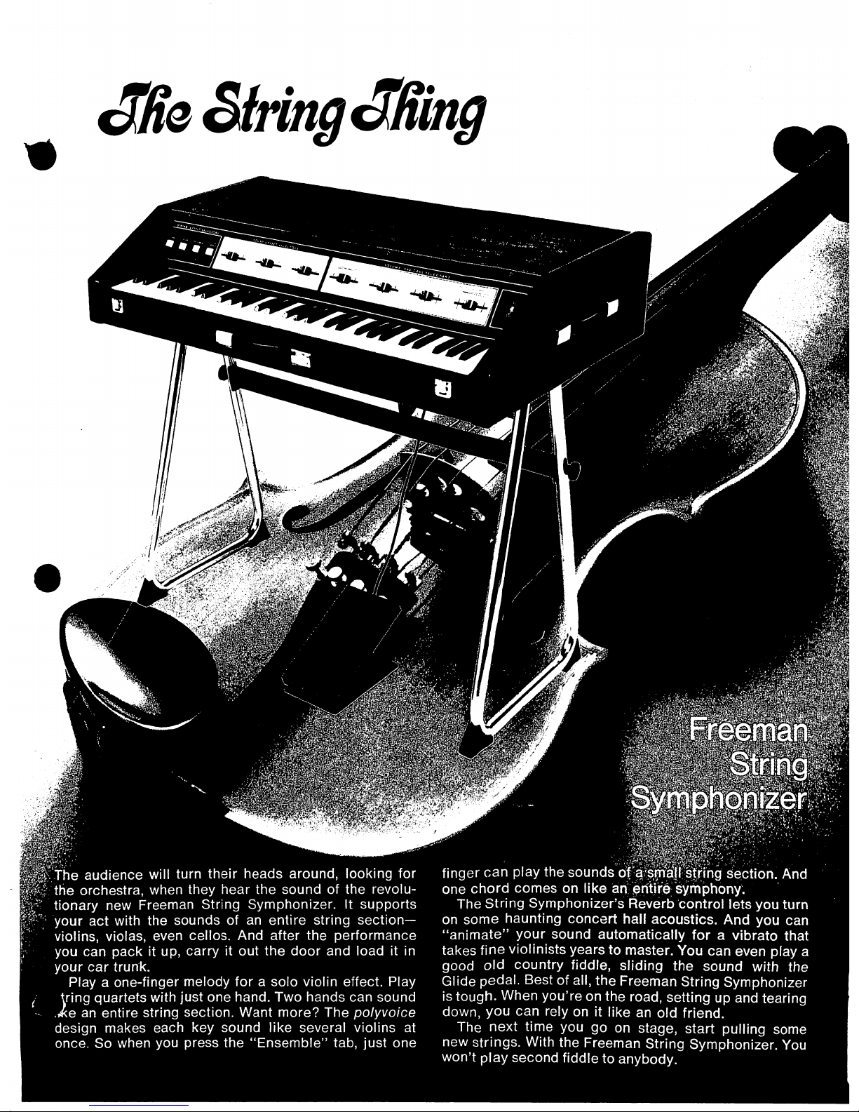
.The
audience
will
turn
their
heads
around,
looking
for
the
orchestra,
when
they
hear
the
sound
of
the
revolu
tionary
new
Freeman
String
Symphonizer.
It
supports
your
act
with
the
sounds
of
an
entire
string
section-
violins,
violas,
even
cellos.
And
after
the
performance
you
can
pack
it
up,
carry
it
out
the
door
and
load
it
in
your
car
trunk.
Play a one-finger
melody
for a solo
violin
effect.
Play
tring
quartets
with
just
one
hand.
Two
hands
can
sound
Ae
an
entire
string
section.
Want
more?
The
polyvoice
design
makes
each
key
sound
like
several
violins
at
once.
So
when
you
press
the
"Ensemble"
tab,
just
one
finger
can
play the
sounds
c$^;^
And
one
chord
comes
on
like
ari^rftire^yrhJDhony;
The
String
Symphonizer's
Reverb
control
lets
you
turn
on
some
haunting
concert
hall
acoustics.
And
you
can
"animate"
your
sound
automatically
for a vibrato
that
takes
fine
violinists
years
to
master.
You
can
even
play
a
good
old
country
fiddle,
sliding
the
sound
with the
Glide
pedal.
Best
of
all,
the
Freeman
String
Symphonizer
is
tough.
When
you're
on
the
road,
setting
up
and
tearing
down,
you
can
rely
on
it
like
an
old
friend.
The
next
time
you
go
on
stage,
start
pulling
some
new
strings.
With
the
Freeman
String
Symphonizer.
You
won't
play
second
fiddle
to
anybody.
izor
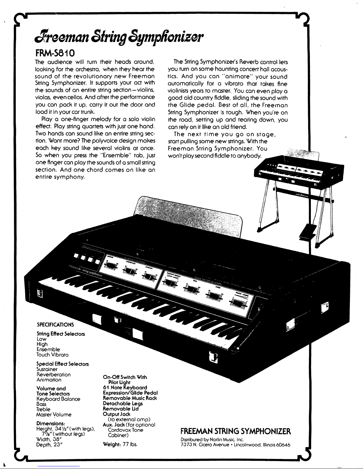
FRM-S810
The
oudience
will
turn
their
heads
around,
looking
for
the
orchestra,
when
they
hear
the
sound
of
the
revolutionary
new
Freeman
String
Symphonizer.
It
supports
your
act
with
the
sounds
of
an
entire
string
section—violins,
violas,
even
cellos.
And
after
the
performance
you
can
pack
it
up,
carry
it
out
the
door
and
load
it
in
your
car
trunk.
Play a one-finger
melody
for a solo
violin
effect.
Play
string
quartets
with
just
one
hand.
Two
hands
can
sound
like
an
entire
string
sec
tion.
Want
more?
The
polyvoice
design
makes
each
key
sound
like
several
violins
at
once.
So
when
you
press
the
"Ensemble"
tab,
just
one
finger
can
play
the
sounds
of a small
string
section.
And
one
chord
comes
on
like
an
entire
symphony.
The
String
Symphonizer's
Reverb
control
lets
you
turn
on
some
haunting
concert
hall
acous
tics.
And
you
can
"animate"
your
sound
automatically
for a vibrato
that
takes
fine
violinists
years
to
master.
You
can
even
play
a
good
old
country
fiddle, sliding
the
sound
with
the
Glide
pedal.
Best
of
all,
the
Freeman
String
Symphonizer
is
tough.
When
you're
on
the
road,
setting
up
and
tearing
down,
you
can
rely
on
it
like
an
old
friend.
The
next
time
you
go
on
stage,
start
pulling
some
new
strings.
With
the
Freeman
String
Symphonizer.
You
won't
play
second
fiddle
to
anybody.
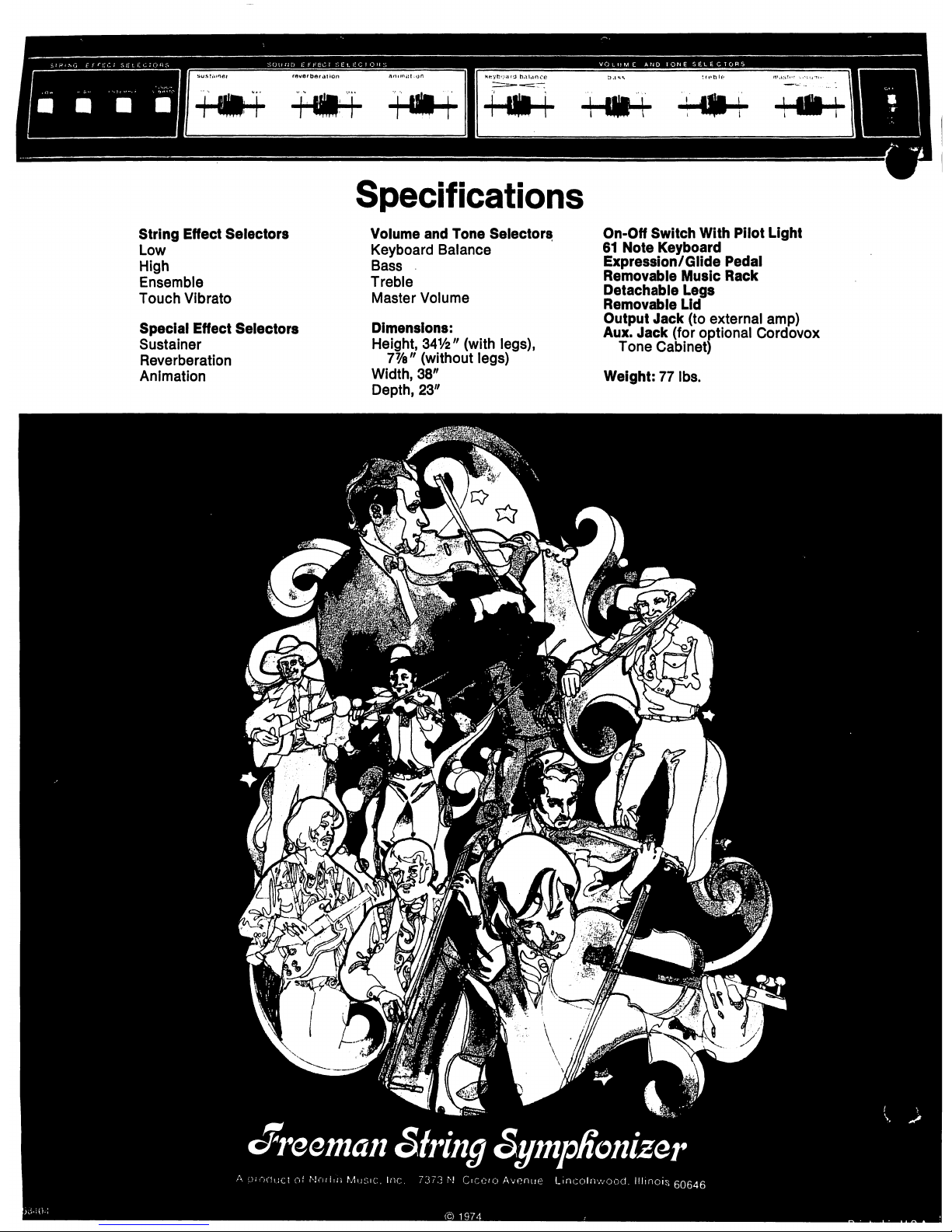
SPECIFICATIONS
String
Effect
Selectors
Low
High
Ensemble
Touch
Vibrato
Special
Effect
Selectors
Sustainer
Reverberation
Animation
Volume
and
Tone
Selectors
Keyboard
Balance
Boss
Treble
Master
Volume
Dimensions:
Height,
34W
(with
legs),
Tk"
(without
legs)
Width,
38"
Depth,
23"
On-Off
Switch
With
Riot
Light
61
Note
Keyboard
Expression/Glide
Pedal
Removable
Music
Rack
Detachable
Legs
Removable
Lid
Output
Jack
(ro
external
amp)
Aux.
Jack
(for
optional
Cordovox
Tone
Cabinet)
Weight:
77
lbs.
FREEMAN
STRING
SYMPHONIZER
Distributed
by
Norlin
Music
Inc.
7373
N.
Cicero
Avenue • Lincolnwood,
Illinois
60646
String
Effect
Selectors
Low
High
Ensemble
Touch
Vibrato
Special
Effect
Selectors
Sustainer
Reverberation
Animation
Specifications
Volume
and
Tone
Selectors
Keyboard
Balance
Bass
Treble
Master
Volume
Dimensions:
Height,
34V2"
(with
legs),
77/e/;
(without
legs)
Width,
38"
Depth,
23"
On-Off
Switch
With
Pilot
Light
61
Note
Keyboard
Expression/Glide
Pedal
Removable
Music
Rack
Detachable
Legs
Removable
Lid
Output
Jack
(to
external
amp)
Aux.
Jack
(for
optional
Cordovox
Tone
Cabinet)
Weight:
77
lbs.
c/reeman
String
SympRoniz&r
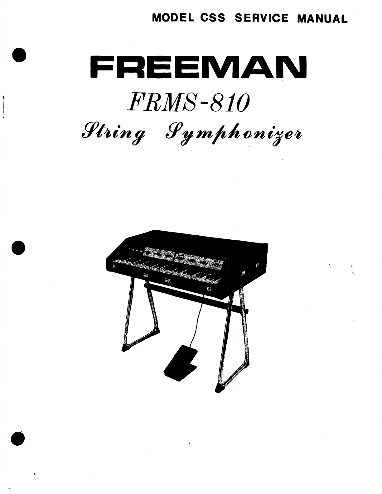
MODEL
CSS
SERVICE
MANUAL
FREEMAN
FRMS-810
TABLE
OF
CONTENTS
SERVICE
INFORMATION
Specifications
1
Circuit
Description
*
2
Adjustments
3
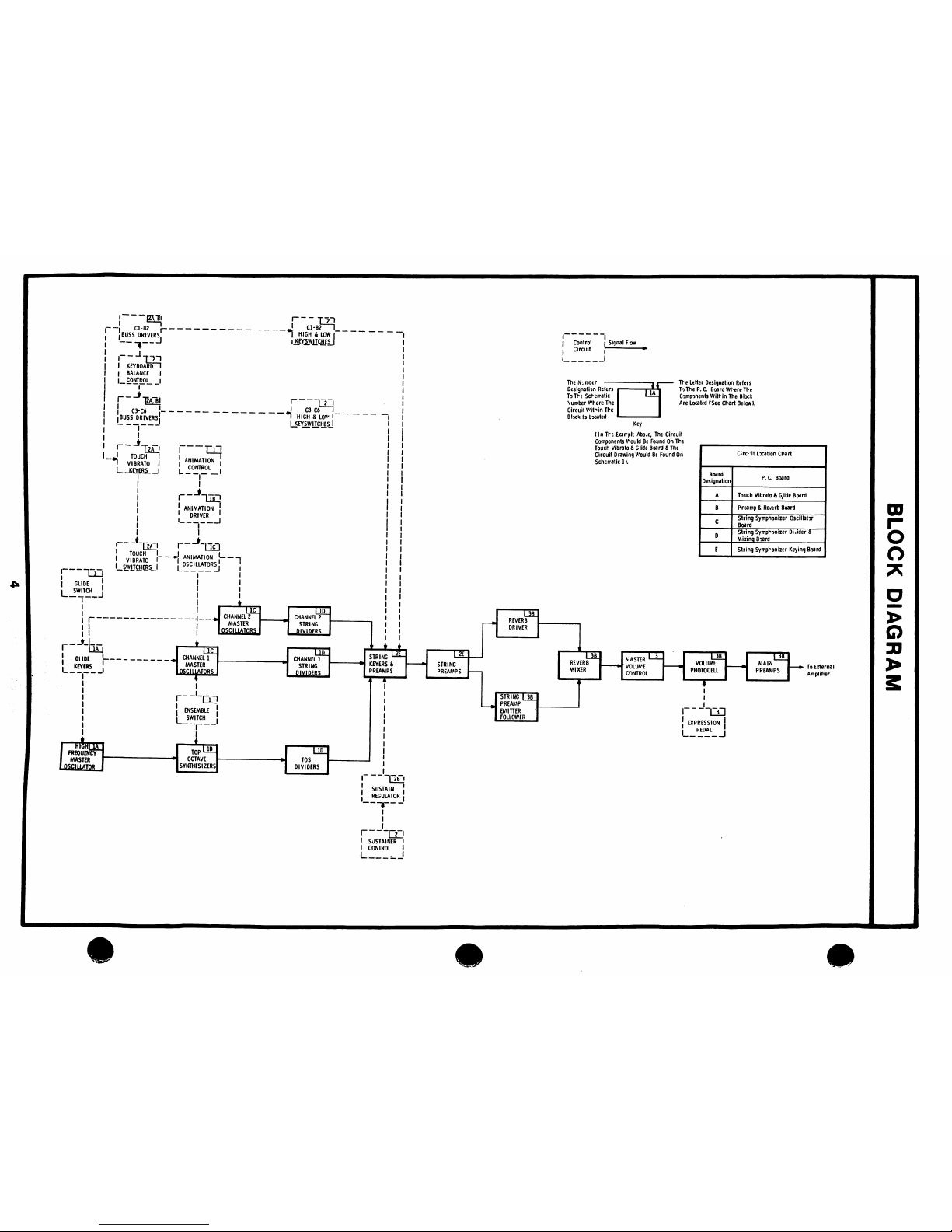
Block
Diagram
4
SCHEMATICS
Drawing
No.1
Glide,
Tone
Generators,
Animation
&
Dividers
5
Drawing
No.2
String
&
Touch
Vibrato
Keying
6
Drawing
No.3
Reverb,
Preamps & Expression
Pedal
8
Drawing
No.4
Power
Supply
,
9
CHARTS & DIAGRAMS
String
Symphonizer
Keying
Board
10
Diode
Keying
Chart
12
Transistor
Basing
Diagram
14
Transistor
Location
Chart
15
PHOTOGRAPHS
String
Symphonizer
Oscillator
Board
16
String
Symphonizer
Divider
&
Mixing
Board
17
Touch
Vibrato & Glide
Board
18
String
Symphonizer
Keying
Board
19
Preamp & Reverb
Board
20
Power
Supply
Board
21
Power
Supply
Chassis
22
PARTS
Parts
Information
23
Parts
List
24
993-024277
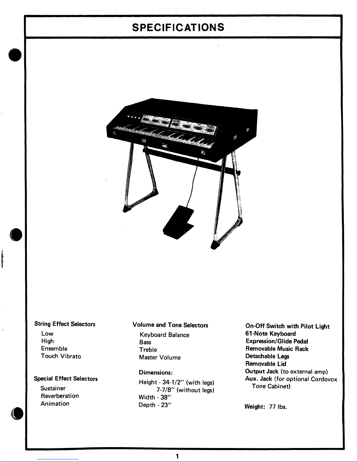
SPECIFICATIONS
String
Effect
Selectors
Low
High
Ensemble
Touch
Vibrato
Special
Effect
Selectors
Sustainer
Reverberation
Animation
Volume
and
Tone
Selectors
Keyboard
Balance
Bass
Treble
Master
Volume
Dimensions:
Height
-34-1/2"
(with
legs)
7-7/8"
(without
legs)
Width -38"
Depth -23"
On-Off
Switch
with
Pilot
Light
61-Note
Keyboard
Expression/Glide
Pedal
Removable
Music
Rack
Detachable
Legs
Removable
Lid
Output
Jack
(to
external
amp)
Aux.
Jack
(for
optional
Cordovox
Tone
Cabinet)
Weight:
77
lbs.
CIRCUIT
DESCRIPTION
SCHEMATIC
1
GLIDE,
TONE
GENERATORS,
ANIMATION & DIVIDERS
There
are
three
generator
systems
used — Channel
1,
Channel
2
and
the
Top
Octave
Synthesizers.
Channel 2 always
has an
output
as
long
as
the
high
or
low
pushbuttons
are
on
while
the
TOS
and
Channel 1 generators
have
an
output
only
when
the
ensemble
pushbutton
is
pressed.
Pressing
the
Glide
Switch
on
the
Expression
Pedal
acti
vates
the
Glide
circuitry
which
de-tunes
the
three
generator
systems
by a half
step.
Q1
GLIDE
SWITCHER
When
the
Glide
Switch
is
pressed,
a
ground
is
applied
to the
Glide
Switcher
causing
it
to
conduct,
applying
negative
volt
age
to
the
bases
of
the
TOS
Glide
Keyer
Q2
and
the
Channel
1 & 2
Glide
Keyer
Q3.
Q2,
Q3
TOS
GLIDE
KEYER,
CHANNEL 1 & 2 GLIDE
KEYER
With
the
Glide
Switch
on,
negative
voltage
is
applied
to
the
bases
of
Q2 & Q3
from
the
Glide
Switcher
Q1,
causing
them
to
conduct.
When
Q2 & Q3
conduct,
negative
voltage
is
applied
to
their
respective
oscillators
shifting
the
frequency
and
creating
the
Glide
effect.
The
TOS
Glide
Adjustment
VR1
adjusts
the
amount
of
TOS
frequency
shift.
Q4-Q6,
ICMC3
HIGH
FREQUENCY
MASTER
OSCIL
LATOR,
BUFFER,
WAVE
SHAPER,
TOP
OCTAVE
SYNTHESIZERS
AND
DIVIDERS
With
the
ensemble
pushbutton
on,
the
High
Frequency
Mas
ter
Oscillator
Q4,
creates a high
frequency
signal
which
is
applied
to
the
Top
Octave
Synthesizers
IC1 & IC2
via
the
Buffer
Q5
and
Wave
Shaper
Q6.
Here
the
signal
is
divided
to
create
twelve
specific
octave
frequencies
which
are
applied
to
the
IC
Dividers
IC3.These
frequencies
are
then
divided
in
half
several
times,
creating
lower
octave
frequencies.
The
outputs
are
then
applied
to
the
String
Keyers.
The
Buffer
Q5
acts
as
an
isolation
stage
between
the
Master
Oscillator
Q4
and
the
TOS
IC1 & IC2,
preventing
any
change
in
Master
Oscillator
frequency
due
to
change
in
circuit
load.
The
Wave
Shaper
Q6
converts
signal
from
the
High
Fre
quency
Master
Oscillator
Q4
into
the
proper
drive
signal
for
the
TOS.
Q7
ANIMATION
DRIVER
The
Animation
Driver
supplies
the
operating
voltage
for
the
Animation
Oscillators.
How
hard
the
Driver
turns
on,
or
how
much
voltage
is
supplied
to
the
Animation
Oscillators
is
determined
by
the
Animation
Control
VR2.
Q8-Q19
ANIMATION
OSCILLATORS
Voltage
from
Animation
Driver
Q7
is
applied
to
these
oscil
lators.
This
causes
the
Animation
Oscillators
to
produce
low
frequency
signals
which
are
applied
to
the
Channel 1 &
Chan
nel 2 Master
Oscillator
circuits
shifting
the
frequency
of
the
Master
Oscillators
high
and
low
creating
an
animation
or
vibrato
effect.
Q20-Q23,
IC4 & IC5
CHANNEL 1 & 2 MASTER
OSCILLATORS
8c
DIVIDERS
The
Channel 1 & 2 Master
Oscillators
run
continuously,
producing
high
frequency
audio
signals.
These
signals
are
then
applied
to
their
associated
IC
Divider
where
the
fre
quencies
are
divided
in
half
several
times.
The
outputs
of
Channel 1 &
Channel 2 Dividers
are
then
applied
to
the
String
Keyers.
NOTE:
The
Channel 1 Master
Oscillators,
although
they
run
continuously,
only
have
an
output
to the
Dividers
when
the
ensemble
pushbutton
is
on.
SCHEMATIC
2
STRING
KEYING & VIBRATO
With
the
High
and/or
Low
pushbutton
on,
positive
voltage
is
applied
through
the
emitter
base
junction
of
the
C3-C6
and
C1-B2
Buss
Drivers
Q26 & Q28
to
the
High
and
Low
key-
switch buss
bars.
Pressing a keyswitch
lowers
the
voltage
on
the
base
of
Q26
and
Q28,
turning
it
on
and
applying
positive
voltage
to
the
touch
vibrato
keying
circuit.
Also,
positive
voltage
from
the
keyswitch
buss
bar
is
applied
to
the
String
Keyer
circuit,
where
audio
signal
from
the
TOS
Generator
and
Channel 1 & 2 Generators
is
combined
and
passed
through
the
String
Keyer.
This
combined
signal
is
then
applied
to
a
Collector
Octave
Preamp
and
then
the
String
Preamps
Q48
&
Q49
before
being
sent
to
the
Reverb
Driver
Q51
and
the
String
Emitter
Follower
Q52.
Q25-Q28,
C3-C6 & C1-B2
BUSS
DRIVERS
Positive
voltage
from
the
Keyboard
Balance
Control
VR4
is
applied
to the
bases
of
Q25 & Q27,
causing
them
to
conduct
which
applies
voltage
through
the
emitter
base
junction
of
Q26 & Q28
to
the
High & Low
Keyswitch
Buss
Bars.
Q29-Q36
TOUCH
VIBRATO
KEYERS & SWITCHERS
Pressing
a
keyswitch
lowers
the
voltage
on
the
base
of
its
associated
Buss
Driver
Q26
or
Q28
causing
it
to
conduct
which
applies
a
positive
voltage
to
the
base
of
Touch
Vibrato
Keyer
Q29.
This
causes
Q29
to
conduct
which
creates
a
pulse
across
the 3 UF
capacitor,
lowering
the
voltage
on
the
base
of
Touch
Vibrato
Keyer
Q30
and
momentarily
turning
it
off.
With
the
touch
vibrato
pushbutton
on,
voltage
from
the
collector
of
Q30
is
applied
to*
the
bases
of
the
Touch
Vibrato
Switchers
Q31-Q36,
causing
them
to
conduct
momentarily
turning
off
the
Animation
Oscillators.
As
the 3 UF
capacitor
charges,
Touch
Vibrato
Keyer
Q30
turns
on,
grounding
the
bases
of
the
Touch
Vibrato
Switchers
Q31-Q36.
This
turns
the
Switchers
off
allowing
the
animation
oscillator
to
resume
normal
operation
(see
circuit
description
on
animation
oscil
lators).
The
Touch
Vibrato
Delay
Adjustment
VR5
deter
mines
the
length
of
time
the
oscillators
remain
off.
Turning
on
the
Touch
Vibrato
Pushbutton
also
adds a 3.9K
resistor
to
ground
off
the
Animation
Control
VR2,
raising
the
mini
mum
voltage
on
the
base
of
the
Animation
Driver.
This
allows
the
Touch
Vibrato
to
be
heard
with
the
animation
control
in
the
minimum
position.
CIRCUIT
DESCRIPTION
Q38-Q42
STRING
KEYERS
Pressing a keyswitch
with
the
High
or
Low
pushbutton
on
applies
positive
voltage
to a String
Keyer
circuit.
This
allows
the
audio
signal
from
the
TOS
Generators
and
the
Channel
1
&
Channel 2 Generators
to
pass
through
the
String
Keyer
and
be
applied
to
an
Octave
Collector
Preamp.
Q37
SUSTAIN
REGULATOR
The
Sustainer
Control
VR6
determines
how
hard
the
Sustain
Regulator
turns
on.
This
in
turn
controls
the
discharge
rate
of
the
sustain
capacitors
(located
at
the
anode
of
D19).
As
the
base
of
Q37
becomes
less
positive,
it
turns
on
hard
which
grounds
the
Sustain
Control
Line
and
cancels
sustain.
As
the
base
of
Q37
goes
positive,
the
sustain
and
the
control
line
moves
farther
from
ground.
Sustain
capacitors
discharge
on
to
the
String
Keyer
circuits
allowing
signal
to
pass
through
the
String
Keyer
after
the
Keyswitch
is
released,
creating
a
sustain
effect.
Q43-Q47
OCTAVE
COLLECTOR
PREAMPS
Signal
from
the
String
Keyers
is
applied
to the
Octave
Col
lector
Preamps
where
it is
amplified
and
applied
to
the
String
Preamps
Q48 & Q49.
048,
Q49
STRING
PREAMPS
Signal
from
the
five
Octave
Collector
Preamps
is
applied
to
the
Reverb
Driver
Q51
and
String
Preamp
Emitter
Follower
Q52.
SCHEMATIC
3
REVERB,
PREAMPS
AND
EXPRESSION
PEDAL
Audio
signal
from
the
String
Preamps
is
applied
to
the
Reverb
circuitry
and
to
the
String
Preamp
Emitter
Follower
Q52.
Signal
output
from
the
Reverb
circuitry
and
Emitter
Follow
er
are
mixed
and
amplified
by
the
Reverb
Mixer
Q55.
Signal
is
then
applied
via
the
Volume
Photocell
P1
to
the
Main
Pre
amps
Q56 & Q57.
Q51
REVERB
DRIVER
The
audio
output
signal
from
the
String
Preamps
Q48 & Q49
is
amplified
and
applied
to
the
reverb
spring
unit
where
the
reverb
effect
is
produced.
Q53,
Q54
REVERB
PREAMPS
Reverberating
audio
signal
from
the
reverb
spring
unit
is
amplified
and
applied
via
the
Reverberation
Control
VR8
to
the
Reverb
Mixer
Q55.
Q52
STRING
PREAMP
EMITTER
FOLLOWER
Audio
signal
from
the
String
Preamps
Q48 & Q49
is
trans
formed
into a low
impedance
signal
before
being
applied
to
the
Reverb
Mixer
Q55.
Q55
REVERB
MIXER
Audio
signal
from
the
String
Preamp
Emitter
Follower
and
Reverb
circuitry
via
the
Bass
and
Treble
Controls
VR9
&
VR10
are
applied
to
the
Reverb
Mixer
Q55.
Here
the
signals
are
mixed
and
amplified
before
being
sent
via
the
Volume
Photocell
P1
to
the
Main
Preamps
Q56 & Q57.
Q56 & 057
MAIN
PREAMPS
Signal
from
the
Reverb
Mixer
Q55
via
the
Volume
Photocell
P1
is
applied
to
the
Main
Preamps
where
the
signal
is
ampli
fied
before
being
applied
to
an
external
amp.
The
Master
Volume
Control
VR11
controls
the
maximum
range
of
the
Expression
Pedal.
SCHEMATIC
4
POWER
SUPPLY
Positive
and
negative
DC
supply
voltages
are
produced
using
Transformer
T1,
Diodes
D26-D31
and
several
[esistors
and
filter
capacitors.
These
DC
voltages
are
supplied
to
the
var
ious
circuits
of
the
organ.Zener
Diodes
Z1-Z3
and
Regulator
Transistors
Q60-Q63
are
used
as
voltage
regulators
for
several
voltage
lines.
A
1/2
amp
Slo/Blo
fuse
is
also
included
in
the
Power
Supply
circuit
ahead
of
Power
Transformer
T1,
to
prevent
serious
component
damage
in
the
event
of a short
circuit.
ADJUSTMENTS
VR5
TOUCH
VIBRATO
DELAY
ADJUSTMENT
This
adjustment
is
factory-set
for
maximum
vibrato
.8
sec
onds
after
key
is
pressed.
Minimum
vibrato
should
begin
approximately
.3
seconds
after
key
is
pressed.
VR1
TOS
GLIDE
ADJUSTMENT
The
TOS
Glide
Adjustment
regulates
the
amount
the
TOS
is
de-tuned
when
the
Glide
Switch
is
pressed.
To
adjust
for
proper
de-tuning,
ground
out
any
Channel 2 Master
Oscil
lator
output, C for
example,
and
turn
on
the
Ensemble
Switch
with
either
the
High
or
Low
pushbutton
on.
Hold
down
any C key
on
the
keyboard
and
the
Glide
Switch.
Now,
using
the
TOS
Glide
Adjustment
tune
the
TOS
and
Channel 1 to
zero
beat.
L1
TOS
TUNING
ADJUSTMENT
This
Adjustment
is
carefully
set
at
the
factory.
Should
tun
ing
be
necessary,
ground
out
any
Channel 1 & 2 Master
Oscil
lator
output, C for
example.
Turn
on
the
Ensemble
push
button
with
the
High
or
Low
pushbutton
on.
It
is
suggested
a
tuning
fork
for a certain
note
be
used, C for
example,
while
holding
down
any C key
on
the
keyboard.
Adjust
the
tuning
coil
with a non-metalic
screw
driver
until
the
proper
pitch
or
frequency
is
acquired.
When
this
note
is
properly
tuned,
the
TOS
tuning
is
automatically
locked
in.
L2,
L3
CHANNEL 1 & 2 TUNING
ADJUSTMENTS
Tune
TOS
as
described
for
LLHold a key
down
and
ground
output
of
Channel 2 "C"
Master
Oscillator.
Tune
Channel
1
"C"
Master
Oscillator
to
zero
beat
with
TOS. Then
ground
output
of
Channel 2 "C"
Master
Oscillator.
Tune
Channel
2
"C"
Master
Oscillator
to
zero beat
with
TOS.
Repeat
this
process
with each
note.
NOTE:
Like
the
TOS,
the
Ensemble
pushbutton
and
the
High
or
Low
pushbutton
must
be
on
before
tuning.
I—I
buss
drivers!
J
I
KEYBOARlfl
|
BALANCE
|
|_
CONTROL
|
I
C3-C6 j--
j
BUSS
DRIVERS
I
"*|
HIGH & LOW
I
|J<EYSW]TCHES_|
I
Qj
J
C3-C6
1_
I
HIGH
& LOW
I
Uj
o
__J
TOUCH
•
VIBRATO
I
I
KOEJIS
I
j_
CONTROL
j
I
*1Tb-i
LTIf»M
'
ANIMATION
DRIVER
.—,—i
!
^
|
GLIDE
■
SWITCH
T
'
j
TOUCH
I
VIBRATO
I
LSWITCHERSJ
-»|
ANIMATION j 1
OSCILLATORS
'
TIC
CHANNEL?1
MASTER
OSCILLATORS
CHANNEL
2
STRING
DIVIDERS
r-J-b£,
!
GlIDE
j
CHANNEL
1
MASTER
OSCILLATORS
CHANNEL
1
STRING
DIVIDERS
MASTER
OSCILLATOR
{
j_
SWITCH
j
I
OCTAVE
SYNTHESIZERS
L2L
TOS
DIVIDERS
I
1
I
Control i Signal Flaw
The
Nvimotr
Designation
Refers
To
The
Scherratic
Number
vwhere
The
Circuit
Within
The
Block
Is
Located
The
Letter
Designation
Refers
To
The
P.
C.
Board
Where
The
Components
Within
The
Block
Are
Located
tSee
Chart
Below).
(InThe
Exarrplt
Abo.e,
The
Circuit
Components
V'ould
Be
Found
On
The
Touch
Vibrato & Glide
Board & The
Circuit
Drawing
Would
8t
Found
On
Scherratic
1).
CD
O
O
STRING
"
KEYERS&
PREAMPS
LJE_
REVERB^
DRIVER
REVERB
MIXER
STRING I 3B
PREAMP
^^
EMITTER
FOLLOWER
VASTER
L
VOL'JVE
CONTROL
VOLUME
PHOTOCaL
DL
MAIN
PREAMPS
•
To
External
Amplifier
,—Lm
I.
-Qbj
r a i m I
SUSTAIN
.
|
REGULATOR
|
I
SJSTAINER
I
CONTROL
I
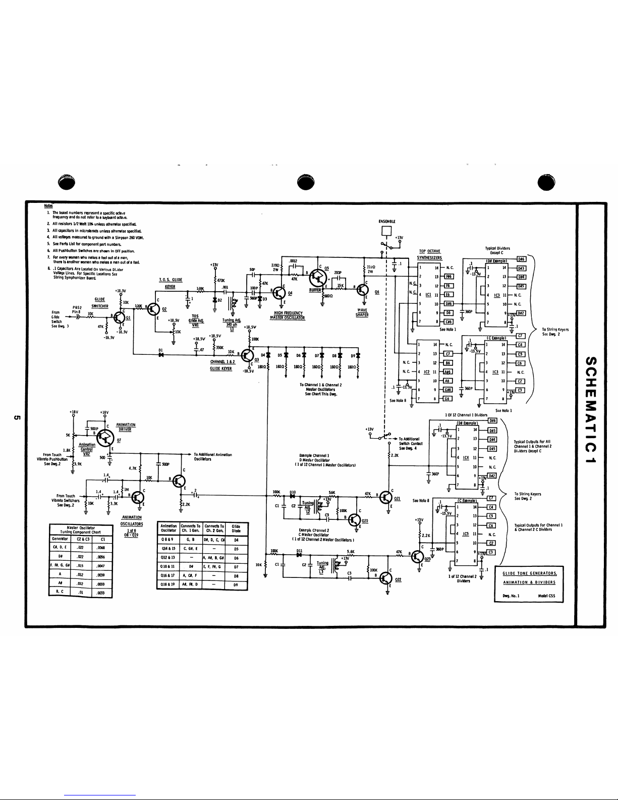
1.
The
boxed
numbers
represent a specific
octane
frequency
and
do
not
refer
to a keyboard
octa;e.
2.
All
resistors
1/2
Watt
10%
un4ess
otherwise
specified.
3.
All
capacitors
in
microfarads
unless
otherwise
specified.
4.
All
voltages
measured
to
ground
with a Simpson
260
VOM.
5.
See
Parts
List
for
component
part
numbers.
6.
All
Pushbutton
Switches
are
shown
in
OFF
position.
7.
For
every
woman
who
makes a fool
out
of a man,
there
Is
another
woman
who
makes a man
out
of a fooL
8.
.1
Capacitors
Are
Located
On
various
Oi.ider
Voltage
Lines.
For
Specific
Locations
See
String
Symphonizer
Board.
ENSEMBLE
+
18.5V
Gl5fe~Adj.
Tun
Example
Channel
1
D
Master
Oscillator
(1
of
12
Channel 1 Master
Oscillators)
Exarrpk
Channel
2
C
Vaster
Oscillator
(1
of
12
Channel 2 Master
Oscillators
I
0)
o
X
m
1.8K
From
Touch
__^
Vibrato
Pushbutton^
SeeDwg.2
From Touch
Vibrato
Switchers
See
Dwg.
2
O
1
of
6
Typical
Outputs
For
Channel
1
&
Channel 2 C
Dividers
GLIDE
TONE
GENERATORS.
ANIMATION & DIVIDERS
Dwg.
No.
1
Model
CSS
 Loading...