

Free Hot Water Freedom 5003, Freedom 5002 Installation, Operation And Maintenance Manual

_______________________________________________________________________________
SRCC OG-300 Certified Solar Water Heating System
Free Hot Water Collector 5000 Series – Freedom 5002, 5003
2011044A - Liberty - 4002 XG
2011044B - Liberty - 4003 XG
2011047A - Liberty - 4002 XE
2011047B - Liberty - 4003 XE
Type: AC Circulating Pump and Differential Control
Installation, Operation and Maintenance Manual
The solar energy system described by this manual, when properly installed and maintained, meets the minimum
standards established by the SRCC. This certification does not imply endorsement or warranty of this product by
SRCC.
Version 2011.02
_______________________________________________________________________________
Free Hot Water 2146 Bering Dr. San Jose, CA 95131 Tel: 408 218 3660 Fax 408 872 4142 www.FreeHotWater.com

Table of Contents
Safety Information ................................................................................................................................................... 3
Transport Note .................................................................................................................................................. 4
Installation, Operation And Maintenance Manual .................................................................................................. 5
Introduction ....................................................................................................................................................... 5
System Description ........................................................................................................................................... 6
Specifications .................................................................................................................................................... 6
Freeze Protection .............................................................................................................................................. 7
Tools Needed .................................................................................................................................................... 8
Collector Specifications ........................................................................................................................................... 9
Collector Certification OG100 ......................................................................................................................... 10
Pressure drop and flow rates .......................................................................................................................... 11
General Closed Loop System Schematics ....................................................................................................... 12
Precautions ..................................................................................................................................................... 14
Collector Orientation ...................................................................................................................................... 16
Installation Steps for Roof Mounting .................................................................................................................... 17
Pitched Roof Mounting ................................................................................................................................... 17
Recommend Anchor Points ............................................................................................................................ 20
Flat Roof Installation Instructions ................................................................................................................... 22
Installing the Solar Tank ........................................................................................................................................ 24
Basic plumbing connection diagram ............................................................................................................... 26
Commissioning ................................................................................................................................................ 27
Regular Care .................................................................................................................................................... 28
Anode Replacement ........................................................................................................................................ 29
Pump Station and Controller ................................................................................................................................. 34
Mounting ........................................................................................................................................................ 35
Options ............................................................................................................................................................ 36
Installing the Expansion Tank ................................................................................................................................ 38
Solar Thermal Controller ........................................................................................................................................ 39
System Pressure Guide ......................................................................................................................................... 45
Charging the System ....................................................................................................................................... 46
Propylene Glycol Material Safety Data Sheet .................................................................................................. 48
Labels .................................................................................................................................................................... 50
Systems Parts List ................................................................................................................................................. 52
Trouble Shooting .................................................................................................................................................. 53
Vacation Planning ........................................................................................................................................... 56
Maintenance Notes ........................................................................................................................................ 57
Installer Information ............................................................................................................................................. 58
Warranty & Guaranty ............................................................................................................................................ 58
Collector Warranty Certificate ............................................................................................................... 59
Page 2

Page 3

Attention: Do not lift the collectors by the connections and or the screw threads
Page 4

DOMESTIC SOLAR WATER HEATER SYSTEM
INSTALLATION, OPERATION AND MAINTENANCE MANUAL
The Free Hot Water domestic solar water heating system has gone through an extensive design, technical and
performance review by the Solar Rating & Certification Corporation (SRCC). The installation of your Free Hot Water
system is intended to be executed by properly licensed and experienced professional contractors in accordance with
SRCC Standard OG-300, "Operating Guidelines and Minimum Standards For Certifying", and must conform to
applicable federal, state and local regulations, codes, ordinances and standards governing the installation of solar
water heating systems.
The solar energy system described by this manual, when properly installed and maintained, meets the minimum
standards established by the SRCC. This certification does not imply endorsement or warranty of this product by the
SRCC. OG-300 system certification is granted to Free Hot Water by the SRCC. It may not be used for any commercial
purpose without the prior written consent of Free Hot Water. Free Hot Water must approve any deviation from the
materials and methods described in this manual in writing.
CONGRATULATIONS!
Congratulations on investing in one of the most advanced solar water heating systems available. Utilizing the free,
environmentally friendly energy from the sun to heat water for your home makes so much sense. Solar energy is
efficient, safe and reliable and your decision to use solar energy is helping to preserve our environment and to
reduce our rapid depletion of non renewable, fossil fuels.
The FREE HOT WATER solar water heating system uses the sun’s energy as a source of heat to produce hot water for
domestic household use. Designed to meet the certification requirements of SRCC 0G-300, FREE HOT WATER solar
water heating systems are reliable, and can typically generate from 50% to 80% of your annual household water
heating needs from the sun. Your remaining hot water needs can be supplied by your existing electric or gas water
heater or boiler. Results will vary based upon on your specific region in the country. Your new Free Hot Water
System uses state-of-the-art technology and will provide you with many years of maintenance free and dependable
service. If you have any questions, please feel free to contact your local dealer or our home office.
Introduction
The system performance varies as a function of the household hot water load. The ambient air temperature, the
roof pitch and orientation along with seasonal solar intensity will determine the amount of hot water generated by
your FREE HOT WATER solar water heating system.
Your FREE HOT WATER solar water heating system uses a circulation pump that circulates a propylene glycol heat
transfer fluid throughout the system. This fluid protects the collector piping from freezing, prevents corrosion of
system components, and keeps scale deposits from forming that could reduce the performance of the system.
Proper maintenance of the propylene glycol in the system can protect the solar water heating system to minus 40°
Fahrenheit. This manual is intended to familiarize you with the proper installation and maintenance of your FREE
HOT WATER solar water heating system. This system must be installed by a licensed solar or plumbing contractor in
accordance with SRCC Standard OG-300 and all applicable national, state and local codes. Failure to follow the
procedures described in this manual can void the manufacturers’ warranty.
Page 5

System Description
The FREE HOT WATER solar water heating system is a closed-loop active solar system which, when installed with a
suitable auxiliary heat source, can act as the primary source of domestic hot water for residential use. The system
components provided with the FREE HOT WATER solar water heating system include the solar collectors, collector
flashings, solar loop pipe and fittings, solar storage tank, solar pump station and controller, temperature sensors,
expansion tank, air separator, mixing valve, and non-toxic propylene glycol heat transfer fluid. The solar collector is
the engine of the FREE HOT WATER solar water heating system.
When the sun is shining, the heat energy is absorbed by the solar collector and transferred to the heat transfer fluid
circulating through the solar collectors. The system pump efficiently circulates this heated fluid through the
collector’s piping and the heat exchanger located in the solar storage tank. As the heat transfer fluid passes through
the heat exchanger, the heat in the fluid is transferred by conduction to the potable water in your solar storage tank
causing the temperature in the tank to rise. This process continues as long as the sun is shining or until the
temperature in the solar storage tanks reaches its maximum temperature set point.
General Instructions
Installation must only be carried out by qualified personnel. The entire information in these instructions is intended
exclusively for such qualified personnel. Only the supplied material should be used for the installation. Prior to starting
installation and operation of the solar collector system, please inform yourself about the applicable local standards and
regulations. The use of a carrying strap is recommended for transporting the collector. The collector must not be lifted
at the connections or on the threading. Avoid impacts and mechanical influences on the collector, in particular on the
solar glass, the rear panel and pipe connections.
The collectors may only be mounted on sufficiently load-bearing roof surfaces and substructures. It is imperative that
the static load bearing capacity of the roof or substructure is checked in terms of local and regional conditions prior to
installation of the collectors by the customer, if necessary through the involvement of a structural engineer.
Particular attention should be paid to the quality of the (timber) substructure in terms of the stability of the screw
connections necessary for fastening the collectors.
Specifications
The FREE HOT WATER solar water heating system is designed to produce domestic hot water from either solar
collector, an electrical or gas backup, or a boiler back up (provided by others). The FREE HOT WATER systems can
also be used as a solar preheat system to conventional electric or gas water heaters (provided by others).
Collectors and flashings
FREE HOT WATER solar collectors and flashings allow for a low profile, roof integrated, solar panel installation. The
FREE HOT WATER collector is made up of copper tubes and a plate that is covered with a highly selective absorber
coating; this assembly is enclosed in a well insulated aluminum frame or “box” and covered with low-iron tempered
glass glazing. FREE HOT WATER solar water heating systems are available for integration onto either shingle or tile
roofs. The collector is suitable for angles between 15° (minimum) and 75° (maximum). The collector connections
and the ventilation openings must be protected against the penetration of water as well as against contamination
through dust etc.
Page 6

Solar Storage Tank
All FREE HOT WATER solar water heating systems will include a solar storage tank with the solar heat exchanger
located in the bottom section of the tank to heat the entire water volume of the tank. The tank contains a
thermometer located on the outside of the tank so you will know the temperature in the tank.
Collector Loop Piping
FREE HOT WATER solar water heating systems are designed for use with copper pipe or pre-insulated corrugated
stainless steel flexible piping. No other piping may be substituted for use in the solar loop. Collector piping
installation requires the use of copper and brass fittings in the collector loop. Piping in new solar installations may
have dirt, grease, or other impurities that over time affect the quality of the propylene glycol heat transfer fluid. A
thorough cleaning is required before charging the system with glycol. All vertical piping between the storage tank
and the collector shall be supported at each story or at maximum intervals of ten feet (10’) using pipe hangers. If
additional supports are needed, copper plumbers tape or tube strap may be used. The pipe insulation may not be
compressed or crimped by the strapping material.
The installation of all horizontal and vertical piping may not reduce the performance or rating of any structural
member or fire rated assembly. Adhere to all applicable local codes and ordinances.
The collector loop cold supply and hot return lines must be well insulated with the high quality flexible closed cell
insulation to minimize heat loss. There shall be no exposed piping or fittings. The wall thickness of the pipe
insulation should not be less than ¾”. Any above ground exterior pipe insulation that may be subject to UV
degradation must be wrapped with foil tape or painted with two coats of high quality water-based acrylic resin
coating.
Pump Station Controller
All FREE HOT WATER solar water heating systems include a pump station controller that include the temperature
and pressure gauges, pressure relief valve, check valves, ball valves, fill and drain valves, and differential controller
required to properly operate the FREE HOT WATER solar water heating system. The system temperatures for the
collector and storage tank can be read from the differential controller. Typical tank operating temperatures can
range from the cold supply of 40°-80° F up to 180° F which represents the high limit of the tank. This will vary
depending on the climate where the system is installed. The collector temperature sensor should be 5°-20° F above
the tank sensor during normal operation. During idle periods, when there is no sun, the collector will read the
ambient temperature and when there is full sun upward to 250° F.
Balance of Systems
The balance of components in all FREE HOT WATER solar water heating systems: solar loop pipe and fittings,
temperature sensors, expansion tank, air separator, mixing valve, and non-toxic propylene glycol heat transfer fluid
components carry temperature and pressure ratings required of the FREE HOT WATER solar water heating system
design.
Freeze Protection
The FREE HOT WATER solar water heating system can be operated down to ambient temperatures of –40°F using
proper concentrations of propylene glycol. Freeze tolerance limits are based upon an assumed set of environmental
conditions. Refer to the propylene glycol specification sheet under the “Flushing and filling” section of this manual
for recommended concentration of propylene glycol and distilled water to provide adequate freeze protection in
your specific climate. The differential controller uses temperature sensors to monitor the temperature difference
between the collector and the solar storage tank. The controller turns on when the collector is 20° F above tank
Page 7

temperature and turns off when the differential drops below 10° F. HOUGHTON CHEMICAL CORPORATION “ECONOTHERM” ” and “Safe-T-Therm” propylene glycol heat transfer fluid shall be used in this system as the primary freeze
protection agent. Unauthorized fluid substitutions can result in a threat to health, welfare and safety and may cause
the system piping to freeze.
All component warranties express or implied, are voided if uninhibited glycol, potable or distilled water are
substituted for the specified heat transfer fluid described in this manual, or if the heat transfer fluid is not
maintained in accordance with the manufacturer’s instructions.
Freeze tolerance limits are based upon an assumed set of environmental conditions. Extended periods of cold
weather, including ambient air temperatures above the specified limit may cause freezing in exposed parts of the
system. It is the owner’s responsibility to protect the system in accordance with Free Hot Water’s instructions if the
ambient air temperature approaches the specified freeze tolerance limit.
Legal Guarantee
Legal guarantee claims can only be made if the supplier's own antifreeze has been used and maintenance has been
carried out correctly. Installation by qualified personnel with absolute adherence to the instructions is a prerequisite
for the justification of claims.
Tools Needed
Page 8

Collector Specifications
High Performance Thermal Collector
Intelligent Design Deep Drawn Aluminum Tray
Selective Absorbent Coating
Thermal Insulation Rockwool
Tempered Low Iron Glass
Suitable for Closed & Open Loop Systems
Pitched and Flat Roof Installation Systems
Dimensions - 79.5 X 40 X 3
Thermal Output –1.35 Kw per hour
Max Stagnation (f) 410 Max PSI-116
Absorber Capacity 1.1 gal.
Manifold 3/4 - Risers 3/8
Free Hot Water item #: FHWC-FC-50221
Gross Area: 2.070 m2, 22.28 sf
Net Aperture: 1.85 m2, 19.91 sf
Recommended Tilt Angle 5-60 degrees
Weight - 84 Lbs
10 Year Limited Warranty
Approvals - SRCC OG 100
SRCC Daily BTU's - 23,100
Page 9

Page 10
Collectors
Up to 6
Up to 13
Up to 22
Up to 45
Pipe Diameter (inch)
½”
¾”
1”
1-¼”
Flow Rate (kg/h)
50
100
150
200
250
300
350
400
450
Pressure Loss (mbar)
1.7
4.1
7.3
11.2
15.8
21.1
27.1
33.9
41.4
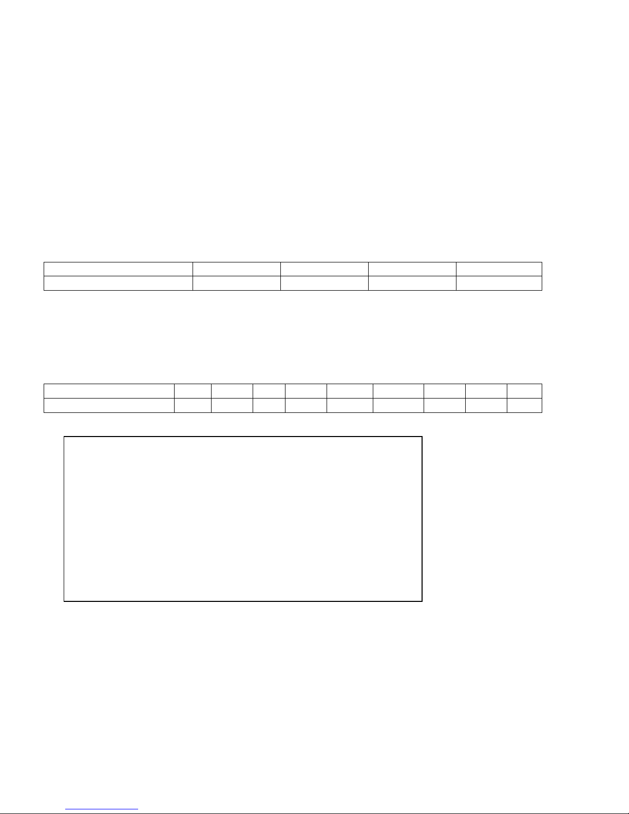
Pressure drop and flow rates
Mass flow rate
To ensure the performance of the collector, a specific flow rate of .5 gallons per minute is to be selected
up to a collector panel size of approximately 27 sq. ft.
Pipe diameters
Dimensions table with a specific flow rate of .5 gallons per minute
Pressure loss collector for anti-freeze / water mixture (40% / 60%) at a thermal conducting temperature
of 122° F.
Pressure loss curve: �p = 0,0001443x² + 0,0270143x
Pressure loss collector for anti-freeze / water mixture (40% / 60%), Temperature of 122° F
Page 11

Page 12

Page 13
Precautions
For safety reasons you should only fill the collectors when there is no direct irradiation from the sun (covering the
collectors can be an option). Especially in regions exposed to frost, for flat plate collectors you should use a mixture
of anti freeze with water (40% anti freeze). The solar thermal system should be filled and commissioned within one
week of installation, because heat build-up in the collector array can damage the flat gaskets in empty systems. If
this is not possible, the flat gaskets should be replaced before commissioning to prevent leakage.
Attention : Anti freeze that is not premixed must be mixed with water prior to charging the system
Recommended antifreeze for flat plate collectors – FHWM-GY-50005
25% antifreeze / 75% water mix - freeze point 14°F
40% antifreeze / 60% water mix - freeze point -5°F
50% antifreeze / 50% water mix - freeze point -25°F
It may not be possible to completely empty collectors one they have been filled. For this reason collectors exposed
to frost should only be filled with a distilled water/antifreeze mixture, also for pressure and function tests.
Alternatively, the pressure test can also be carried out using compressed air and leak detection spray.
Installing the temperature sensor
The temperature sensor should be installed in the sensor sleeve nearest to the collector array flow. To ensure
optimal contact between the sensor and the surrounding environment, the gap between the sensor sleeve and the
sensor element should be filled with a suitable conducting compound. All materials used for installing temperature
sensors (sensor element, conducting compound, cables, sealing and insulating materials) must be suitably
temperature resistant (up to 482° F).
Operating pressure: The maximum operating pressure is 145 psi.
Bleeding
The system must be bled:
- When commissioning the system (after filling the collectors)
- 4 weeks after commissioning
- When necessary, e.g. if there are malfunctions
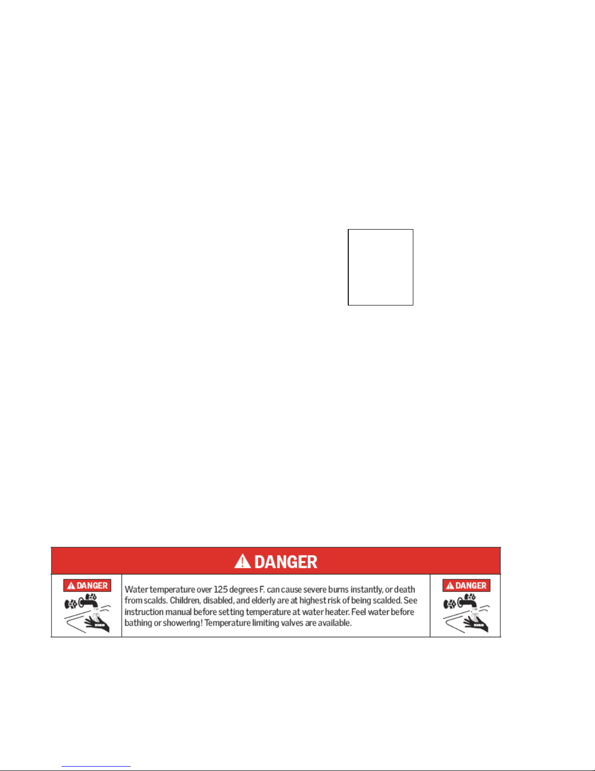
Warning: Risk of scalding due to steam and hot heat transfer fluid!
Page 14

Only operate the bleeding valve if the temperature of the heat transfer fluid is < 140° F.
When bleeding the system, the collectors must not be hot! Cover the collectors and, if possible, bleed the system in
the morning.
See Material Safety Data Sheet on page 45 for safety information.
Check heat transfer fluid
The heat transfer fluid must be checked every two years with regard to its antifreeze and pH value.
- Check antifreeze using antifreeze tester and replace or refill if necessary!
Target value is ca. - 77° F and - 22° F depending on climatic conditions.
- Check pH value with a pH indicator rod (target value approx. pH 7.5):
If the limit pH value is less than ≤ pH 7, replace the heat transfer fluid.
Maintenance of the collector
The collector or the collector array must be inspected visually, once a year, for any damage, leaks and
contamination. Additional recommendations on operation and maintenance can be found in the supplier's general
documentation and instructions on commissioning and maintenance.
Connecting the collectors to one another
The collectors must be connected to one another and/or to the connection pipes using the supplied connectors.
When tightening the union nuts and/or compression fittings, always balance (counter) the torque* with a pipe wrench
or another spanner to prevent damage to the absorber.
Do not run the solar collector(s) without a Pressure Relief Valve, safety valve in the system to avoid over pressure in
the solar circuit.
Warning: Freeze tolerance limits are based upon an assumed set of environmental conditions.
Warning: If the freezing point of the fluid in an exposed part of the system is above the freeze tolerance
limit specified for the system: Extended period of cold weather, including ambient air temperatures
above the specified limit, may cause freezing in exposed parts of the system. It is the owner’s
responsibility to protect the system in accordance with the Supplier’s instructions if the air temperature is
anticipated to approach the specified freeze tolerance limit.
Page 15
Solar Collector Orientation
Operating your Free Hot Water solar water heater for optimal efficiency is based on the correct orientation, pitch,
and location of the solar collectors. In North America, collectors should be oriented due south, however may be
oriented up to 45 degrees east or west of due south with minimal losses in solar gain. Optimal pitch is +/– 10° from
the latitude of the installation site.
Free Hot Water solar collectors must be installed at a minimum pitch of 15 degrees from horizontal, and for optimal
performance, the recommended pitch is between 15–60 degrees. The collector should be mounted as close to the
storage tank as possible to minimize heat loss in the piping runs. The solar collector must be located in an area of
the roof that will be un-shaded for the majority of the day (from 9:00–3:00) all year round. Adjacent buildings and
trees should be checked for possible winter shading.
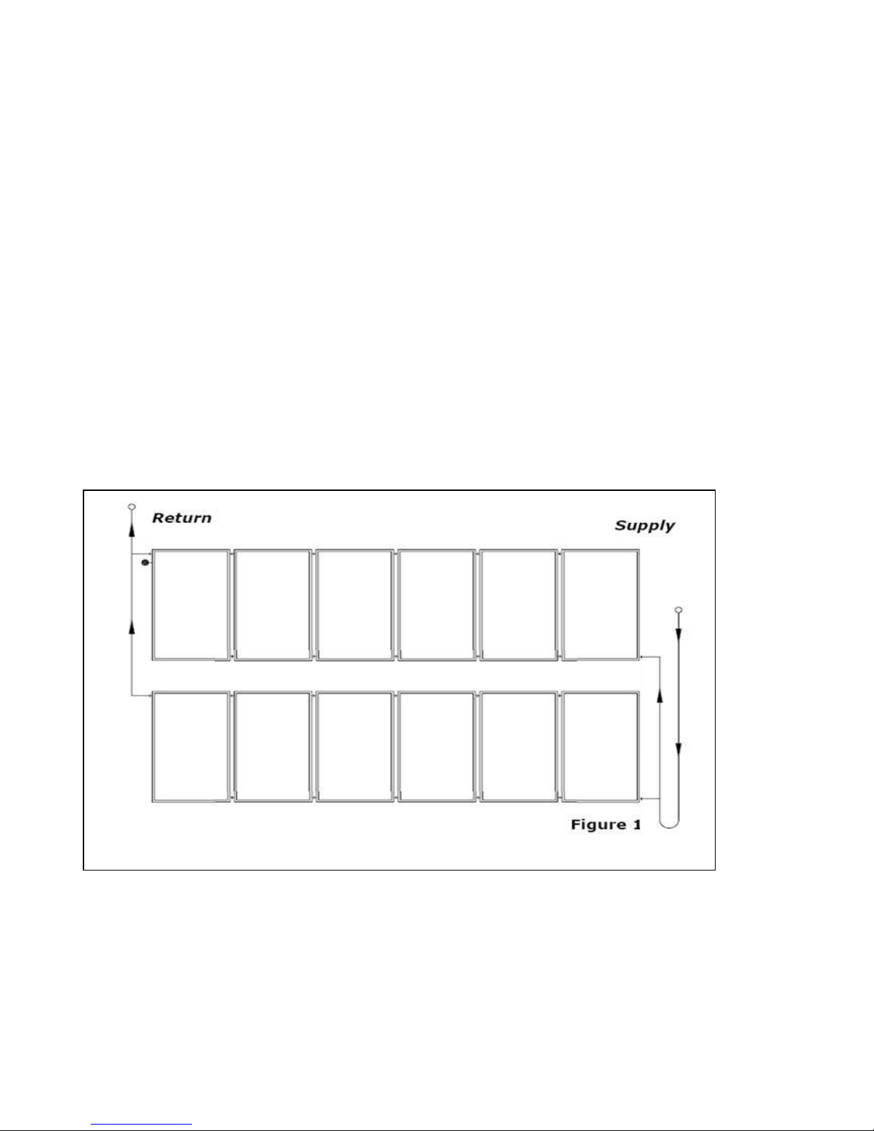
The following diagram below is an example of how the collectors can be connected to one another. However, the
actual connection may be different depending on structural conditions. A maximum of 6 collectors may be
connected in a series! If a collector panel is made up of more than 6 collectors, the panel must be connected several
times in parallel
Page 16
Installation Steps for Pitched Roof Mounting
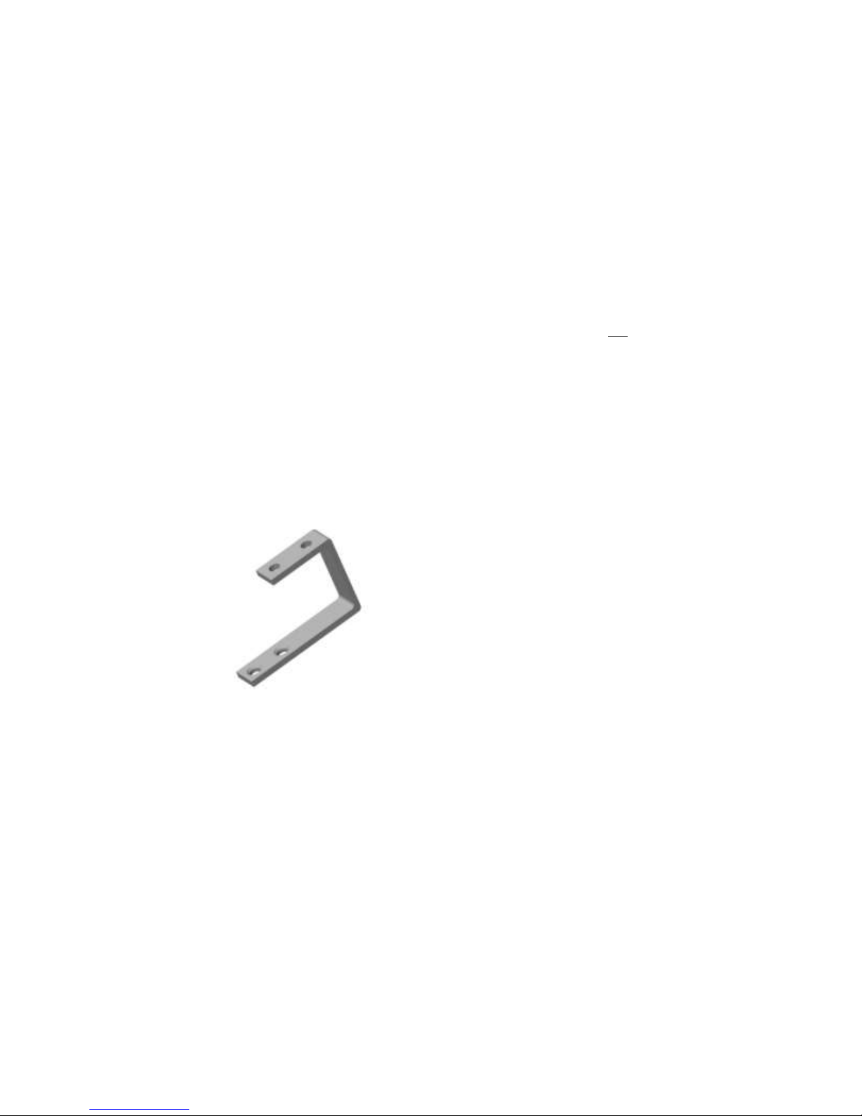
1. Locate and mark the roof rafters into which the solar collector mounting brackets will be mounted
(one way to find rafters is to see the “tails” at the edge of the roof).
2. To create a set point for plumbing and level installation, measure the distance from the edge of the
roof to the desired mounting points and mark the points where the collector mounting brackets will be
installed (fig 1.2).
*Note: you need to install a screw into one of the holes in the mounting bracket, not both holes (fig
1.1).
* Note: for collector model 7000 upper and lower mounting bracket should be 78” apart measured
from top of top bracket to bottom of bottom bracket.
* Note: both the bottom and the top mounting brackets should be placed as per figure 2.0 from each
other as possible in the width dimension.
Fig 1.1 Fig 1.2
3. Determine where penetration will be to connect the solar hot water collector with the storage tank
and/or the water supply (use 2 pre-insulated ¾” steel flex hoses or 2 insulated ¾” copper pipes for
that connection).
Note: *For a two-collector system that will be elevated above the roof surface, a good location for this
penetration is directly between the two collectors.
4. Holes should be slightly overlapping to form a sideways “8” shape (see illustration 1.3). Mark the
penetration before making holes. If you are installing on a composition shingle roof make holes 5”
below the bottom of the shingle above the penetration.
Page 17

Fig 1.3
5. Using a hole saw, cut the hole (penetration) for the 2 hoses or pipes from step 3.
6. If using flex hose: before connecting the hose, measure, cut, and lay out the hose, including enough
length for 8’ of hose above the roof. Pull the hose through the hole.
7. Begin mounting bracket installation with bottom bracket. Mark a straight chalk line between the 2
bottom bracket mounting points.
8. For composition shingle roof, DO NOT PENETRATE THE COMPOSITION SHINGLE. Before installing
9. Next, using a cutting tool, cut out a piece of the roof material beneath the top layer of the composition
Page 18
Fig 1.4
screws, lift the composition shingle at the install point and slide the mounting bracket in, beneath the
top composition shingle. Place the bracket so that the top surface composition shingle clears the
bracket when folded (lifted) up or down and mark an outline of the mounting bracket where the
mounting bracket will be fastened to the roof rafter or other appropriate mounting substrate. The
marked area should be 1.5” wide and 2.5” high.
shingle (the top layer will NOT be penetrated for the mounting brackets) as marked 1.5” X 2.5” in the
shape of the mounting bracket.
Cutting out a piece of roofing material will provide for a flush-mounted roofing bracket.
 Loading...