

Page 1
Multi-Piece Sectional Product
Marketing Materials
Product Sheets
Pricing
www.freedomshowers.com
Tools/materials you might need for proper installation
• hammer
• drill with phillips screw bit
• 1/2” notched trowel
• 1/8” drill bit
• spatula
• grease pencil (china marker)
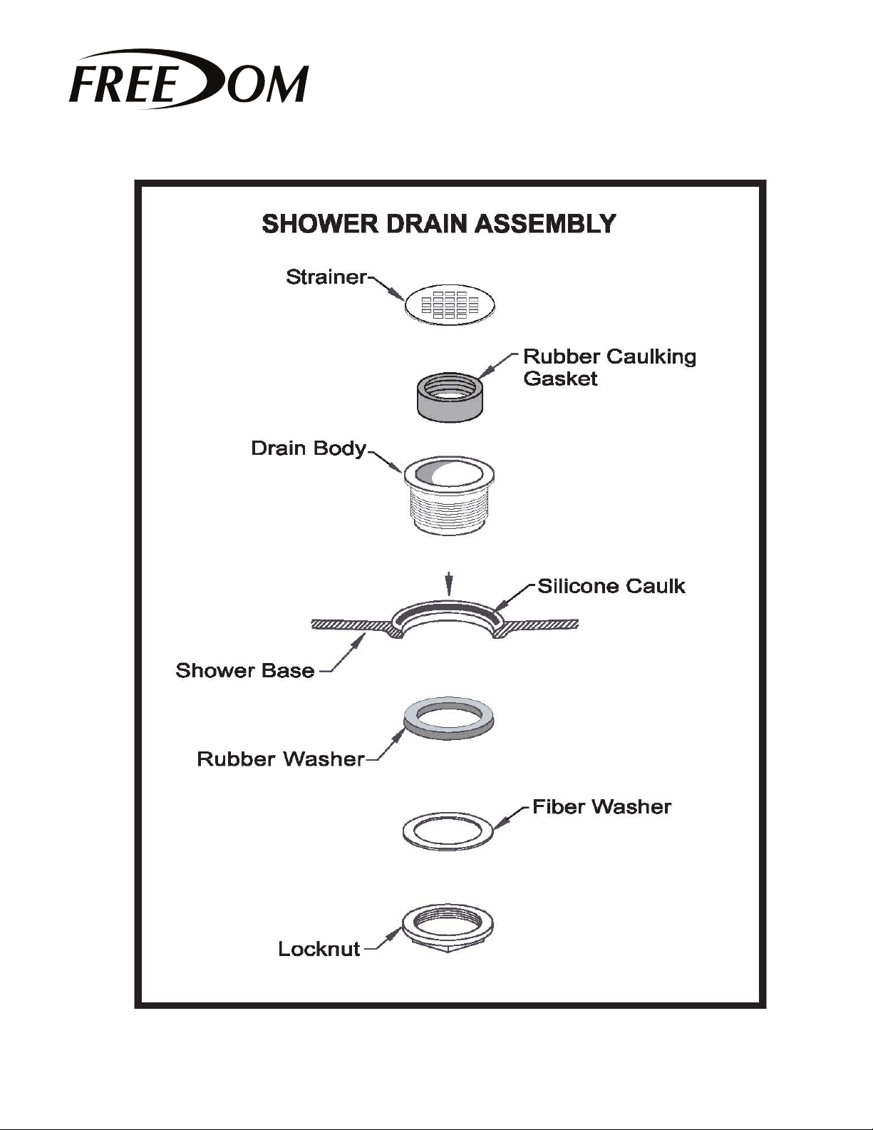
• auger mixing tool for drill
• caulking gun
• 4’ level
• 2’ level
• nails
• (50+) 1 1/4” wood screws
For best results, please read and follow all directions
carefully.
1. Avoid exposure to weather. Product carton is not
waterproof. Carton exposed to rain or snow may result in
accumulated water penetrating the back laminates of the
shower pan and soak the glassed in reinforcement supports
causing bulges in the applied acrylic surface.
2. Most handling damage is the result of impact blows to
the back of the berglass units.
3. Never drag this berglass product on any surface. Always
carry the pan or use a two wheel dolly.
4. Never drop the berglass shower pan from any height,
not even an inch or stress cracks are likely to occur.
5. Placing objects inside the unit can cause scratches or nicks
to the nished surface. Do not use the shower pan as a
trash receptacle! Always place a drop cloth or cardboard on
the oor when working inside the shower.
6. Never clean applied acrylic surface with metal tools of
any kind, including razor blades.
PLANNING YOUR INSTALLATION
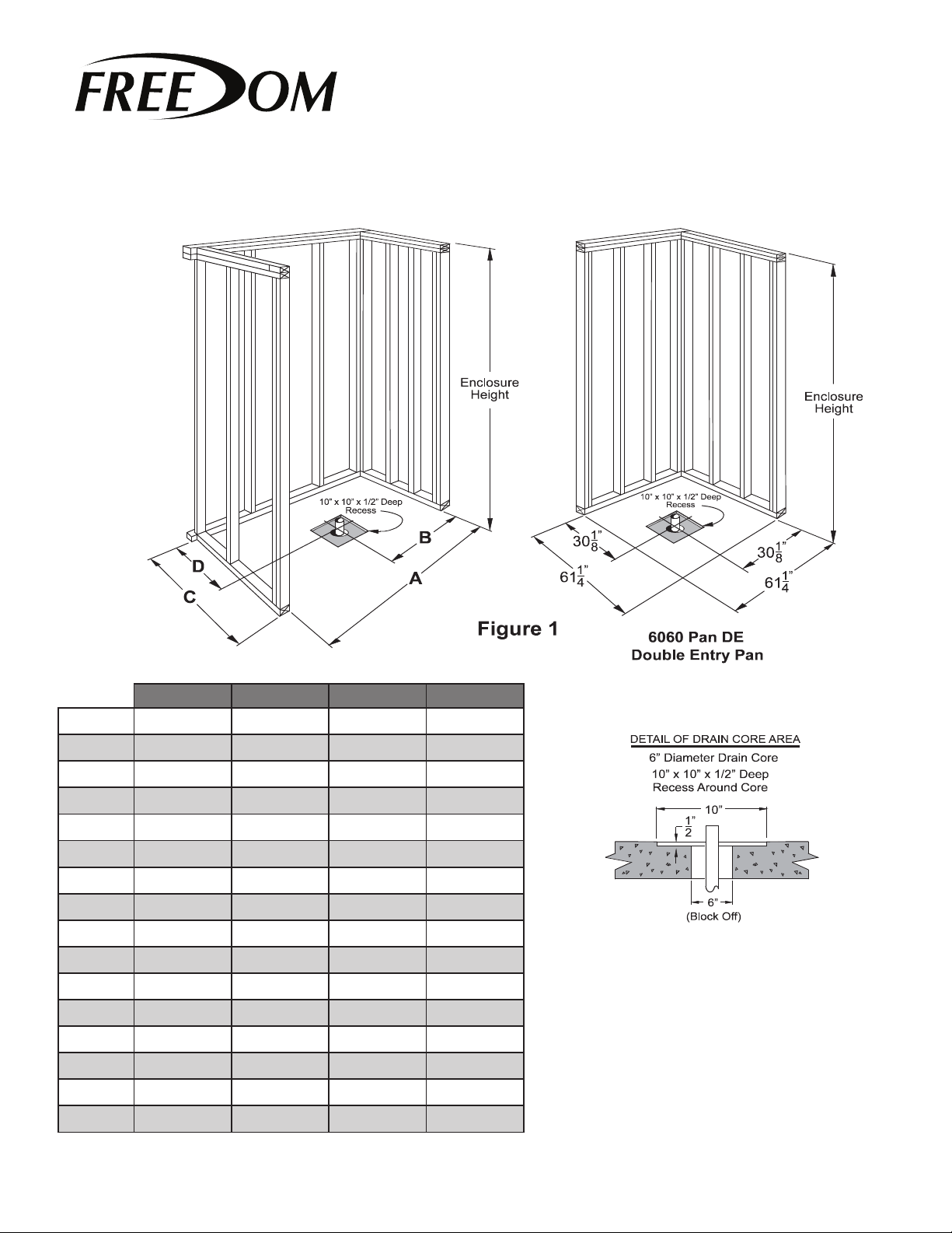
1. Review the Framing Diagrams in Figure 1. Modify existing
framing if required. For new construction, build framing
structure in accordance with product dimensions and notes
shown in the Framing Diagrams. The two wall Framing
Diagram is for the 6060 3P two wall shower only.
BRIEF OVERVIEW
Please read instructions before beginning the installation.
Note: Unit will not install properly if framing pocket is not
square and of proper size. The dimensions shown in the
• solid wood ooring adhesive or 100%
• two gallons of water - for mixing
• tube of white bathroom caulking
• (2) tubes of 100% clear silicone
• (3) 8’ 2x4s
• (1) 8” long 2x4
• (1) 24” long 2x4
silicone adhesive - (2) one gallon
buckets per shower
bedding compound and water test
around drain
caulking
FRAMING DIAGRAMS are 1/4” larger than the size of the
shower. This product is manufactured to tight specications.
The 1/4” over sizing is for maneuvering and installation ease. If
1/4” over is not reasonable, sizing closer to the product actual
dimensions is allowable.
When trial tting the shower, use a level to conrm the parts
are level and plumb. If any gaps are present between the
shower and framing, use furring strips to ll the gaps. If the
walls and oor are not level, there may be an excessive gap
at the seams. The unit is designed to allow an 1/8” gap at the
seams.
2. The shower base will be installed, leveled, and fastened to
the framing before the walls are installed. It is essential the
framing pocket be square and plumb for the unit to install
properly. The oor also must have no voids or out of level
conditions. If these are present, they must be corrected
before installation. Floor leveling compound can be
purchased at a local home improvement store. Make sure
the area is completely dry.
3. Following the shower pan installation, place the back wall
sections, then the side walls. The par ts are indexed to one
another by a slot and pin connection system. The parts are
pushed tight together before connection to the framing
pocket is made. To have a successful installation, two persons
are required.
4. Plan for the location of the shower water control valve.
Note if planning to install the control valve in the back wall of
the shower with a two piece back wall, consider the location
of the seam in the wall. The control valve must be located at
a height where the seam and mounting ange do not cause
a conict with placement of the control valve, or water supply
lines. These considerations are not necessary if installing on
the one piece back wall, or side wall. Plan for routing the water
supply lines to the control valve installation location.
Installation Instructions
• (2) large wiping cloths
• self-caulking shower drain tting
• Epoxy - for optional EasyBase™
installation
For INSTALLATION USING
EPOXY ADHESIVE refer to last
page of instructions.
Page 2
Multi-Piece Sectional Product
Marketing Materials
Product Sheets
Pricing
3
FRAMING DIAGRAMS
C
C
A B
C D
38 7/8”
48 1/4”
60 1/4”
60 1/4”
60 1/4”
60 1/4”
60 1/4”
60 1/4”
60 1/4”
60 1/4”
62 5/8”
62 5/8”
62 5/8” 38 1/2” 19 3/8”
31 5/16”
32 1/2” 16 3/8”
30 1/8” 61 1/4” 30 1/8”
30 1/8”
49 1/4”
24 1/8”
8 9/16”
37 1/8”
18 3/4”
8 9/16”
30 1/8” 37 1/4”
18 1/8”
33 5/8” 15 3/8”
30 1/8” 33 5/8” 15 1/8”
8 9/16” 31 1/4”
15 1/8”
30 1/8”
31 1/4”
15 1/8”
24 1/8”
37 1/4”
18 1/8”
19 7/16”
38 5/8”
19 1/8”
50 1/4” 25 1/8” 50 1/8” 25”
54 1/4” 8 5/8” 31” 15”
54 1/4” 8 5/8” 36 7/8” 18 5/8”
www.freedomshowers.com
Installation Instructions
FRAMING DIAGRAMS
A B C D
3838
3838
4836
4836
6030
5050
6030 L-R
5430 LR
6033 C
5436 LR
6033 L-R
6030 C
6036
6030 LR
6036 L-R
6048
6033 C
6060
6033 LR
6036 C
6036 LR
6048
6060
6232 C
6232 LR
6238
38 7/8” 19 7/16” 38 5/8” 19 1/8”
48 1/4” 24 1/8” 37 1/4” 18 1/8”
C
50 1/4” 25 1/8” 50 1/8” 25”
54 1/4” 8 5/8” 31” 15”
54 1/4” 8 5/8” 36 7/8” 17 5/8”
60 1/4” 30 1/8” 31 1/4” 15 1/8”
C
60 1/4” 8 9/16” 31 1/4” 15 1/8”
60 1/4” 30 1/8” 33 5/8” 15 1/2”
60 1/4” 8 9/16” 33 5/8” 15 3/8”
6232
60 1/4” 30 1/8” 37 1/4” 18 1/8”
6238
60 1/4” 8 9/16” 37 1/8” 18 3/4”
5050
60 1/4” 30 1/8” 49 1/4” 24 1/8”
5430
60 1/4” 30 1/8” 61 1/4” 30 1/8”
5436
62 5/8” 31 5/16” 32 1/2” 16 3/8”
62 11/16” 8 9/16” 32 1/4” 16”
62 5/8” 62 5/8” 38 1/2” 19 3/8”
A B
38 7/8”
48 1/4”
60 1/4”
60 1/4”
60 1/4”
60 1/4”
60 1/4”
60 1/4”
60 1/4”
60 1/4”
62 5/8”
62 5/8”
50 1/4” 25 1/8” 50 1/8” 25”
54 1/4” 8 5/8” 31” 15”
54 1/4” 8 5/8” 36 7/8” 18 5/8”
19 7/16”
24 1/8”
30 1/8”
8 9/16” 31 1/4”
30 1/8” 33 5/8” 15 1/8”
8 9/16”
30 1/8” 37 1/4”
8 9/16”
30 1/8”
30 1/8” 61 1/4” 30 1/8”
31 5/16”
62 5/8” 38 1/2” 19 3/8”
C D
38 5/8”
37 1/4”
31 1/4”
33 5/8” 15 3/8”
37 1/8”
49 1/4”
32 1/2” 16 3/8”
19 1/8”
18 1/8”
15 1/8”
15 1/8”
18 1/8”
18 3/4”
24 1/8”
Note: Unit will not install properly if framing pocket is not
square and of proper size. The dimensions shown in the
FRAMING DIAGRAMS are 1/4” larger than the size of the
shower pan. This product is manufactured to tight
specifications. The 1/4” over sizing is for manuvering and
installation ease. If 1/4” over is not reasonable, sizing closer
to the product actual dimensions is allowable.
Page 3
Multi-Piece Sectional Product
Marketing Materials
Product Sheets
Pricing
www.freedomshowers.com
5. In the installation location, the drain opening in the oor
should have a 6” core for the drain pipe, and a 10” x 10” x 1/2”
deep recess in the sub oor. (The drain core must be blocked
when lled with Thin-Set or 100% silicone adhesive). The 10” x
10” x 1/2” deep recess is required to assure proper drainage.
See Detail of Drain Core Area
6. Check the outside of the package for visible shipping
damage. If damage is noted, contact your supplier before
proceeding with the installation.
7. Locate accessories if any were ordered. They will be
packaged in the pan box. Remove those and store them in a
safe location for easy retrieval.
8. Identify each package and its contents. The label on the box
is clearly marked indicating a shower pan and wall panels.
Installation Instructions
Figure 2A
Figure 2B
INSTALLATION INSTRUCTIONS
1. Prepare the installation area by sweeping the area
completely clean.
2. Framing pocket must be sized according to the information
provided in the Framing Diagram. It is recommended that
the front studs at each side be doubled for added strength.
Framing must be extremely square and plumb in order to
accomplish a successful installation.
3. Install hot and cold water supply lines with the control valve.
Mount to the framing.
4. It is extremely important that the oor area intended for
the installation be at and level. Any areas over 1/8” out-of-
level will prevent the installation from being successful. If an
area out more than 1/8” is found, oat the oor area with a
oor leveling compound. This material must be placed and
cured (dry) before proceeding with the shower installation.
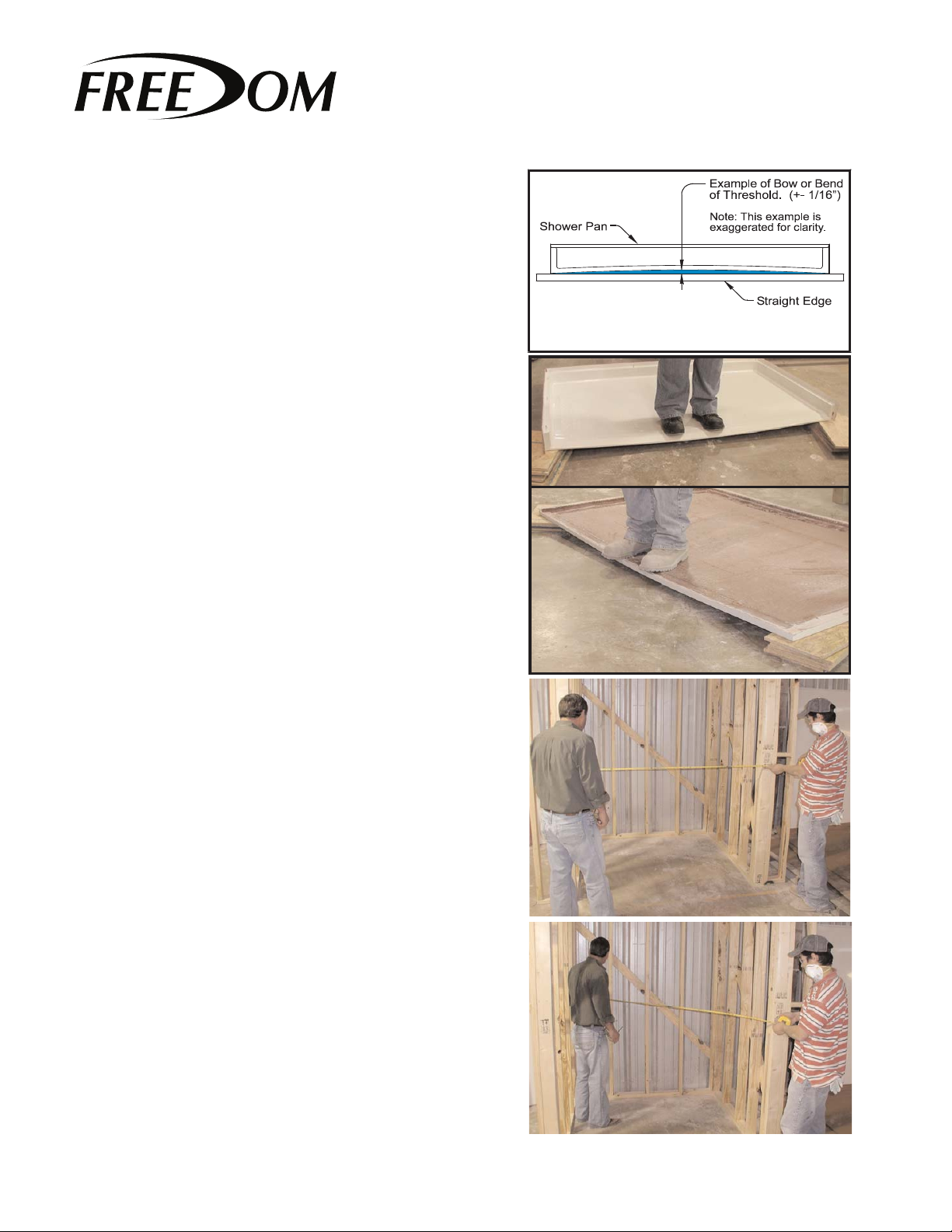
5. A special note: During handling and transport, the product
may be slightly bent. It is very important that the seam side of
each wall, and the threshold of the pan does not have any bow or
bend. This product is engineered with materials that allow for the
sections to be pressed back to the normal and straight factory
form that is intended.
As each section is removed from the packaging, use a straight
edge to check the straightness of the wall sections and of the
threshold. An example of checking the threshold is illustrated
Figure 2C
Figure 3
Figure 4
Page 4
Multi-Piece Sectional Product
Marketing Materials
Product Sheets
Pricing
www.freedomshowers.com
in Figure 2A. Check all the parts, and if not straight, follow
the procedures outlined below to bring the parts back into
the intended condition.
In the event they are not straight to 1/16”, pressure can be
applied to the top side of the material. This can be
accomplished by placing blocks under the two extreme
corners.
Always place a soft rag on the nished surface where it
contacts the wood blocks, and under your feet to avoid
damaging the nish.
Gently step on this area and allow your body weight
(Up to 250 pounds), to ex the material back straight.
Conrm straightness, repeat if necessary until +/- 1/16”
is accomplished. Figures 2B and 2C
A complete dry t for the shower base and walls is
recommended. A dry t in this instance is dened as
securing the sections to the studs with no silicone and
minimal screws to conrm a good t, and the framing
accommodates the sections. To achieve a dry t installation,
proceed with steps 6 through 23 without using the silicone,
oor adhesive and minimal screws to secure to the
framework.
Installation Instructions
Figure 5
Figure 6
Once the dry t has been done and the t conrmed,
disassemble the components. Resume step 5 and follow
each step carefully.
6. Carefully measure the framing pocket to assure it is of
proper size for the unit to be installed. Refer to dimensional
information in the Framing Diagrams in Figure 1.
Figure 7
7. Check the framing pocket for square. Check to assure
the vertical studs are plumb. To have tight seams where
the parts meet, it is very important that the framing pocket
be exceptionally square and plumb.
Check for square by holding a measuring tape from the
back left corner to the front right corner, as shown in
Figure 4. Repeat for the other side. If both dimensions are
the same, the framing is square. Adjust if necessary.
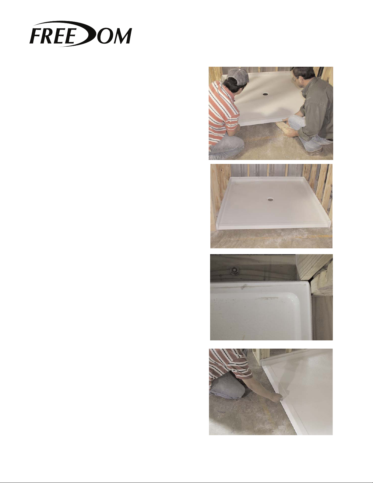
8. The next step is to dry t the shower pan to the studs
and conrm the drain location.
The better t of the pan, the better all wall parts will
assemble as intended with minimal gaps at the seams.
Figure 8
Page 5
Multi-Piece Sectional Product
Marketing Materials
Product Sheets
Pricing
www.freedomshowers.com
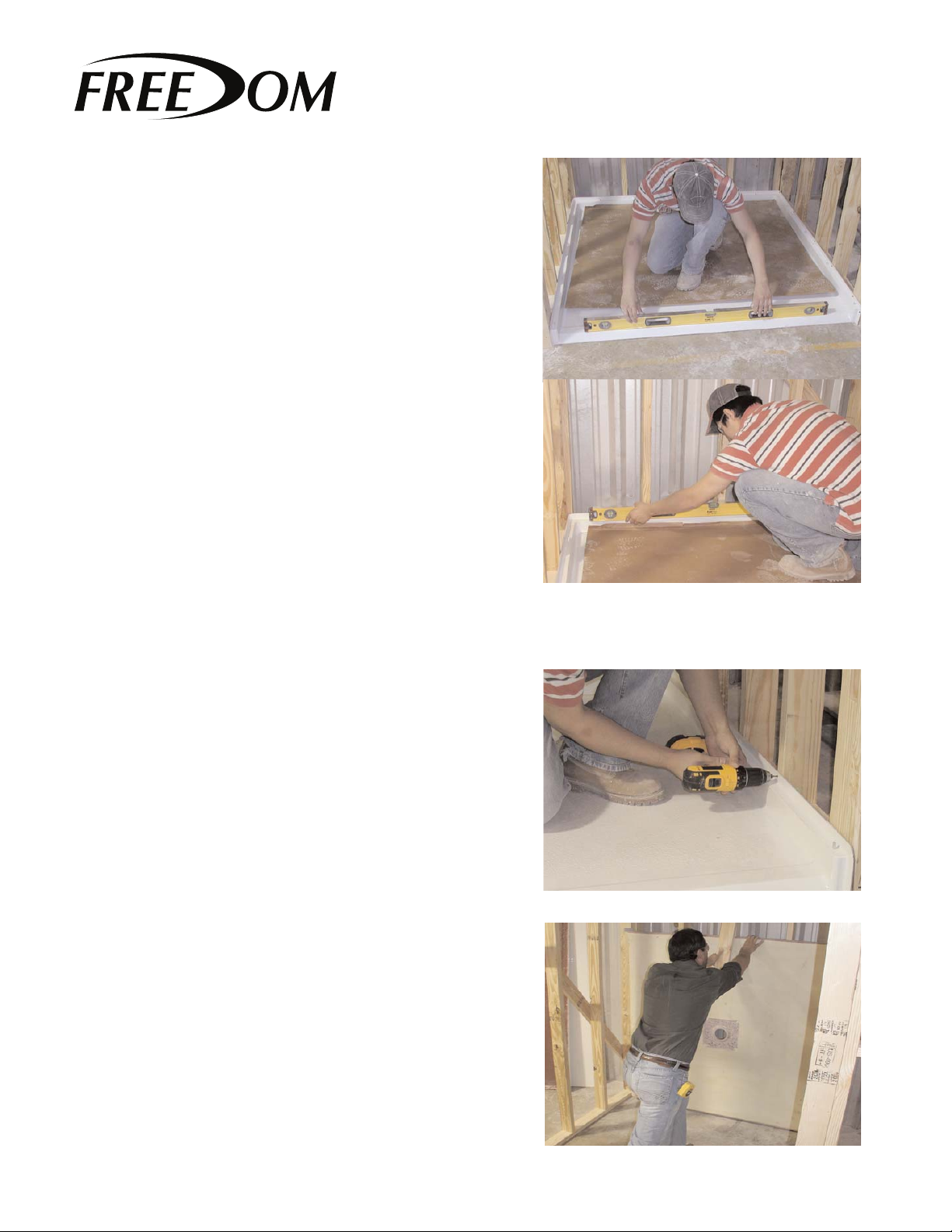
Note in Figure 5 the two installers have placed the shower
pan on the oor, and are pushing it into the installed position.
One of the installers is using a short piece of 2 x 4 wood to
hold the front of the shower pan off the oor. This will assist
in moving the pan into the installed position while preventing
chipping the front edge if it were to slide along the sub oor.
After the pan is set, ll any gaps between the mounting
ange and the framing with wood shims or furring strips to
achieve solid contact. The ange must be in contact with
the studs along all sides.
The back corners of the shower pan should be in
contact with the framing, as seen in Figure 7. Shim these
areas if required.
9. Once the shower pan is put into place and t is
conrmed, draw a pencil line on the sub oor indicating the
front point of the threshold of the pan. See Figure 8
Installation Instructions
Figure 9A
Figure 9B
Place a piece of cardboard in the oor of the shower to
protect the oor during the additional steps of installation.
There is a cut out for this on the pan box.
10. Conrm the pan is level by using a long level on top of
the threshold, and along the sides and back.
Note the level is used on the same horizontal surface that
has the pins. This will be important to allow the wall panels
to t correctly. See Figures 9A and 9B
If the pan is not level, shim the appropriate areas to achieve
level. Do not shim more than 1/8”. If shimming over 1/8” is
required, remove the pan and correct the sub-oor area by
“oating” a oor leveling compound.
11. Drill holes through the mounting anges into each
framing stud. These holes should be drilled using a
1/8” drill bit. See Figure 10
Note: Plan on using at or pan head screws to secure the
shower pan. An 1/8” gap is provided in the shower design
to account for the screw heads. This gap will allow clearance
so the walls may assembled to the shower pan.
12. The next step is to permanently install the shower
pan. A helpful tip to make this easier is to rotate the pan
upward and lean against the back framing studs of the
Figure 10
Figure 11
Page 6
Multi-Piece Sectional Product
Marketing Materials
Product Sheets
Pricing
www.freedomshowers.com
pocket. This will remove the pan from the work zone
without removing it from the stud pocket. Do not
secure the pan to the studs at this point because you
may need to reach around the pan as you install the
drain tting detailed in the next step. Make sure pan is
angled enough so it will not fall.
IF USING EPOXY ADHESIVE
refer to last page of instructions
13. Install the drain tting on the shower pan. Apply
a bead of 100% silicone caulking around the recessed
molded drain area on the nished side of the pan.
Remove the nut and all gaskets from the drain body.
Slip the threaded shank of the drain body through the
hole. Follow the instructions provided with the drain
tting to install the gaskets in the proper location. When
all gaskets and locknut are in place on the bottom side
of the shower, tighten the nut to secure the shower
drain assembly. From the top side of the drain assembly,
remove the rubber caulking gasket located on the
inside of the drain tting. This will allow the drain pipe
to slip through the drain tting on the shower.
Installation Instructions
Figure 12
A diagram of a typical drain assembly is shown in this
manual.
Wipe away any excess caulking that may have squeezed
out on the inside of the pan.
Now secure the pan in the upright position to the
back framing. Use a piece of scrap 2 x 4 lumber to
temporarily secure it. See the example in Figure 12.
14. A solid wood oor adhesive or 100% silicone
adhesive will be used to “glue” the bottom side of the
shower pan to the sub oor. The following steps will
detail the appropriate steps to accomplish this.
Figure 13A
15. Clean the sub-oor thoroughly, wiping away all lose
debris. Wipe up any moisture. Never use adhesive on a
dirty or damp surface.
16. To secure the shower pan to the oor a solid wood
oor adhesive must be applied to the entire sub oor
area where the shower pan will rest - 3/8” thick and 3”
apart.
Figure 13B
Page 7
Multi-Piece Sectional Product
Marketing Materials
Product Sheets
Pricing
www.freedomshowers.com
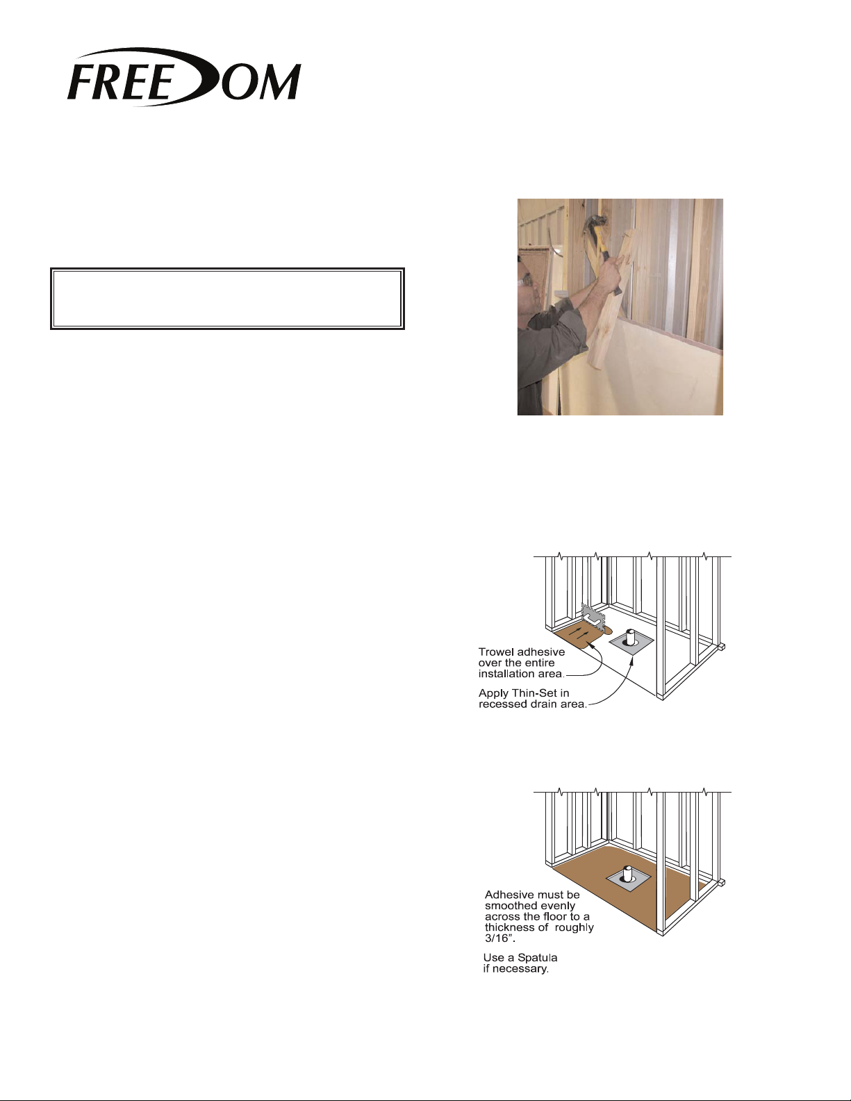
Using a 1/2” notched trowel, apply adhesive evenly over the
pan contact area. Bring the adhesive up to the threshold
pencil mark and also make sure the adhesive will be in
contact with the back side of the pan. The long edge of
the trowel may be needed to get the adhesive to the far
back of the contact area where the pan is resting against
the framing studs in a vertical position. (Pan not shown in
Figures 13 A and B).
After the adhesive is troweled over the sub oor, use a
spatula to wipe the adhesive over the entire area where
the pan will sit. The exception will be the drain box area.
This area will be lled with thin-set non shrink mortar. Do
not ll this area above the oor line and do not spill any of
this thin-set material onto the contact adhesive. See Figure
13B
Non shrink thin-set mortar can be purchased at any
local home improvement store. Please follow the mixing
directions on the bag.
Installation Instructions
Wood
Figure 15
In this step, apply the adhesive to the at oor area and ll
the boxed area around the drain pipe with the Thin-Set
mortar.
17. After the adhesive and thin-set materials are in place,
rotate the pan back into place for installation.
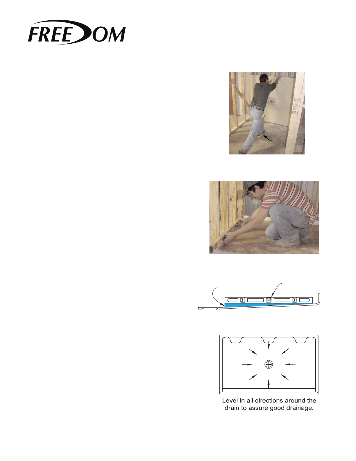
(Hint) In order to reach the pan without stepping on the
adhesive, place a short piece of wood over the drain area. Use
this to step on to remove the 2 x 4 that is holding the pan
against the back framing. See Figure 15
NOTE: The working life of the ooring adhesive is roughly
one hour. (Refer to the label on the adhesive for actual
working time). After step 16 is complete, the entire
installation process though step 23 must continue. If for
any reason the installation cannot be completed within the
working time of the adhesive, after step 16, jump ahead to
step 23.
Rotate the pan back to the horizontal position. As you
lower the pan to the sub oor, align the drain pipe with the
drain tting, and with the pencil mark at the front of the
threshold.
When the pan is seated into the adhesive, place the
cardboard on the shower oor for protection. Thoroughly
walk around in the shower. This will assist in seating the pan
into the adhesive.
Floor Level To
Drain - No Humps
Figure 16
Figure 17A
Figure 17B
2 Ft. Level
Page 8

Multi-Piece Sectional Product
Marketing Materials
Product Sheets
Pricing
www.freedomshowers.com
Attach the pan to the studs by installing the at top/pan
head screws through the holes drilled into the ange.
Snug the screws up tight so the screw heads will be clear
of the side wall panels for assembly. Use care not to
overtighten to the point that causes ange breakage.
18. Before installing the walls, conrm the ledges
where the walls sit are level. Check with a long
level as shown in Figure 16. If there is an out of level
condition, remove screws and adjust as required.
19. Before the adhesive cures, conrm the oor slope to
the drain has been maintained. To do this, use a 2 foot level
at various points around the drain to the adjacent wall to
check for draft. Make sure there is a downward slope to
the drain in all directions around the drain. Visually inspect
the oor to be sure there are no humps or dips that could
cause improper drainage.
See Figure 17A and 17B.
20. The next step will be to place the wall panels on the
pan. The back wall will be installed rst. If the water control
valve is in the back wall, carefully measure and mark the
location on the surface of the wall panel. If installing in a
shower with a two piece back wall, the valve probably will
be installed through the lower wall panel. Make certain the
valve does not conict with
the mounting ange or seam. Read the installation
instructions provided by the valve manufacturer. Before the
Trial t, carefully drill the valve hole (s) in the panel. When
drilled,dry Trial t the back wall panel (s) on the shower
pan to test the t.
Conrm the gap where the wall seats to the pan is 1/8” or
less. Make sure the seam for the two piece wall is also 1/8”
or less. Adjust the valve hole size and location if required.
Lift the wall panel with the valve hole away. Complete
the valve installation and connection to hot and cold
water supply at this time. Also complete shower supply
connection. Strap pipes to framing if required. This is the
last access to the plumbing before the wall is permanently
installed.
21. If all ts are good, proceed with the installation of the
the back wall. The installation procedures described in this
step apply for installation of one or two piece back walls.
Wipe clean the ledges on top of the pan. Apply a
Installation Instructions
continuous bead of 100% RTV silicone caulking along the
back ledge of the pan where the back wall will sit. The
bead should be placed at the middle of the ledge, and be
3/8” wide. The bead should go completely around each
alignment pin.
There are slots on the underside of the wall. There are
alignment pins in the pan that will insert into the slots on
the bottom of the wall. See the detail in Figure 19.
The lower section of the back wall is the panel with a
single, molded soap dish. Lift this panel up and carefully
lower it onto the back ledge on the pan.
Push the wall panel down to seat it in the caulking.
Check the t for level and plumb.
Note to installer: There is a difference having the bubble
between the lines and a plumb wall. The wall must be
VERY plumb or a gap larger than 1/8” will be present
where the side walls mate the back wall. Use wood shims
or furring strips to ll any space between the back wall
ange and the studs.
Align the wall section where it meets the shower pan
so it is centered on the pan, and install wood shims or
furring strips if necessary.
Pre-drill the mounting anges. Attach the wall with screws
through the back wall ange into the framing. Be sure the
wall panel remain level and plumb. (For the 4836 4 piece,
this step will apply for the entire back wall as one piece).
22. For ve piece units, the next step is to place the top
section of the back wall. Clean the back ledge and apply
a continuous bead of 100% RTV silicone caulking along
the ledge of the back wall where the top part of the wall
will sit. The bead should be 3/8 wide and placed at the
middle of the ledge. It should go completely around each
alignment pin.
Lift the top back wall panel and set it on top of the lower
wall. Press the panel down to seat in the caulking. The
top and bottom wall panels must be level and plumb.
Shim if necessary. The seam between the panels should
be no more than 1/8”. Pre-drill holes and attach with
screws along the top back ange into the framing studs.
Make sure the two wall panels are in alignment and are
level and plumb. Place level or straight edge on both
vertical ange where the wall will mate to the back wall
and check to assure there are no gaps. (For the 4836
Page 9

Multi-Piece Sectional Product
Marketing Materials
Product Sheets
Pricing
www.freedomshowers.com
four piece which has a single piece back wall panel, skip this
step).
23. Side wall installation. The side wall panels are slotted on
the bottom. The alignment pins in the pan will index with
these slots. The slots will allow the side wall panel to slide
about one inch to meet the back wall panel.
If the water control valve is located on one of the side
walls, it is important to dry trial t that panel rst. Carefully
measure and mark the location of the valve on the surface
of the side wall. Read the installation instructions provided
by the valve manufacturer. Carefully drill the valve hole(s).
Trial t the side wall panel to the shower pan. Wipe clean
the side ledge. This next step is a two person job.
Lift the side wall panel and set it on the ledge. Set the panel
so it is within one inch of the vertical back wall seam. Make
sure the pins in the pan index with the slots on the bottom
of the wall. Clear your ngers and slide the wall panel
toward the back wall. Make sure the alignment pins in the
back wall index into the holes on the side wall.
When seated, the seam should have a minimal gap of
1/8” or less. If not, push the end of the side panel until the
vertical seam closes. When in place, check the t of the
valve hole. Adjust size and location if required.
When the t is good, lift the wall panel away. Complete
the valve installation and connection to hot and cold
water supply at this time. Also complete shower supply
connection. Strap pipes to framing if required. This is the last
access to the plumbing before the wall is permanently
installed.
Clean the side ledge and apply a continuous 3/8” bead of
100% RTV silicone caulking along the entire length of the
mating ledge of the shower pan. Apply the caulk completely
around each alignment pin.
Clean and apply a continuous 3/8” bead of 100% RTV
silicone caulk along the entire length of the vertical
surface of the back wall where the side wall panel mates
to the back wall. Apply the caulk completely around each
alignment pin.
Lift the side wall and place it on the pan. Make sure
alignment pins on the pan and back wall line up. Clear
ngers and slide the wall into the installed position.
Installation Instructions
Conrm t and level. Inspect that the grout lines on the
side wall match up with the grout lines on the back wall.
Using a grease pencil or china marker to make a short line
across the grout lines makes it easier to see if the grout
lines are in alignment.
Pre-drill mounting anges and attach to framing studs with
screws. Make sure wall panel remains level and plumb and
the seam is tight.
Repeat the procedures in Step 22 for opposite side wall.
24. Now that all wall panels are installed, remove the
protective cardboard from the oor and use a 2 foot level
to re-check the downward oor draft to the drain. Use the
same procedure as described in Step 18 of this manual.
25. Install the rubber caulking gasket around the drain pipe.
Trim the length of the pipe if necessary. Apply soap to the
caulking gasket to lubricate it. Place the caulking gasket on
the drain pipe and press it down into the drain assembly
until it seats. Snap the strainer plate onto the drain.
Pour water across the oor to conrm good draft to the
drain so the water drains completely with no puddling.
Make certain the drain does not leak.
Note: The manufacturer and supplier of this product is not
responsible for leaking drain conditions. Proper installation
of the drain tting and pipe is the installers responsibility.
Since there is minimal oor slope to the drain, it is
critical factory slope be maintained so the shower drains
well. To accomplish this, temporary bracing must be put in
place to assure the oor remains in the proper position as
the adhesive cures.
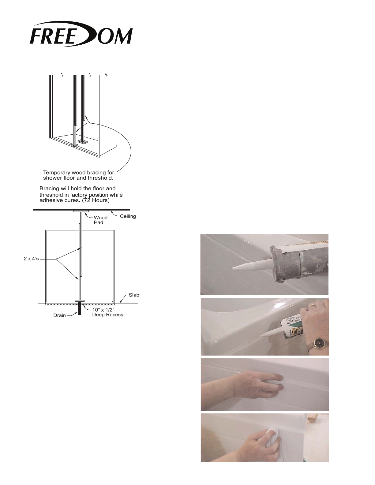
Before installing the bracing, place a padded piece of wood
on the top center of the threshold and directly on top of
the drain. Pad the wood with soft cloth or cardboard to
prevent damage to the nish.
Install temporary 2 x 4 stud bracing so they sit on top of
these wood pieces. Attach these studs to the room framing
above the shower, or pad to the ceiling. See Figure 26
26. Remove the temporary bracing after 72 hours. Place a
piece of cardboard in the shower to protect the nish.
Caulk all seams with white acrylic bathtub caulk.
Page 10
Multi-Piece Sectional Product
Marketing Materials
Product Sheets
Pricing
www.freedomshowers.com
Installation Instructions
SEAM CAULKING INSTRUCTIONS
Materials and tools required:
• acrylic latex caulk
• wiping cloths/rags
• clean water
• caulking gun
• cup
1. Cut off tip of caulk tube diagonally with opening
no larger than 1/8”. Figure 27
2. Run a continuous bead of caulk at the seam between
the two parts. Figure 28
3. Smooth caulk gently with a wet ngertip. Figure 29
4. Using a clean rag, wipe off excess water and caulk.
Figure 30
Figure 27
Figure 26
Figure 28
Figure 29
Figure 30
Page 11

Multi-Piece Sectional Product
Marketing Materials
Product Sheets
Pricing
www.freedomshowers.com
INSTALLATION INSTRUCTIONS FOR SHOWER
SEATS WITH SWING DOWN LEGS
(This style seat has four (4) adjustable height legs)
Your seat with swing down legs is fully assembled.
Remove it from the box and proceed as follows:
1. Choose the height of the seat you want. Barrier Free
style showers will typically have fold up seat installed at
17” to 19” height.
2. After selecting the height you desire, adjust each of the
four legs to that height while maintaining the seat in a
level position. Lock each of the lock nuts.
3. Place the seat against the wall of the shower where
you want the seat to be located. Seat may be centered
on the wall for a Barrier Free installation.
4. With the seat placed against the mounting wall,
position the two hinges to the wall. Using a pencil, mark
the three holes (3) holes in the ange onto the wall for
each hinge. Remove seat from wall.
5. Using a power drill with a 0.120” diameter drill through
the wall the three (3) mounting holes for each ange.
6. Apply silicone caulking around and inside each drilled
hole before installing the seat.
7. Place the seat against the mounting wall with each
hinge aligned to the mounting holes. Utilizing the six (6)
#10 x 2” Stainless Steel screws, place a Phillips screw
driver into your power drill and securely tighten each of
the six (6) screws.
THIS COMPLETES THE INSTALLATION OF THE SEAT
INSTALLATION INSTRUCTIONS FOR GRAB
BARS
Recommended tools for installation:
1/4” Power Drill
1/8” drill bit when drilling through berglass
#2 Phillips Screw Driver and/or Phillips drill insert
1/2” Open end wrench or a small Crescent wrench
Tape measure
Pencil/pen
Center Punch
Silicone Caulk
Installation Instructions
1. As indicated earlier in this manual, wood reinforcements
must be solidly installed behind the tile wall surface to provide
a secure mounting surface to attach the grab bars. Grab bars
must be installed at these locations only.
2. Select the particular size and style of grab bar you want to
install. Certain grab bars have snap in place ange covers, and
others have exposed anges.
3. For grab bars with snap in place ange covers, use the
handle of a Phillips screw driver to tap back the covers on
the bottom edge of the covers. It will be convenient in the
installation process if the covers are tapped together in the
center of the grab bar.
4. Determine the position you want the to install the bar.
Place the bar against the wall. Using a pencil, mark the location
of each mounting hole at both ends of the bar.
5. Using a power drill with a 1/4” diameter carbide tipped drill
bit, drill, each mounting hole.
6. Apply silicone caulking around and inside each drilled hole
before installing the grab bar.
7. Take two (2) of the #10 x 2” Stainless Steel screws. By
hand, start one mounting screw in each end of the bar into
the wall.
8. Use a power drill with a Phillips drill bit to fully install these
mounting screws.
9. Take the remaining #10 x 2” screws and place them into
the remaining open holes. Use care to snug up the screws,
but to not over-torque that the screws strip out the factory
installed backer board.
10. If installing a bar with snap-on covers, move the covers
into place at each ange. Twist the covers clockwise or
counter clockwise to tighten the covers onto the anges.
THIS COMPLETES THE INSTALLATION OF THE GRAB BAR
Page 12

Multi-Piece Sectional Product
Marketing Materials
Product Sheets
Pricing
www.freedomshowers.com
INSTALLATION INSTRUCTIONS FOR
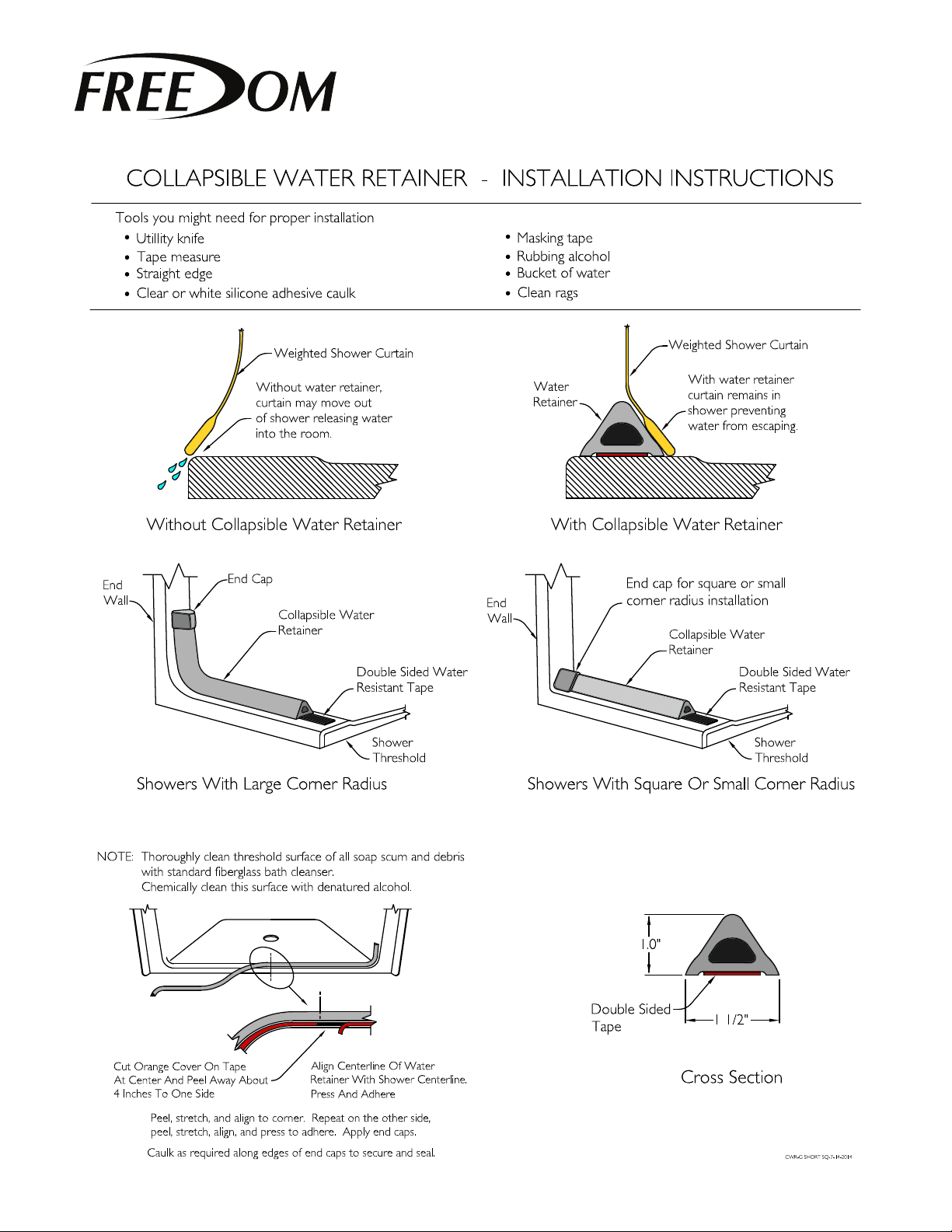
COLLAPSIBLE WATER RETAINERS
Important considerations before you begin: Most
manufactured units are designed with a radius where
the oor transitions or meets the wall. This is to
ensure proper structural strength where the wall
meets the oor. The installation of end caps is highly
recommended on radius models for proper t and
nish. The caps will also help to keep your curtain inside
the water barrier. A properly sized curtain with heavy
tape weights combined with a water retainer is the
most complete and effective system available today.
Installation of radius models: (For Finished End Cap
Installation) Make sure you have ordered the correct
length. See chart below. The water retainer strip is
designed to travel along the oor to the wall radius
until vertical, then capped. (Less Cap Installation) Cut
the retainer strip to the shape of the radius where
the wall and the oor meet, then caulk. Caps are not
required in applications where a 90-degree corner is
standard.
Size Verication Chart for all Factory Manufactured
Shower Units
For most Acrylic Showers:
• 36” ADA barrier free (36”I.D. opening)
42CWR-White
• 48” barrier free (45-46” I.D opening)
52CWR-White
• 60” ADA barrier free shower (60” I.D. opening)
66CWR-White
• Finished End Cap
CWRCAP-White
Note: 1 ½” wide at mounting surface required.
Identifying proper mounting location: It will be helpful to
determine whether your Gel-coat or Acrylic reinforced
shower unit model has a small molded ridge or “water
runoff assist” or trench design on your unit. You will
nd this feature on the oor of approximately 1-3
Installation Instructions
inches from the front entry edge of your shower unit.
The inside edge of the water retainer should rest on
the crown of the ridge allowing the water to run off
properly. Use this ridge as your guide to mounting the
retainer parallel with the water run off ridge.
Models less the ridge: All name brand barrier free
showers that may not have a water run off ridge or
recessed trench and applications such as tile, marble
or cement oor surfaces, purchaser must determine
the proper mounting location and length. Helpful hint:
determine by desired location of curtain or directly
below curtain rod.
Tools & Materials required: Utility Knife, Tape measure,
Straight edge, Clear or White 100% Silicone Adhesive
caulk, Blue Masking tape, Rubbing Alcohol, bucket of
water and clean rags.
INSTALLATION STEPS WITH FINISHED END CAPS
1. Thoroughly clean threshold surface of all soap scum
and debris using standard bath cleanser. Chemically
clean surface with rubbing alcohol.
2. Verify the required length anticipating the vertical rise,
making certain there is enough retainer strip to make a
vertical rise on the end walls.
3. Determine and mark center point of shower.
4. Determine and mark center point of water retainer
strip.
5. Turn over water retainer strip and make cut on
orange peel off strip at half way mark. Peel off a
portion (approx. 4”) of the orange peel off strip in one
direction exposing the adhesive.
6. Align strip with pre-determined pencil mark or
molded ridge crown of shower unit starting at the half
way mark. Press on and adhere approximately 4” of
strip. Pull and stretch to wall and align before removing
remainder of orange peel off strip. Press into place.
7. Peel, stretch, alien and pull remaining half to wall.
Press into place.
Page 13

Multi-Piece Sectional Product
Marketing Materials
Product Sheets
Pricing
www.freedomshowers.com
8. Push in the male end of your end cap into the water
retainer. Adhere end cap to unit with adhesive caulk
and wipe clean. White or clear adhesive type caulk is
recommended.
9. Use masking tape to temporarily hold cap in place
until adhesive cures.
10. Optional: The outer edges beneath the retainer
may be caulked if desired to prevent soap and shower
debris from lodging beneath the retainer. The adhesive
tape does not extend to the edge (by design) to allow
the retainer to absorb the impact energy of a rolling
shower chair in high use applications. Wipe off excess
caulk and let cure (according to caulk specications)
prior to shower use.
STEPS LESS FINISHED END CAPS
Installation Instructions
11. Caulk end cuts and wipe clean. A silicone adhesive
caulk is recommended.
12. Optional: The outer edges beneath the retainer
may be caulked if desired to prevent soap and shower
debris from lodging beneath the retainer. The adhesive
tape does not extend to the edge by design to allow
the retainer to absorb the impact energy of a rolling
shower chair in high use applications. Wipe off excess
caulk and let cure (according to caulk specications)
prior to shower use.
1. Thoroughly clean threshold surface of all soap scum
and debris using standard bath cleanser. Chemically
clean surface with rubbing alcohol or equal.
2. Verify the required length anticipating the radius
shaping required on each end of the strip.
3. Determine the shape of the end cut required for
proper t and nishing.
4. Begin at one end only.
5. Create template of wall shape (if necessary) with
cardboard or material of choice.
6. Trace shape onto retainer, cut and trim with utility
knife.
7. Beginning on the shaped end, peel back a small 4”
section of the orange peel off strip.
8. Align strip with pre-determined pencil mark or
molded ridge crown of unit. Press on and adhere the
4” section of exposed strip into place.
9. Before removing remainder of orange peel off strip,
stretch retainer to opposite wall, mark and template for
proper location proceeding nal cut.
10. Remove remaining orange peel off strip and stretch
retainer to its nal position. Press and adhere into
place.
Page 14
Multi-Piece Sectional Product
Marketing Materials
Product Sheets
Pricing
www.freedomshowers.com
Installation Instructions
Page 15
Multi-Piece Sectional Product
Marketing Materials
Product Sheets
Pricing
www.freedomshowers.com
Installation Instructions
Copyright 2015 FRE/0515/6MAN109FRDM
Page 16
Marketing Materials
Product Sheets
Pricing
www.freedomshowers.com
Installation Using Epoxy Adhesive
1. Ensure the stud pocket is the correct dimension,
including the location of the drain hole and recessed
cut out.
2. Ensure the fl oor is level and free of any debris, including
dust and dirt (will impair adhesion).
3. Install the drain fi tting and prepare the drain pipe.
4. Place the pan/shower into the pocket and check for
proper level and alignment. Adjust accordingly.
5. Dry fi t all walls as stated in the standard installation
instruction (for sectional models only).
6. Mark the location and prepare the pan/shower as stated
in the standard installation instructions.
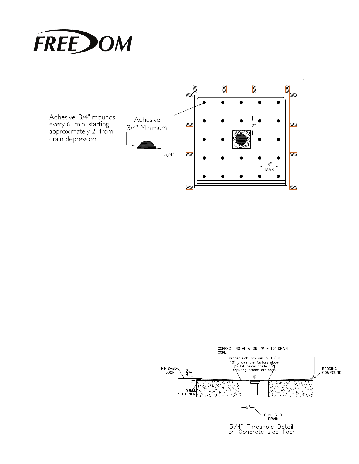
7. Tilt pan out of the way or remove the shower and apply
adhesive in the following manner:
a. Apply adhesive in small mounds ¾” in height.
b. Mounds must be NO MORE than 6” apart and
applied in a grid-like manner.
c. Place adhesive over entire pocket surface,
beginning at the back and working toward the
front.
d. Ensure material is applied near the drain cutout/
box out.
8. Place pan/shower back into position and ensure it is level.
9. Apply a small amount of adhesive between two pieces
of scrap material. This will be checked later to verify
set time.
10. Secure the unit as stated in the standard installation
instructions.
11. Allow 2 hours minimum for the adhesive to set.
Verify by checking the scrap pieces from step 9.
12. Continue the installation as stated in the standard
installation instructions.
Copyright 2015 FREEPOXY/0715
 Loading...