

Freedom9 Slim 100, Slim 300, FSL100, FSL300M User Manual

freeGuard Slim Appliances
User Guide
Part No.: FSL100, FSL300M
Vers ion: V4R2

Copyright Notice
© Copyright 2007 Freedom9 Inc.
All Rights Reserved.
Under the copyright law, this manual and the software described within cannot be copied in
whole or part, without written permission of the manufacturer, except in the normal use of the
software to make a backup copy. The same proprietary and copyright notices must be affixed to
any permitted copies as were affixed to the original. An exception does not allow copies to be
made for others, whether or not sold, but all of the materials purchased can be sold, given, or
loaned to another person. Under the law, copying includes translating this information into
another language or format.
Information contained in this document is subject to change without notice.
Trademarks
Hyper- Terminal is a registered trademark of Hillgraeve Inc. SecureCRT is a registered trademark
of VanDyke Technologies Inc. Other products mentioned in this document may be trademarks
and/or registered trademarks of their respective companies and are the sole properties of their
respective company.

Contents
Ch. 1: Getting Started ...................................................................................................... 1-1
Document Conventions.............................................................................................. 1-2
Document and Command Line Interface (CLI) Conventions ................................ 1-2
Browser-Based Graphical User Interface (WebGUI) Conventions ....................... 1-2
Illustration Conventions......................................................................................... 1-3
Introduction to the Appliances.................................................................................. 1-4
Product Description............................................................................................... 1-4
Supported Features ............................................ .... ... ... .................................... .... 1-5
Accompanying Documentation on Software CD................................................... 1-5
Startup Configuration for SlimLine 100................................................................. 1-6
Startup Configuration for Slim 300M .................................................................... 1-6
Default Behavior.................................................................................................... 1-6
Before You Install the Freedom9 Appliance ............................................................ 1-6
Installation Precautions for SlimLine 100.............................................................. 1-6
What You Must Know Before You Install the Appliance................................ ....... . 1-7
Installing the Appliance...................................... .................................... ... ................. 1-7
Connecting the Power............................. ................................... ... ........................ 1-7
Connecting the Appliance to Other Network Devices................................ ... .... ... . 1-7
Configuring the Appliance ......................................................................................... 1-7
Connecting the Console Cable ........... .... ... ... ... ... .... ... ... ... .... ... ... ... .... ... ...... ... .... ... . 1-7
Slim 100 Appliance Specifications ........................................................................... 1-8
Slim 100 Appliance..................................... ................................... ........................ 1-8
LED Activity for Slim 100....................................................................................... 1-9
Console Interface for Slim 100.............................................................................. 1-9
Slim 300 Appliance Specifications.......................................................................... 1-10
Slim 300 Appliance.............................................................................................. 1-10
LED Activity for
Slim 300 Console Interface.................................................................................. 1-11
Configuring the Software for
Default Configuration .......................................................................................... 1-11
Configuring the Default Route for Management Traffic....................................... 1-12
Viewing the Policy Configuration......................................................................... 1-12
Configuring a Policy............................................................................................ 1-13
Ch. 2
:Freedom9 Network Appliances System Management .. ....................................... 2-1
Using the Console to Manage the
Viewing Console Interface Settings ...................................................................... 2-2
Setting the Console Display....... ... ... ... .... ... ... ... ... .... ... ... ... .... ... ... ....... ... ... ... ... .... ... . 2-2
Setting the Console Timeout .. .... ... ... ... .................................... .............................. 2-2
Exiting the Console............................................................................................... 2-2
Using SSH to Manage the
Enabling SSH on a Specific Interface ................................................................... 2-3
Disabling SSH on a Specific Interface .................................................................. 2-3
Slim 300..................................................................................... 1-10
Freedom9 Network Appliances .............................. 1-11
Freedom9 Network Appliance .............. ... .... ... . 2-2
Freedom9 Network Appliance....................................... 2-3
. . . . .
FSL100 User Guide iii

Viewing SSH Settings........................................................................................... 2-3
Generating New SSH Host Keys .......................................................................... 2-3
Managing Users for the Freedom9 Network Appliance ........................................... 2-4
Changing Your Administrator Password................. ... ... ... .... ... ... ........................... 2-4
About Additional Types of Users........................................................................... 2-4
Changing the Admin-r Password .......................................................................... 2-4
Managing Software for the Freedom9 Network Appliance...................................... 2-6
Storing Software Image Files in Flash Memory .................................................... 2-6
Downloading New Software.................................................................................. 2-6
Uploading New Software....................................................................................... 2-6
Saving MOS Software to Flash Memory Using TFTP... ... .... ................................. 2-7
Saving Boot Software to Flash Memory Using TFTP.............. ... ... .... ... ................. 2-7
Setting the Software as Primary or Secondary Image.......................................... 2-7
Upgrading the Software Using the Web User Interface.......................... .............. 2 -7
Saving the Configuration File for Export ............................................................... 2-8
Executing the Configuration File From the TFTP Server...................................... 2-8
Executing a Saved Configuration File. .... ... ...... ... .... ... ... ... .... ... ... ... .... ... ... ... ... .... ... . 2-8
View the Running Configuration............................................................................ 2-8
View the Saved Configuration............................................................................... 2-8
Resetting and Restarting the Freedom9 Network Appliance ....... ... ....... ... ... ... .... .. 2-10
Resetting the Freedom9 Network Appliance................... ... .... ... ... ....................... 2-10
Resetting the Software To Use the Original Filename........................................ 2-10
Restarting the Freedom9 Network Appliance ..................................................... 2-10
Additional System Management Tasks .................................................................. 2-11
Viewing System Information................................................................................ 2-11
Configuring Domain Names................................................................................ 2-11
Deleting Domain Names..................................................................................... 2-12
Configuring Host Names..................................................................................... 2-12
Deleting Host Names.......................................................................................... 2-12
Using Network Time Protocol (NTP) ........... ............................................................ 2-13
Configuring NTP Settings.................................................................................... 2-13
Configuring the NTP Update Interval.................................................................. 2-13
Viewing Current NTP Settings ............................................................................ 2-14
Deleting NTP Server IP Entries........................................................................... 2-14
Configuring Manual Update Using NTP.............................................................. 2-14
Maintaining Clock Settings with NTP......... ......................................................... 2-14
Configuring the Clock to Use NTP...................................................................... 2-15
Configuring the Time Zone.................................................................................. 2-15
Using Domain Name Service (DNS) ........................................................................ 2-16
Deleting DNS Host IP Addresses........................................................................ 2-16
Displaying Current DNS Host Settings................................................................ 2-17
Using Ping ................................................................................................................. 2-17
FSL100 User Guide iv

Using Traceroute ...................................................................................................... 2-17
Ch. 3: Managing Traffic Flow .......................................................................................... 3-1
Shaping Traffic Flow....... .................................... ... .................................... ................. 3-1
Overview............................................................................................................... 3-1
Network Layout..................................................................................................... 3-2
Scenario Description............................................................................................. 3-2
Analyzing and Shaping Traffic .............................................................................. 3-6
Ch. 4: Configuring Attack Prevention ............................................................................ 4-1
What is Freedom9 Network AntiDoS? ............. . ... ... .... ... ... ... .... ... ...... .... ... ... ... ... .... ... . 4-1
Flooding Attacks.................................................................................................... 4-1
Port Attacks............................ .... ... ... ... .... ................................... ........................... 4-1
Attacks Through Malformed Packets.................................................................... 4-1
Valid But Potentially Dangerous Packets................................ ... ... .... ... ... ...... .... ... . 4-2
Enabling DDoS Prevention ........................................................................................ 4-2
Flooding Attacks.................................................................................................... 4-2
Port Attacks............................ .... ... ... ... .... ................................... ........................... 4-2
Attacks Through Malformed Packets.................................................................... 4-2
Attacks Through Valid But Potentially Dangerous Packets........ ....... ... ... ... ... .... ... . 4-2
Enabling DDoS Logging........................................................................................ 4-3
Attack Overview Table........................................... .................................... ... .............. 4 -3
Logging Command Index...................................................................................... 4-6
Ch. 5: Traffic Flow Reporting.......................................................................................... 5-1
Top-Talkers.................................................................................................................. 5-1
Logging Overview....................................................................................................... 5-1
Logging........................................................................................................................ 5-1
Logging Levels...................................................................................................... 5-1
Log Modules.......................................................................................................... 5-2
Traffic and Event Log Management...................................................................... 5-3
Log Module Settings.............. ................................... .... ................................... ........... 5-3
Setting Log Modules ........................................... .... ................................... ........... 5-3
Disabling Log Module Settings.............................................................................. 5-3
Viewing the Log Module Settings.......................................................................... 5-3
Viewing the Traffic and Event Log ........................................................................ 5-4
Admin Mail Server........ ... .... ................................... .................................... ... .............. 5 -5
Configuring Freedom9 Network Appliances to Send E-mail Notifications ............ 5-5
Deleting the Admin Mail Server............................................................................. 5-5
Removing E-mail Addresses from the Admin Mail Server.................................... 5-6
Syslog Management .............. ................................... .... ................................... ........... 5-6
Deleting the Syslog Host IP Address.................................................................... 5-7
Disabling the Syslog Host Log Options................................................................. 5-7
Syslog Message Format ....................................................................................... 5-7
Reviewing Message Logs .......................................................................................... 5-8
Conventions.......................................................................................................... 5-8
Acronyms.............................................................................................................. 5-9
Anatomy of a message .... ... ... .... ... ... ....... ............................................................ 5-11
Traffic Logging .................................................................................................... 5-12
Traffic Logging Messages................................................................................... 5-13
. . . . .
FSL100 User Guide v

DOS .................................................................................................................... 5-13
POLICY............................................................................................................... 5-14
SESSION............................................................................................................ 5-14
Reviewing Event Logs.............................................................................................. 5-15
Address............................................................................................................... 5-16
Notification .......................................................................................................... 5-16
System................................................................................................................ 5-17
ARP..................................................................................................................... 5-17
Interface.............................................................................................................. 5-18
Policies................................................................................................................ 5-19
PPP..................................................................................................................... 5-20
Route................................................................................................................... 5-23
Schedule............................................................................................................. 5-24
Service................................................................................................................ 5-24
SNMP.................................................................................................................. 5-25
Zone.................................................................................................................... 5-25
Ch. 6: Advanced Policy Configuration........................................................................... 6-1
About Security Policies.............................................................................................. 6-1
About Traffic Flow Among Policies ....................................................................... 6-1
About Security Policy Types ................................................................................. 6-2
Configuring Interzone Policies .............................................................................. 6-2
Configuring Global Policies................................................................................... 6-3
Configuring Policies................................................................................................... 6-3
Creating Policies.................................................................. ................................. 6-3
Naming Policies .................................................................................................... 6-5
Reordering Policies............................................................................................... 6-5
Disabling Policies.................................................................................................. 6-6
Re-enabling Policies ............................................................................................. 6-6
Deleting Policies.................................................................................................... 6-6
Viewing Policies.................................................................................................... 6-6
Enable Policy Logging............................................................. .............................. 6-8
Using the Set Alert Command............................................................................... 6-8
Configuring Address Objects.................................................................................... 6-9
Creating Address Objects................................ ... .... ................................... ........... 6-9
Deleting Address Objects.................................................................................... 6-10
Modifying Address Objects ................................................................................. 6-11
Creating Address Groups........................................................... ......................... 6-11
Adding Objects to an Address Group.................................................................. 6-11
Deleting Address Groups.................................................................................... 6-13
Deleting Address Objects from an Address Group ............................................. 6-13
Adding Comments to Address Groups................................................................ 6-13
Configuring Service Objects.................................................................................... 6-14
FSL100 User Guide vi

Viewing Predefined Service Objects................................................................... 6-14
Configuring Custom Service Objects.................................................................. 6-14
Deleting Service Objects..................................................................................... 6-15
Modifying Service Objects................................................................................... 6-15
Configuring Service Timeouts............................................................................. 6-15
Configuring Service Groups.................................................................................... 6-16
Creating Service Groups............................................................... ...................... 6-16
Deleting Service Groups..................................................................................... 6-17
Removing Service Objects from Groups............................................................. 6-17
Modifying Service Groups................................................................................... 6-17
Adding Comments to Service Groups................................................................. 6-18
About Schedules....................................................................................................... 6-18
Creating One-time Schedules.... ... ... ... .... ............................................................ 6-18
Creating Recurring Schedules...... ... ... .... ............................................................ 6-19
Adding Schedules to Policies..... ... ... ... .... ............................................................ 6-20
Deleting Schedules............................................................................................. 6-21
Viewing Schedules.............................................................................................. 6-22
Ch. 7: Monitoring Traffic.................................................................................................. 7-1
Monitoring Traffic Using Threshold Alerts............................................................... 7-1
Overview............................................................................................................... 7-1
Network Layout..................................................................................................... 7-1
Scenario Description............................................................................................. 7-2
Initializing the Freedom9 Network Appliance........................................................ 7-3
Setting Up Alerts.... ... .... ... ... ... .... ................................... .................................... ... . 7-3
Setting Up the Logging Infrastructure ................................................................... 7-4
Setting Up Policies. ... .... ... ... ... .... ................................... .................................... ... . 7-4
Analyzing Traffic and Sending Alerts ....................................................................... 7-6
Using the Set Alert Frequency Advanced Option.................................................. 7-6
Traffic Analysis Using NetFlow ................................................................................. 7-6
Overview............................................................................................................... 7-6
Network Layout..................................................................................................... 7-7
Initializing the Freedom9 Network Appliance........................................................ 7-8
Setting Up the NetFlow Infrastructure................................................................... 7-8
Setting Up Policies. ... .... ... ... ... .... ................................... .................................... ... . 7-9
Performing Traffic Analysis Using NetFlow........................................................... 7-9
Managing Peer-to-Peer Traffic................................................................................. 7-10
Network Layout................................................................................................... 7-10
Initializing the Freedom9 Network Appliance...................................................... 7-10
Setting Up the Logging Infrastructure ................................................................. 7-11
Setting Up Deep Packet Inspection (DPI) Profile................................................ 7-11
Setting up Policies............................................................................................... 7-13
Identifying and Handling Peer-to-Peer Traffic..................................................... 7-13
Alert Configuration ................................................................................................... 7-14
Policy Alerting ..................................................................................................... 7-14
Connection Rate ....... .... ... ................................... .................................... ... ......... 7-14
Aggregate Bandwidth.......................................................................................... 7-14
Connection Bandwidth..... ................................... .... ................................... ......... 7-14
. . . . .
FSL100 User Guide vii

Policy Configurator.............................................................................................. 7-15
Ch. 8: Using SNMP........................................................................................................... 8-1
SNMP MIB Groups ....... ... .... ... ... ... .................................... ................................... ........ 8-1
SNMP System Object ID (OID)............................................................................. 8-1
System Group.................................. .................................... ... .............................. 8-1
Interface Group..................................................................................................... 8-2
Address Translation Group................................................................................... 8-2
IP Group................................. .................................... ... .................................... .... 8-2
IP Address........................... ... .... ... ... ... .................................... .............................. 8-3
IP Route.... .................................... ... .................................... ................................. 8-3
IP Net to Media ..................................................................................................... 8-3
ICMP Group Scalars..... ... ... ... .... ... ... .................................... ................................. 8-4
SNMP Group......................................................................................................... 8-4
Transmission Group (DOT3STATs)...................................................................... 8-5
Transmission Group (DOT3COLLISION).............................................................. 8-5
Configuring SNMP on the Freedom9 Network Appliance..................................... 8-5
Enabling SNMP on a Specified Interface.................................................................. 8-6
Configuring the SNMP Community String............................................................. 8-7
Configuring the SNMP Listener Port..................................................................... 8-7
Configuring the SNMP System Name................................................................... 8-7
Deleting the SNMP System Name........................................................................ 8-7
Configuring the SNMP System Locations............................................................. 8-7
Deleting the SNMP location.................................................................................. 8-7
Configuring the SNMP System Contact................................................................ 8-7
Deleting the SNMP System Contact..................................................................... 8-7
Viewing the SNMP Settings.................................................................................. 8-8
View the SNMP Community Settings.................................................................... 8-8
View the SNMP Statistics...................................................................................... 8-8
Viewing the Interface Statistics............................................................................. 8-9
Ch. 9: Security Zones and Interfaces................... ... ... ... .... ... ... ... .... ... ...... .... ... ... ... ... .... ... 9-1
Security Zones .................... ... ... .................................... ................................... ... ........ 9-1
Creating and Modifying Custom Security Zones..................................................... 9-3
Creating Custom Security Zones.......................................................................... 9-3
Deleting Custom Security Zones........................................................................... 9-3
Viewing Zone Configurations................................................................................ 9-4
Configuring Interfaces and Subinterfaces ............................................................... 9-5
Configuring Interfaces........................................................................................... 9-5
Binding Interfaces to a Security Zone..... ... ... ... ... .... ... ... ... .... ... ... ... ....... ... ... ... .... ... . 9-5
Moving Interfaces between Security Zones.......................................................... 9-6
Configuring Subinterfaces..................................................................................... 9-6
Deleting Subinterfaces.......................................................................................... 9-7
Configuring Interface Modes ..................................................................................... 9-7
FSL100 User Guide viii

Configuring NAT-Enabled Mode........................................................................... 9-8
Configuring Route Mode....................................................................................... 9-8
Viewing Interface Information................................................................................ 9-9
Configuring Transparent Mode ............................................................................... 9-10
Transparent Mode Overview.................................................................................... 9-10
Transparent Mode Simple Deployment............................................................... 9-11
Transparent Mode Management......................................................................... 9-11
Transparent Mode VLAN Filtering....................................................................... 9-12
Transparent Mode Simple ACL Functions.......................................................... 9-14
Advanced Interface Settings.................................................................................... 9-16
Configuring Maximum Transmission Unit (MTU) Settings .................................. 9-16
Configuring Interface Link Up/Down ................................................................... 9-16
Enabling Interface Management......................................................................... 9-18
Disabling Interface Management ........................................................................ 9-18
Setting the Interface Speed........................................ ... ... .... ... ... ... .... ... ... ...... .... .. 9-18
Ch. 10: Routing.......... ... ... ... ... .... ... ................................... .................................... ... ........ 10-1
Static Routes............................................................................................................. 10-1
Adding Static Routes........................... .... ... ... ... ... .... ................................... ......... 10-1
Deleting Static Routes......................................................................................... 10-2
Modifying Static Routes ...................................................................................... 10-2
Setting the Default Route......................................................................................... 10-2
Displaying Route Information.................................................................................. 10-3
Appendix A: Pre-defined Services ..................................................................................A-1
Appendix B: Glossary.......................................................................................................B-1
Appendix C: Alphabetic Listing of Log Messages.........................................................C-1
Appendix D: Notification and Safety Statements...........................................................D-1
. . . . .
FSL100 User Guide ix

FSL100 User Guide x

GETTING STARTED
. . . . .
Getting Started
This chapter describes how to install, configure, and manage the freeGuard Slim 100 appliance.
This chapter includes the following topics:
• Document Conventions on page 1-2
• Introduction to FSL100 Appliances on page 1-4
• Before You Install the FSL100 Appliance on page 1-6
• Installing the FSL100 Appliance on page 1-7
See also the Quick Start Guide which is provided with your FreeGuard Slim 100 appliance.
1
User Guide 1-1

1
GETTING STARTED
Document Conventions
This section explains the Command Line Interface (CLI), the browser based graphical user
interface (WebGUI), and the illustration conventions used in th is g ui de.
Some general documentation conventions include:
Document and Command Line Interface (CLI) Conventions
The following conventions are used when presenting the syntax of the command line interfac e
(CLI):
• References to MOS refer to the
Freedom9 firmware
• Values inside square brackets [ ] are optional.
• Values inside braces { } are required.
• For commands that require a selection from a pre-defined list of values, each value in the
list is separated by a pipe ( | ).
• Variables appear in italic.
• When a CLI command appears within the context of a sentence in this document, it is in
bold (except for variables, which are always in italic). For example: “Use the get system
command to display general information about the
Freedom9 Network appliance.”
Variable CLI values are described in Table 1-1.
Table 1-1 Variable CLI Values Used in This Guide
Variable CLI Value Description
addr_str Defines an IP address range assignment
dst_adr Destination address assigned in a policy
fqdn Fully Qualified Domain Name
ip_addr Defines an IP address assignment
number Numeric value assigned for a specific command
name_str Name value assignment
password_str New password assignment is required
src_adr Source address assigned in a policy
srvc Service assigned in a policy
zone name Zone used in a specific command
Browser-Based Graphical User Interface (WebGUI) Conventions
• Values inside square brackets [ ] are optional.
• Values inside braces { } are required.
• For commands that require a selection from a pre-defined list of values, each value in the
list is separated by a pipe ( | ).
• Variables appear in italic.
1-2 User Guide

GETTING STARTED
When a WebGUI command appears within the context of a sentence in this document, it is in bold
(except for variables, which are alwa ys in italic). For example: “Us e click on the XXXX command
to display general information about the Freedom9 Network appliance.”
Figure 1-1 shows the graphics used in illustra tions in this guide.
Illustration Conventions
Figure 1-1 Illustration Conventions.
Freedom9 Appliance
. . . . .
User Guide 1-3

1
GETTING STARTED
Introduction to Freedom9 Network Appliances
Product Description
FreeGuard Slim 100 appliances are compact in-line appliances that manage network traffic flows to
optimize and protect network and server infrastructures. Deployed in front of servers or network
equipment, the Freedom9 Network appliance is a non-intrusive solution for managing bandwidth
abuse or attacks against network infrastructure.
Based on
throughput while maintaining line quality and low latency . The appliances are configured using
granular user-defined policies identifying thresholds for session creat ion, per-flow bandwidth,
and aggregate bandwidth.
Applications for the appliances include:
RDX technology, the FSL100 appliances support monitoring network flows at 2Gbps
• In-line network flow monitor
• Deep inspection overlay
• Malicious traffic notification
• Bandwidth management
• Network health monitoring
1-4 User Guide

Supported Features
The following features listed in Table 1-2 through Table 1-5 are supported:
Table 1-2 Supported Features (Network Functions)
Network Functions Supported Features/Values
Static Routes 32
Dynamic ARP Entries 2K
Table 1-3 Supported Features (System)
System Supported Features/Values
Concurrent Sessions 192K
TCP Sessions per second (Route Mode) 15,500
Security Zones 254
VLANs 20
GETTING STARTED
. . . . .
VLANs in Transparent Mode 4095
Table 1-4 Supported Features (Policy)
Policy Supported Features/Values
Access Control Lists 500
Service Objects 512
Address objects per zone 500
Table 1-5 Supported Features (System Management)
System Management Logging,
Monitoring
Syslog up to 2 servers
SNMPv2 (trap) yes
SNMP Get yes
Command Line Interface yes
Supported Features/Values
Accompanying Documentation on Software CD
For information on configuring and deploying your Freedom9 Network appliance, refer to the
following documentation:
• Quick Start Guide
• User Guide
• CLI Reference Guide
User Guide 1-5

1
GETTING STARTED
Startup Configuration for Slim 100
Use the following default settings:
• Transparent Mode
• Bridge Interface IP Address: 192.168.1.1/24
• Eth0 Zone: Trust
• Eth1 Zone: Untrust
• Allow HTTP management
•
Freedom9 Networks appliance thresholds not configured
• Local logging not configured
• Default policy - Allow
Startup Configuration for Slim 300M
Use the following default settings:
• Transparent Mode
• Bridge Interface IP Address: 192.168.1.1/24
• Eth0 Zone: Trust
• Eth1 Zone: Untrust
• Eth 2 Management Zone: Trust
• Allow HTTP management
•
Freedom9 appliance thresholds not configured
• Local logging not configured
• Default policy - Allow
Default Behavior
• Allow any traffic
Before You Install the Freedom9 Appliance
Familiarize yourself with the following topics before installing the Freedom9 appliance:
• What You Must Know Before You Install the Freedom9 Appliance on page 1-7.
• Installing the
Installation Precautions for Slim 100
Freedom9 Appliance on page 1-7.
[WARNING] Obey these precautions when you install the Freedom9 appliance.
Observing these precautions can prevent injuries, equipment failures, and potential
shutdown of the Freedom9 appliance.
[WARNING] Always assume the power supply for the Freedom9 appliance is connected
to the power outlet.
1-6 User Guide

GETTING STARTED
<CAUTION> Room temperature might not be adequate for long term use of the Freedom9
appliance; for optimum environmental requirements for the appliance, refer to the FSL100
Appliance Specifications on page 1-8.
<CAUTION> Be careful of additional hazards, including frayed power cords, wet or moist floors, and
missing safety grounds.
What You Must Know Before You Install the Freedom9 Appliance
You must understand the following concepts before you install the Freedom9 appliance for
the first time:
• Basic understanding of TCP/IP.
• IP addresses and subnet masks.
Installing the Freedom9 Appliance
Connecting the Power
. . . . .
You must connect a power source to the appliance before you configure the ap pliance.
To connect the power:
1. On the appliance, plug the DC connector end of the power cable into the DC power receptacle on the
back of the appliance.
2. Plug the AC adapter end into a surge protected AC power source.
3. The Freedom9 appliance is now powered ON.
Connecting the Appliance to Other Network Devices
Once the power is connected to the appliance, you can connect it to other network devices. Use
either of the two Ethernet interfaces labeled eth0 and eth1. Use these interfaces to connect other
network devices as necessary.
Configuring the FSL100 Appliance
After you supply power to the appliance, use the console interface to initially configure the
appliance.
Connecting the Console Cable
To use the console interface, you must connect the null modem cable included in the product
packaging.
To connect the console cable to the appliance:
1. Connect the female end of the console cable to the console port on th e back of the 0 appliance.
2. Connect the other female DB9 connector to a serial interface on a laptop or desktop machine.
3. To access the appliance console interface, launch a terminal emulation program.
User Guide 1-7
1
GETTING STARTED
[NOTE] Hyper-Terminal by Hillgraeve Inc. is a suitable terminal emulation program, and is included
with most Windows operating systems.
The default login credentials are admin and admin. These credentials are case-sensitive.
4. Enter the following settings in the terminal application:
• Baud Rate—38,400
•Parity—No
• Data Bits—8
•Stop Bit—1
• Flow Control—None
5. Press Enter to view the login prompt.
6. At the login prompt, type admin.
7. At the password prompt, type admin.
FSL100 Appliance Specifications
-
This section describes the physical attributes, electrical information and environmental requirements to properly install and run the
FSL100 Appliance
•
• LED Activity for FSL100
• Console Interface for FSL100
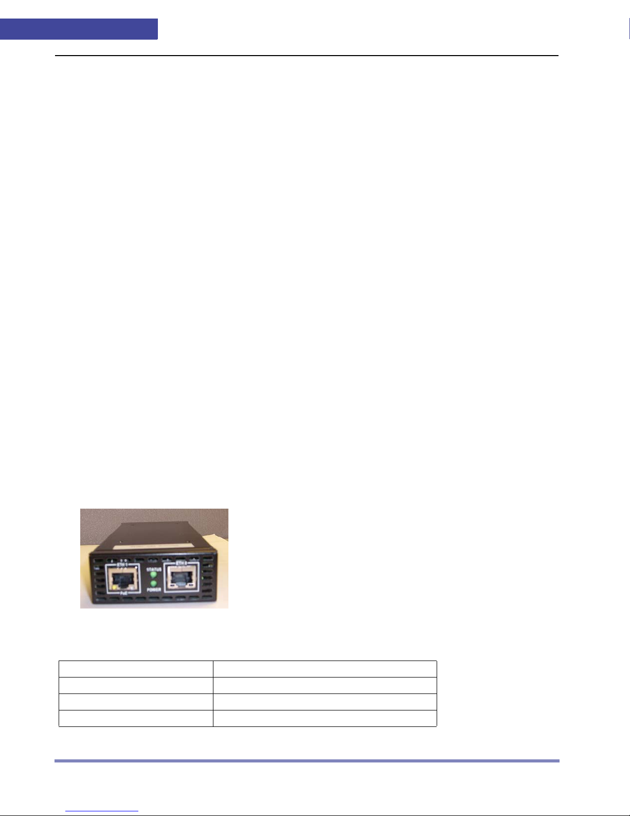
FSL100 Appliance
Figure 1-2 is an diagram of the FSL100 appliance ports.
Figure 1-2 FSL100 appliance
Table 1-7 shows the hardware specifications of the FSL100 appliance.
Table 1-7 FSL100 Hardware Specifications
FSL100 appliance. It includes the following topics:
Parameter Value
Interfaces 2 Gigabit Ethernet, 1000Base-T (RJ-45)
Dimensions (H/W/D) 1 3/8" x 3" x 6 3/4"
Weight 1.3 lbs
1-8 User Guide
GETTING STARTED
Parameter Value
Power Supply 100 to 240V AC, 50-60Hz
Operational Temperature 0 to 45ºC
Storage Temperature -25º to 70ºC
Humidity 5% to 85%
Max Power Consumption 15 Watts
Safety Compliance UL60950-I, EN60950, TUV
EMC Compliance FCC Class A, EN55022 Class A, VCCI Class A,
VCCI Class A, C-Ti ck, Immunity CN55024,
EN61000-3-2/3
LED Activity for FSL100
Table 1-8 lists information about the physical interfaces on the SlimLine 100 appliance.
Table 1-8 Physical Interfaces Table
Interface Name Interface Type Default Zone
eth0 Interface Copper 1000base-T Trust
eth1 Interface Copper 1000base-T
Untrust
. . . . .
For additional information on interface configuration refer to Security Zones and Interfaces on
page 9-1.
Table 1-9 shows the LED Status Description.
Table 1-9 LED Status Description
LED Behavior Meaning
Flashing Green System is starting up
Solid Green System is operating
Off System is not operating
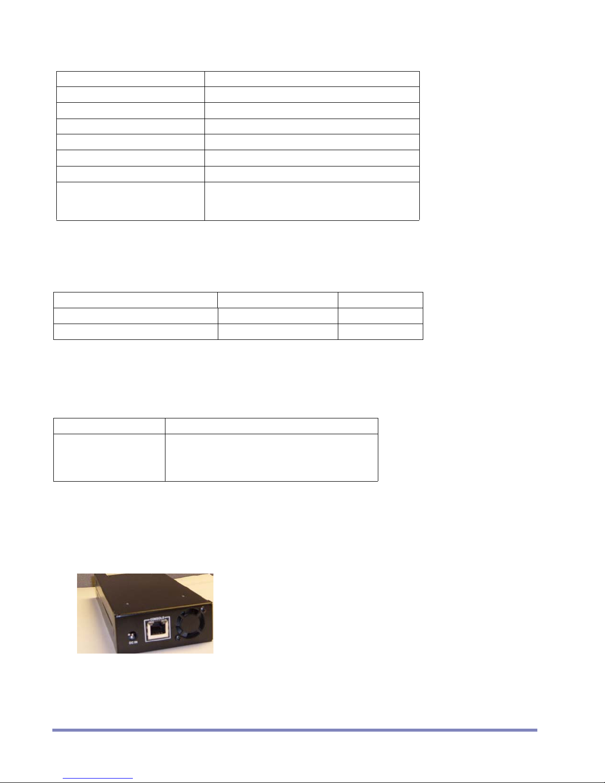
Console Interface for FSL100
Use the console cable provided to manage the FSL100 appliance through the console
interface. Figure 1-3 displays the location of the console interface on the back of the
appliance.
Figure 1-3 Console Back
FSL100
For additional information on console interface management refer to User Guide.
User Guide 1-9
1
GETTING STARTED
Slim 300M Appliance Specifications
This section describes the physical attributes, electrical information and environmental requirements to properly install and run the Slim 300M appliance. It includes the following topi cs:
• Slim 300M Appliance
• LED Activity for Slim 300M
•
Slim 300M Console Interface
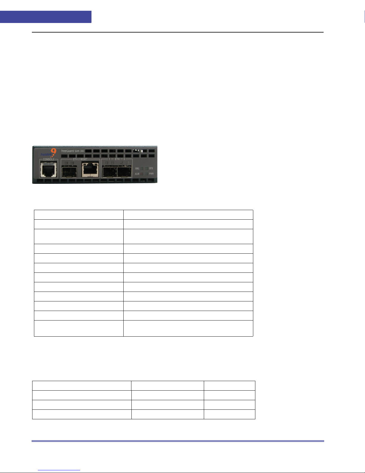
Slim 300M Appliance
The diagram of the Slim 300M appliance ports.
Figure 1-4 Slim 300M Appliance
Table 1-10 shows the hardware specifications of the Slim 300M appliance.
Table 1-10 Hardware Specifications
Parameter Value
Interfaces 2 mini GBIC (SFP)
Hardware Bypass Power failure, hardware or software failure
Dimensions (H/W/D) 5” x 10” x 1.5”
Weight 2 lbs
Power Supply 100 to 240V AC, 50-60Hz
Operational Temperature 0 to 45ºC
Storage Temperature -25º to 70ºC
Humidity
Max Power Consumption 15 Watts
Safety Compliance UL60950-I, EN60950, TUV
EMC Compliance
feature. Two interfaces: eth0 and eth1.
5% to 90% non-condensing
5% to 90% non-condensing, VCCI Class
A, C-Tick
LED Activity for Slim 300M
Table 1-11 lists information about the physical interfaces on the Slim 300M appliance.
Table 1-11 Physical Interfaces Table
Interface Name Interface Type Default Zone
eth0 Interface mini GBIC/SFP global
eth1 Interface mini GBIC/SFP
eth2 Management mini GBIC or RJ45 global
1-10 User Guide
global

GETTING STARTED
For additional information on interface configuration refer to Security Zones and Interfaces on
page 9-1.
Table 1-12 shows the LED Status Description.
Table 1-12 LED Status Description
LED Behavior Meaning
Flashing Green System is starting up
Solid Green System is operating
Off System is not operating
Slim 300M Console Interface
Use the console cable provided to manage the Slim 300M appliance through the console
interface.
Configuring the Software for the Appliances
. . . . .
T o configu re the the freedom9's appliance software for the first time, perform the steps described
in the following sections:
1. Changing the Admin Password.
2. Default Configuration.
3. Configuring the Default Route for Management Traffic.
4. Viewing the Policy Configuration.
Changing the Admin Password
Because all freedom9's appliances are preconfigured with the same password, you must
change the admin password.
Use the set admin command to change the password:
set admin password {password_str}
save
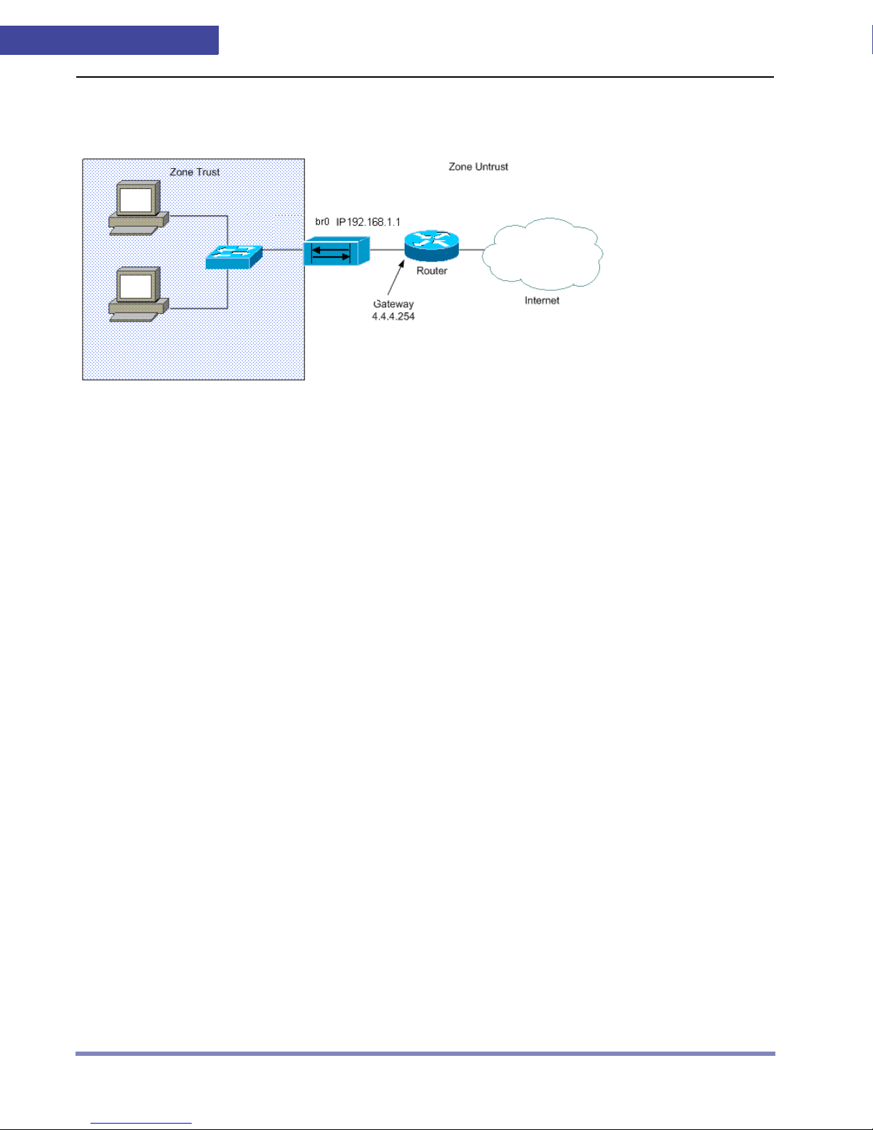
Default Configuration
The freedom9's appliance is configured to monitor a network such as the one displayed in
Figure 1-5. In this configuration, the eth0 interface is connected to the inside LAN Switch and the
eth1 interface is connected to your Internet router . The eth0 interface is bound t o the zone
and the eth1 interface is bound to the zone untrust and both interfaces are configured in
trust
User Guide 1-11
1
transparent mode. The management IP address is 192.168.1. 1 and is accessible via web browser
over HTTP. This allows you to manage policies between the zones.
Figure 1-5 Network Protection
To view the interface settings, use the get interface command
get interface {eth0|eth1}
GETTING STARTED
Configuring the Default Route for Management Traffic
Use the set route command to configure the default route for management traffic. The set route
command consists of the destination network, the interface name, and the IP address to forward
packets from that interface.
Using the network in Figure 1-5 as an example, use the set route command to configure the
Freedom9 appliance to use the address of 192.168.2.254 for the default route of all traffic
set route 0.0.0.0/0 interface br0 gateway 192.168.2.254
save
Optional: To verify the default route settings execute the get route summary command:
get route summary
Viewing the Policy Configuration
Use the get config command to view the policy configuration:
get config
This command returns the following information, which is based on the network diagram in Figure
1-5.
(Interfaces)
set interface eth0 ip transparent
set interface eth0 zone trust
set interface eth1 ip transparent
set interface eth1 untrust
set interface br0 192.168.1.1
1-12 User Guide

GETTING STARTED
(Route)
set route 0.0.0.0/0 interface br0 gateway 192.168.1.254
Configuring a Policy
The default policy behavior is set policy default permitted.
See Advanced Policy Configuration on page 6-1 for more information about policy configuration.
. . . . .
User Guide 1-13

1
GETTING STARTED
1-14 User Guide

System
SYSTEM MANAGEMENT
. . . . .
Management
This chapter describes the management options for freedom9's appliances, including
software management, system management, and user account management. The following
topics are included in this chap ter:
• Using the Console to Manage the
• Using SSH to Manage the
• Managing Users for the
• Managing Software for the
• Resetting and Restarting the
• Additional System Management Tasks
• Using Network Time Protocol (NTP)
• Using Domain Name Service (DNS)
• Using Ping
• Using Traceroute
freedom9's Appliance
freedom9's Appliance
freedom9's Appliance
freedom9's Appliance
freedom9's Appliance
2
User Guide 2-1

2
SYSTEM MANAGEMENT
Using the Console to Manage the Freedom9's Appliance
The serial console interface can be used fo r in it i al c o nf i gu ration of the Freedom9' s
appliance. Alternatively, the web interface or SSH can also be used for initial configuration since
the appliance has a default IP address of 192.168.1.1.
After you configure the
using a secure shell (SSH). This section describes how to work with the console and i ncludes the
following topics:
• Viewing Console Interface Settings
• Setting the Console Display
• Setting the Console Timeout
• Exiting the Console
Viewing Console Interface Settings
To view current console interface settings, including users who are logged in and to display
information for the console interface, us e the get console command:
get console
Freedom9's appliance, you can manage it through the console or by
Setting the Console Display
Use the set console command to set the number of lines to display without a break. If the page
display number is set to 0, no page breaks are used when information is displayed. The default
display number is 22 lines for each page.
set console page {number}
Example: Setting the Console Page Display to 50
set console page 50
save
Setting the Console Timeout
To set the in ac ti v ity value for the console interface, use the set console command with the
timeout option. The timeout value is represented in minutes. The default inactivity timeout is 10
minutes.
set console timeout {number}
Example: Setting the Console Timeout to 15 Minutes
set console timeout 15
save
Exiting the Console
To exit the console, type exit.
2-2 User Guide

SYSTEM MANAGEMENT
Using SSH to Manage the Appliance
For secure remote management of the appliance, use an SSH program.
Enabling SSH on a Specific Interface
You can enable SSH management on any interface. To enable SSH on a specific interface, use set
ssh command with the interface option:
set interface {interface name} manage ssh
Example: Enabling SSH on the br0 Interface
set interface br0 manage ssh
save
GUI Example: Enabling SSH on the ETH0 Interface
1. Select Network > Interface > Edit (for ethernet0)
. . . . .
2. Select the following, then click Apply:
Management Option: SSH
Example: Enable SSH on a VLAN Interface eth0.100
set interface eth0.100 manage ssh
save
GUI Example: Enable SSH on a VLAN Interface ETH0.100
1. Select Network > Interface > Edit (for ethern et0.100)
2. Select the following, then click Apply:
Management Option: SSH
Disabling SSH on a Specific Interface
To disable SSH on a specific interface, use the unset ssh command:
unset interface {interface name} manage ssh
Viewing SSH Settings
To view users who log in using SSH or to view the host key currently used for SSH, use the get
ssh command:
get ssh {host-key}
Generating New SSH Host Keys
The Freedom9 appliance already comes with an SSH host key . Use the exec ssh command
to generate an SSH host key:
User Guide 2-3

2
exec ssh gen-hostkey
SYSTEM MANAGEMENT
Managing Users for the Freedom9 Appliance
The Freedom9 appliance has a single global administrator account with the user name
admin. This account has the following administrative privil eges:
• Add, remove, and manage security zones
• Assign interfaces to security zones
• Reset the device to its default settings
• Update the firmware
• Load configuration files
• Clear all active sessions
• Change the password for the admin and admin-r (read-only user)
Changing Your Administrator Password
Since all Freedom9 appliances come pre-configured with the same password, you must
change the admin password to create a unique password for your organization. Use the
set admin command:
set admin password {password_str}
[NOTE]
You cannot change the administrator user name “admin.”
GUI Example: Changing the Administrator password
1. Select System > Admin > Administrators.
2. Enter the following password information and click Apply.
3. Select the admin user.
4. Type old password.
5. Type new password.
6. Confirm new password.
About Additional Types of Users
The Freedom9 appliance can support one additional user, called “admin-r,” with read-only
access to the management interface.
Changing the Admin-r Password
To change the admin-r password, use the set admin-r command:
set admin-r password {password_str}
[NOTE]
GUI Example: Changing the Admin-r password
2-4 User Guide
You cannot change the user name “admin-r.”
1. Select System > Admin > Administrators.

2. Enter the following password information and click Apply.
3. Select the admin-r user.
4. Type old password.
5. Type new password.
6. Confirm new password.
SYSTEM MANAGEMENT
. . . . .
User Guide 2-5

2
SYSTEM MANAGEMENT
Managing Software for the Appliance
To prepare for upgrading your appliance software using the CLI/SSH, review
the following list. To upgrade the software using the Web UI, see Upgrading the Software Using
the Web User Interface on page 2-7.
• Admin privilege to access the
• A console connection or SSH session to manage
• An installed and running TFTP server on your computer or have access through the Web
user interface.
appliance.
the appliance.
• An Ethernet connection to the
appliance exists (You use this connection
to transfer software from the TFTP server to the appliance flash memory).
• Route must exist to the TFTP server.
• You must meet license requirements.
Storing Software Image Files in Flash Memory
The appliance can store the following software image files in flash memory:
• New software image
• Currently saved software image
• Factory default software image
Downloading New Software
Please contact your support portal for the latest software images.
Uploading New Software
To upload new software for the appliance:
1. Make sure you have the latest version of software for th e appliance. This can be
obtained from your sales representative .
2. Place a copy of the latest software for the appliance into the root directory of the
TFTP server program.
3. Make sure a TFTP server is running on a PC and the appliance can access it.
4. Log in as admin on the appliance using an application such as SSH or
HyperTerminal if directly connected through the console port.
5. On the appliance, enter save software from tftp ip_addr filename mos {pri | sec},
where the ip_addr is the IP address of your computer and filename is the file name of the
appliance software. In addition you must specify either the primary or secondary image
location (pri | sec). This will download the image from the TFTP server to the primary or secondary
location.
6. After saving the image to either the primary or secondary slot, execute the set image
nextboot {pri | sec} command to set it as the active image.
7. Reset the Freedom9 appliance by executing the reset command and entering y at the prompt.
8. Log in to the Freedom9 appliance.
2-6 Appliance User Guide
Freedom9
 Loading...