

Freedom9 freeView IP 100 User Manual

freeView IP 100
Single Port KVM over IP SWITCH
USER’S MANUAL
Rev 1.4
P/N: KVM-01IA

Copyright and Trademark Information
This document contains proprietary information that is protected by copyright. All rights reserved.
No part of this document may be photocopied, reproduced, or translated into another language
without express prior to written consent of freedom9 inc.
© Copyright 2005, freeView IP and the freedom9 company logo are trademarks or registered
trademarks of freedom9 inc. All rights reserved. Sun and Java are trademarks or registered
trademarks of Sun Microsystems, Inc. Internet Explorer, Windows Explorer, Windows, and
HyperTerminal are trademarks or registered trademarks of Microsoft Corporation. Netscape and
Netscape Navigator are trademarks or registered trademarks of Netscape Communication
Corporation. Other trademarks or registered trademarks are the property of their respective
holders.
2

freeView IP 100 User’s Manual
TABLE OF CONTENTS
1 QUICK INSTALLATION GUIDE...........................................................................................................3
1.1 INTRODUCTION...............................................................................................................................3
1.2 HARDWARE INSTALLATION...............................................................................................................3
1.3 VIDEO MODES ...............................................................................................................................3
1.4 INITIAL IP CONFIGURATION..............................................................................................................4
1.5 WEB INTERFACE ............................................................................................................................5
1.6 REMOTE CONSOLE.........................................................................................................................5
2 INTRODUCTION..................................................................................................................................7
2.1 WHEN THE SERVER IS OPERATIONAL..............................................................................................7
2.2 WHEN THE SERVER IS NON-OPERATIONAL......................................................................................7
2.3 FEATURES .....................................................................................................................................8
2.4 PACKAGE CONTENTS......................................................................................................................8
2.5 TECHNICAL SPECIFICATIONS...........................................................................................................9
2.6 SYSTEM REQUIREMENTS ................................................................................................................9
2.7 CABLE DIAGRAMS ........................................................................................................................10
3 HARDWARE INSTALLATION ...........................................................................................................11
3.1 OPERATION OVERVIEW.................................................................................................................1 1
3.2 CONNECTING THE FREEVIEW IP 100 TO THE HOST SYSTEM..........................................................11
3.3 ETHERNET CONNECTION ..............................................................................................................14
3.4 CONNECTING THE FREEVIEW IP 100 TO A MULTI-PORT KVM SWITCH............................................15
3.5 CONNECTING THE EXTERNAL RESET/POWER OPTION....................................................................15
4 CONFIGURATION .............................................................................................................................16
4.1 INITIAL CONFIGURATION................................................................................................................16
4.2 INITIAL CONFIGURATION VIA DHCP SERVER..................................................................................16
4.3 FREEVIEW IP 100 SETUP PROGRAM .............................................................................................16
4.4 INITIAL CONFIGURATION VIA SERIAL CONSOLE...............................................................................17
4.5 KEYBOARD, MOUSE AND VIDEO CONFIGURATION ..........................................................................18
5 USAGE...............................................................................................................................................22
5.1 PREREQUISITES...........................................................................................................................22
5.2 HTTP/HTTPS.............................................................................................................................22
5.3 LOGGING IN AND LOGGING OUT....................................................................................................23
5.4 THE REMOTE CONSOLE................................................................................................................25
5.5 MAIN WINDOW.............................................................................................................................26
1

MENU OPTIONS................................................................................................................................35
6
6.1 REMOTE CONTROL.......................................................................................................................35
6.2 VIRTUAL MEDIA............................................................................................................................37
6.3 USER MANAGEMENT ....................................................................................................................49
6.4 KVM SETTINGS ...........................................................................................................................50
6.5 DEVICE SETTINGS........................................................................................................................56
6.6 MAINTENANCE .............................................................................................................................68
7 TROUBLESHOOTING.......................................................................................................................72
7.1 CERTIFICATES..............................................................................................................................73
A. PIN ASSIGNMENTS..........................................................................................................................74
B. KEY CODES ......................................................................................................................................75
C. VIDEO MODES..................................................................................................................................78
D. RACK MOUNT KIT INSTALLATION DIAGRAM...............................................................................78
2

freeView IP 100 User’s Manual
LIST OF FIGURES
Figure 1-1: The Host and Console Connectors............................................................................................5
Figure 1-2: KVM Setup Program...................................................................................................................6
Figure 1-3: Java Warning..............................................................................................................................8
Figure 1-4: Remote Console.........................................................................................................................8
Figure 3-1a: Single Server Usage Scenario ...............................................................................................13
Figure 3-1b: Multiple Server Usage Scenario.............................................................................................13
Figure 4-1: Setup Utility...............................................................................................................................19
Figure 5-1: Encryption Key Length in Internet Explorer..............................................................................25
Figure 5-2: Login Screen.............................................................................................................................25
Figure 5-3: Main Page.................................................................................................................................26
Figure 5-4: Remote Console.......................................................................................................................27
Figure 5-5: Remote Console Control Bar....................................................................................................28
Figure 5-6: Remote Console Options Menu ...............................................................................................29
Figure 5-7: Remote Console Exclusive Mode.............................................................................................30
Figure 5-8: Remote Console Options Menu – Scaling ...............................................................................30
Figure 5-9: Remote Console Options Menu – Local Cursor.......................................................................31
Figure 5-10: Video Settings Panel..............................................................................................................32
Figure 5-11: Soft Keyboard .........................................................................................................................33
Figure 5-12: Soft Keyboard Mapping..........................................................................................................34
Figure 5-13: Remote Console Confirmation Dialog....................................................................................35
Figure 5-14: Encoding.................................................................................................................................35
Figure 5-15: St atus Line..............................................................................................................................36
Figure 5-16: Bandwidth Usage....................................................................................................................36
Figure 6-1: KVM Console............................................................................................................................37
Figure 6-2: Telnet Console..........................................................................................................................38
Figure 6-3: Virtual Floppy Disk Screen.......................................................................................................39
Figure 6-4: Select Image File......................................................................................................................40
Figure 6-5: Virtual CD-ROM Image Screen................................................................................................41
Figure 6-6: Select Windows Share .............................................................................................................41
Figure 6-7: Windows Explorer Context Menu.............................................................................................42
Figure 6-8: Share Configuration Dialog ......................................................................................................42
Figure 6-9: RawWrite for Windows Selection Dialog..................................................................................44
3

Figure 6-10: Nero Selection Dialog.............................................................................................................45
Figure 6-11: Drive Redirection Menu ..........................................................................................................45
Figure 6-13: Create a New Device..............................................................................................................48
Figure 6-14: Device Configuration Dialog...................................................................................................48
Figure 6-15: New Device Added.................................................................................................................49
Figure 6-16: Drive Redirection Setting........................................................................................................49
Figure 6-17: Drive Redirection Dialog.........................................................................................................49
Figure 6-18: Drive Redirection Completed..................................................................................................50
Figure 6-19: USB Mass Storage Option......................................................................................................50
Figure 6-20: Set Password..........................................................................................................................51
Figure 6-21: Set User..................................................................................................................................52
Figure 6-22: User Console Settings (Part 1)...............................................................................................53
Figure 6-22: User Console Settings (Part 2)...............................................................................................54
Figure 6-23: Keyboard and Mouse Settings ...............................................................................................56
Figure 6-24: Video Settings.........................................................................................................................57
Figure 6-25: Network Settings ....................................................................................................................59
Figure 6-26: Dynamic DNS.........................................................................................................................60
Figure 6-27: Dynamic DNS Scenario..........................................................................................................61
Figure 6-28: Device Security.......................................................................................................................62
Figure 6-29: Certificate Settings .................................................................................................................63
Figure 6-30: SSL Certificate Upload...........................................................................................................64
Figure 6-31: Serial Port...............................................................................................................................65
Figure 6-32: Date and Time........................................................................................................................67
Figure 6-33: Event Log................................................................................................................................68
Figure 6-34: Device Information..................................................................................................................70
Figure 6-35: Connected Users....................................................................................................................70
Figure 6-36: Event Log List.........................................................................................................................71
Figure 6-37: Update Firmware....................................................................................................................71
Figure 6-38: Unit Reset...............................................................................................................................73
Figure B-1: English (US) Keyboard Layout.................................................................................................78
Figure D-1: Rack Mount Installation Diagram.............................................................................................79
4
freeView IP 100 User’s Manual
1 QUICK INSTALLATION GUIDE
1.1 Introduction
The freeView IP 100 redirects local keyboard, mouse and video data to a remote administration
console. All data is transmitted via internet protocol (IP). The unit can also be used in a multi
administrator and multi server environment. In addition, the unit is a KVM switch, which can also
be used with a local console (a local set of monitor, keyboard, and mouse).
1.2 Hardware Installation
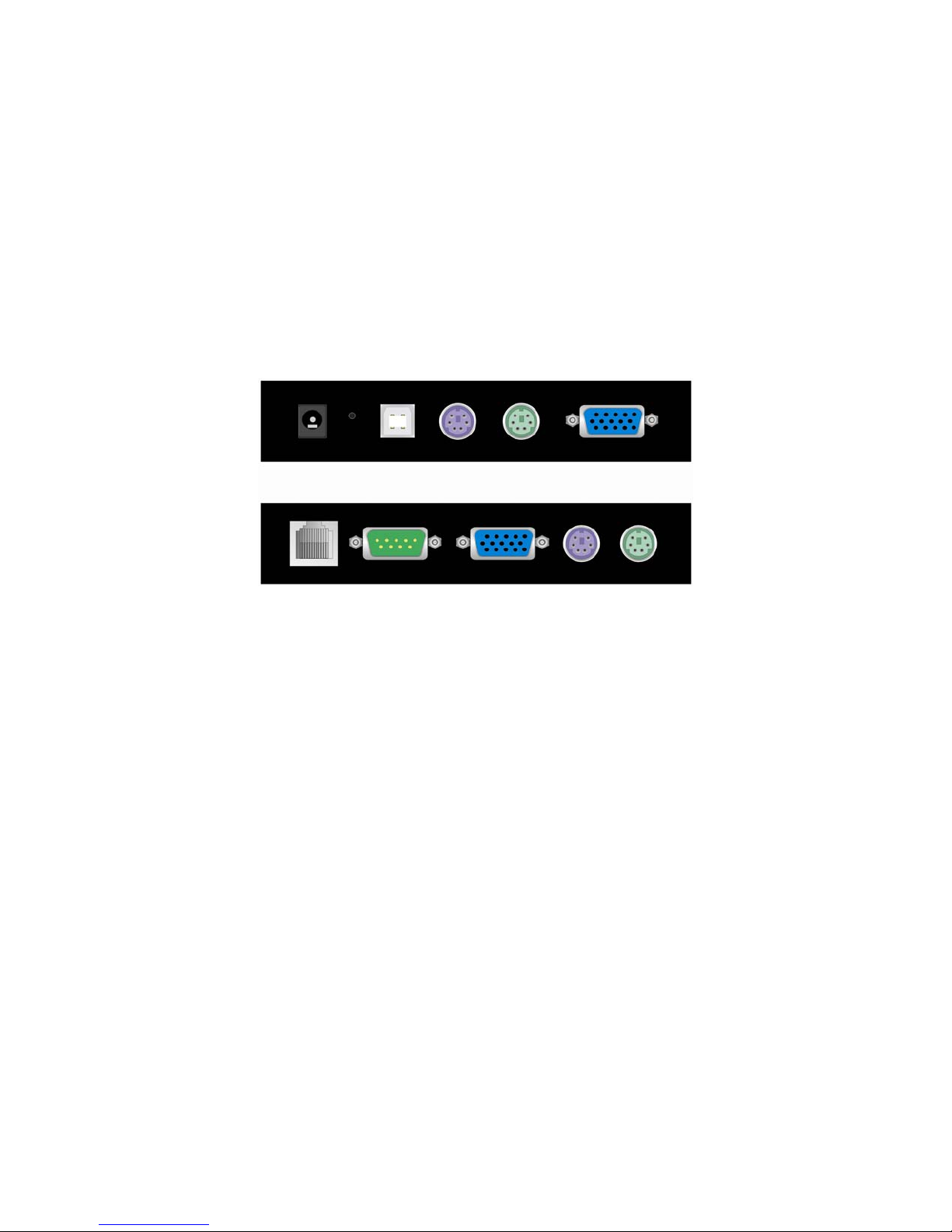
Host
Console
Figure 1-1: The Host and Console Connectors
1. Power off the server.
2. Remove the unit from the box.
3. Connect the included KVM cable from the server to the port s labeled Host on the unit. (Check
that the keyboard and mouse connectors are connected to the proper ports and are not
crossed.)
4. If a local console is being used, connect the local monitor, mouse, and keyboard to the ports
labeled Console on the unit.
5. If a remote mass storage device is being used, connect the included USB cable from the
server to the USB port on the unit.
6. Connect an Ethernet cable to the LAN port and/or modem to RS-232 serial port, depending
on how the unit will be accessed.
7. Power on the unit.
8. Power on the server.
1.3 Video Modes
The freeView IP 100 supports many common video modes. Please refer to Appendix C for a list
of all supported video modes.
5
1.4 Initial IP Configuration
By default, the freeView IP 100 uses the network parameters shown in Table 1-1.
Parameter Value
IP auto configuration Static
IP-Address 192.168.1.22
Net-mask 255.255.255.0
Default-Gateway None
Table 1-1: Default network configuration
If these network parameters do not match the network configuration, the device's network
settings can be configured using the program KVMSetup.exe located on the installation CD after
the unit has been connected to the network and powered on.
To change the network settings of the device:
1. Open Windows Explorer and browse to the CD drive.
2. Double-click the file KVMSetup.exe.
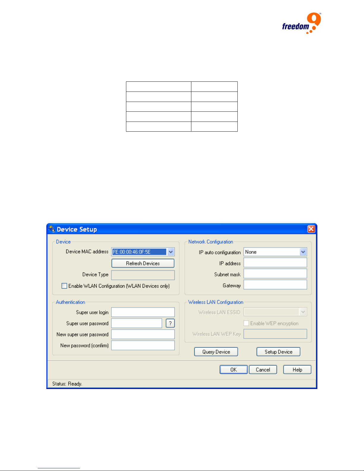
3. A screen similar to Figure 1-2 will be displayed.
4. Select the unit’s MAC address from the drop-down list under “Device MAC address”.
5. Enter the desired IP address for the device under “Network Configuration”.
Figure 1-2: KVM Setup Program
6

freeView IP 100 User’s Manual
6. Enter the user name and password under “Authentication”. The default user name is
“super” and the default password is “pass”.
7. Click “Setup Device”.
1.5 Web Interface
Once the device has been configured to match the network setup, log in to the web interface
using a Java enabled web browser. Once the web browser is running, enter “http://<device IP
address>” in the browser window (e.g. if the device’s IP address is 192.168.1.22, type
“http://192.168.1.22” in the browser window).
The default user name and password to log into the device are shown below.
User name super
Password pass
It is recommended that the default password be changed immediately to prevent unauthorized
access to the device.
1.6 Remote Console
The Remote Console is the redirected screen, keyboard and mouse of the remote host system to
which the freeView IP 100 is connected. The web browser which is u sed to access th e unit has to
have Java Runtime Environment version 1.1 or higher installed. However, it is strongly
recommended that the Sun JVM 1.4 is installed.
To access the remote console of the host, click the Console icon on the top-left corner of the
screen. There may be a slight delay as the Java virtual applet is being loaded. If the screen
shown in Figure 1-3 appears, click “Yes”.
7
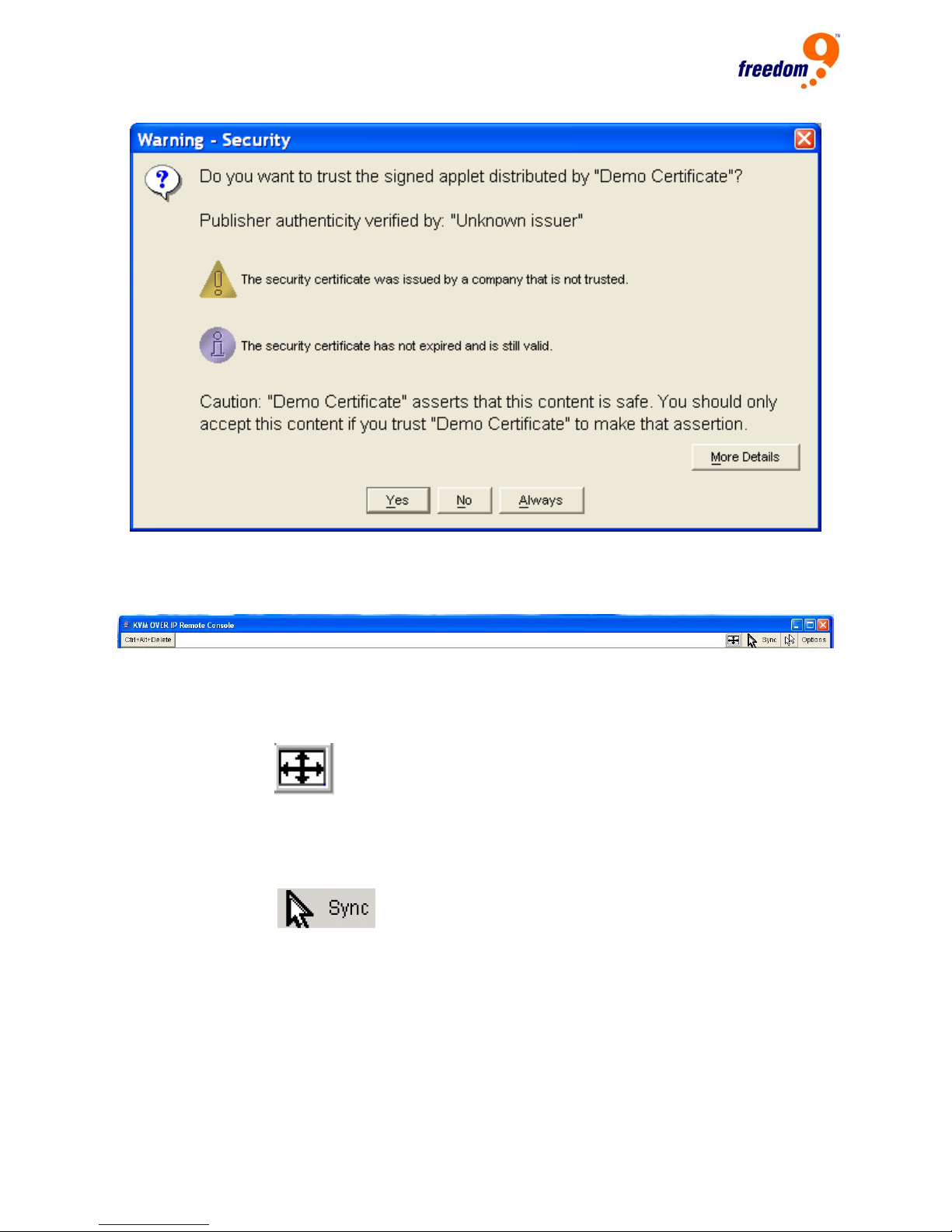
Figure 1-3: Java Warning
Figure 1-4 shows the top of the Remote Console window.
Figure 1-4: Remote Console
Once connected, the following can be performed to improve the user experience:
Auto Adjust button
If the video displayed is distorted, click this button and the device will automatically adjust its
display to improve the quality.
Sync Mouse button
Choose this option in order to synchronize the local with the remote mouse cursor. This is only
required if using Double Mouse mode. It is recommended that mouse acceleration is turned off
on the host device.
8

freeView IP 100 User’s Manual
2 Introduction
Thank you for purchasing the freeView IP 100. The freeView IP 100 sa ves money, time, space,
equipment and power. The freeView IP 100 defines a new class of remote KVM access devices,
it combines digital remote KVM access via IP networks with comprehensive and integrated
system management.
The device provides convenient, remote KVM access and control via LAN or Internet. It captures,
digitizes, and compresses the video signal and transmits it with keyboard and mouse signals to
and from a remote computer. The freeView IP 100 provides a non-intrusive solution for remote
access and control. Remote access and control software runs on the embedded processor only
and not on the mission-critical servers, so that there is no impact on server or network
performance.
Furthermore, the freeView IP 100 offers additional remote power management when used with
an optional IP Power device.
The device supports consoles consisting of a PS/2 keyboard and mouse and HDDB 15 video
output and will automatically detect the current video mode of the console. The freeView IP 100
will accept video streams up to 110 MHz. This results in a screen resolution of 1280x1024 pixels
with a frame rate of 60 Hz.
2.1 When The Server Is Operational
The freeView IP 100 gives you full control over the remote server. The Management Console
allows you to access the remote server’s graphics, keyboard and mouse and the ability to send
special commands to the server. You can also perform periodic maintenance on the server.
Using the Remote Console, you can do the following:
A. Reboot the system.
B. Monitor the boot process.
C. Boot to a different operating system on dual-boot machines.
D. Boot up in Windows Safe Mode.
E. Boot the system from a separate partition to load diagnostic environment.
F. Run special diagnostic programs.
2.2 When The Server Is Non-Operational
Using the freeView IP 100, the system administrator can discover problems with the server,
though fixing hardware problems is not possible through a remote management device.
Nevertheless, the device gives the administrator valuable information about the type of hardware
failure. Serious hardware failures can be categorized into five different categories, with the
percentage chance of failure listed below:
A. Hard disk failure 50%
9

B. Power cable detached, power supply failure 28%
C. CPU, Controller, main board failure 10%
D. CPU fan failure 8%
E. RAM failure 4%
Using the freeView IP 100, administrators can determine which kind of serious hardware failure
has occurred (See table 2-1).
Type of Failure Detected By
Hard disk failure Console screen, CMOS set-up information
Power cable detached, power supply failure Server remains in power off state after power on
command has been given.
CPU Controller, main board failure. Power supply is on, but there is no video output.
CPU fan failure Server specific management software
RAM failure Boot-sequence on boot console
Table 2-1 Host System Failures and Detection Methods
2.3 Features
• Manage servers around the world from your desk
• KVM (keyboard, video, mouse) access over IP and analog telephone line (modem required)
• BIOS level access
• SSL encryption
• No impact on server or network performance
• High-performance mouse tracking and synchronization
• Port to connect a user console for direct analog access to KVM switch
• Local Mouse suppression (only when using Sun’s Java Virtual Machine)
• Can be used with any standard KVM
• Remote mass storage control
2.4 Package Contents
freeView IP 100 1 PC
Quick Install Guide 1 PC
Installation software and User Manual on CD-ROM 1 PC
AC to DC Power Adapter 1 PC
Rack mount Kit 1 SET
10

freeView IP 100 User’s Manual
Null modem cable 1 PC
USB A to B 6 feet cable 1 PC
3-in-1 3 feet KVM cable 1 PC
2.5 Technical Specifications
Model No. freeView IP 100
PC Port 1
Console Port 1
PC Port Connector
(All Female Types)
Console Port Connector
(All Female Types)
Remote Console Connector RJ-45 8P8C
Serial Port (DB9 pin Male) 1
LAN port (RJ-45 8P8C) 1 x 10BASE-T Ethernet
Reset button 1
Keyboard Emulation PS/2
Mouse Emulation PS/2
VGA Resolution Local: 1600X1200 Remote: 1280X1024
Housing Metal
Power Adapter DC 5V, 2.5A
Operation Temperature 0 ~ 5°C
Storage Temperature -20 ~ 60°C
Humidity 0 ~ 80%, Non-Condensing
Size Desktop
Weight (kg) 1700g
Dimension (mm) 156 X139 X 27
PS/2 Keyboard Mini Din 6 pin
PS/2 Mouse Mini Din 6 pin
VGA HDDB 15 pin
USB Type B receptacle
PS/2 Keyboard Mini Din 6 pin
PS/2 Mouse Mini Din 6 pin
VGA HDDB 15pin
1 x 100BASE-T Ethernet
2.6 System Requirements
Item Description
Local console side One PS/2 Keyboard, one PS/2 Mouse and one monitor
Remote Console side One PC or Multiple PCs are linked into the network
Host side One PC or Server or the console port of another KVM switch
11
2.7 Cable Diagrams
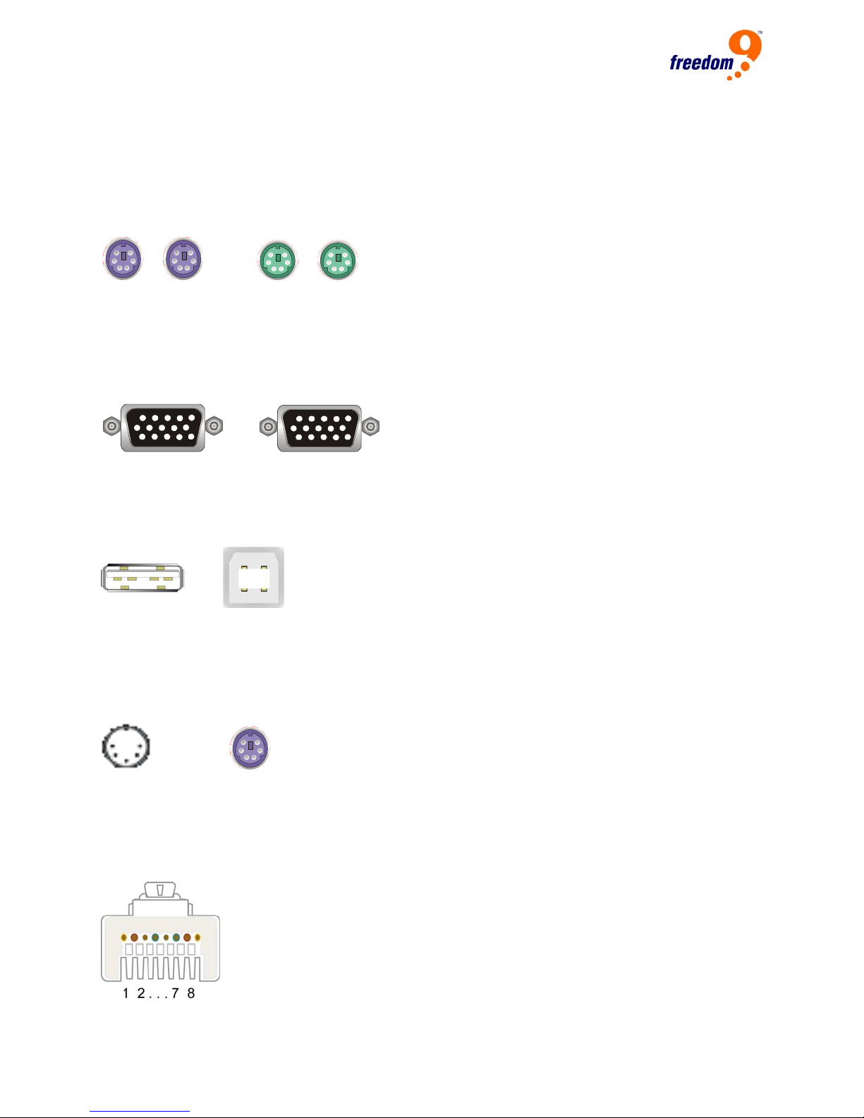
PS/2 Cable:
Mini Din 6 pin Male to Male
VGA Cable:
HDB15 pin Male to Male
USB 2.0 Cable:
USB A-B cable
AT to PS/2 keyboard adapter: (Optional)
Din 5 pins Male to Mini Din 6 pin Female
CAT5/5E/6 Straight Through UTP/STP Cable:
8P8C
12
freeView IP 100 User’s Manual
3 Hardware Installation
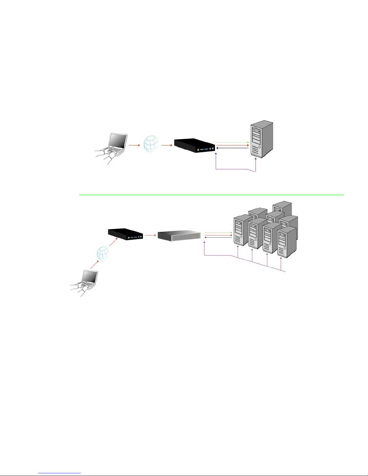
3.1 Operation Overview
Figure 3-1 shows some examples of how to connect the freeView IP 100 to the local area
network.
freeView IP
PC
IP Network
Administrator
Figure 3-1a: Single Server Usage Scenario
freeView IP
8/16 PS/2
IP Network
Administrator
KVM Switch Multiple
Servers
Figure 3-1b: Multiple Server Usage Scenario
The freeView IP 100 can be used in a multi-administrator, multi-server environment. Attaching
one or several units to a matrix KVM switch allows multiple users to access multiple servers
using the remote console.
3.2 Connecting The freeView IP 100 To The Host System
In order to connect the device to the host system, perform the following steps:
Step 1
Connect the VGA cable on one end a KVM cable to the monitor port on the host system and the
VGA cable on the other end of the cable to the monitor port on the host side of the unit.
13
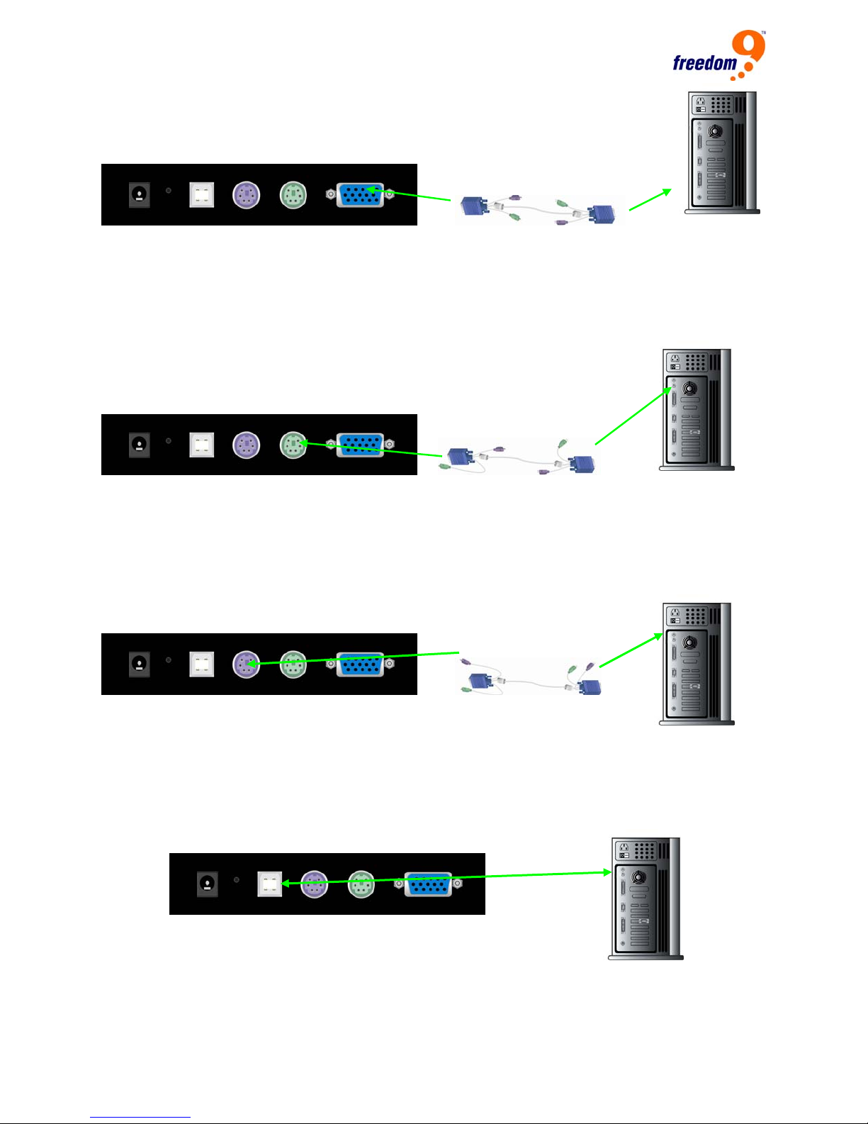
Step 2
Connect the green PS/2 plug on one end of a KVM cable to the mouse port on the host system
and the green PS/2 plug on the other end of the cable to the mouse port on the host side of the
unit.
Step 3
Connect the purple PS/2 plug on one end of a KVM cable to the keyboard port on the host
system and the purple PS/2 plug on the other end of the cable to the keyboard port on the host
side of the unit.
Step 4 (Only required if using Virtual Media)
Connect the type A connector of a USB A-B cable to the USB port on the host system and the
type B connector to the unit.
14
freeView IP 100 User’s Manual
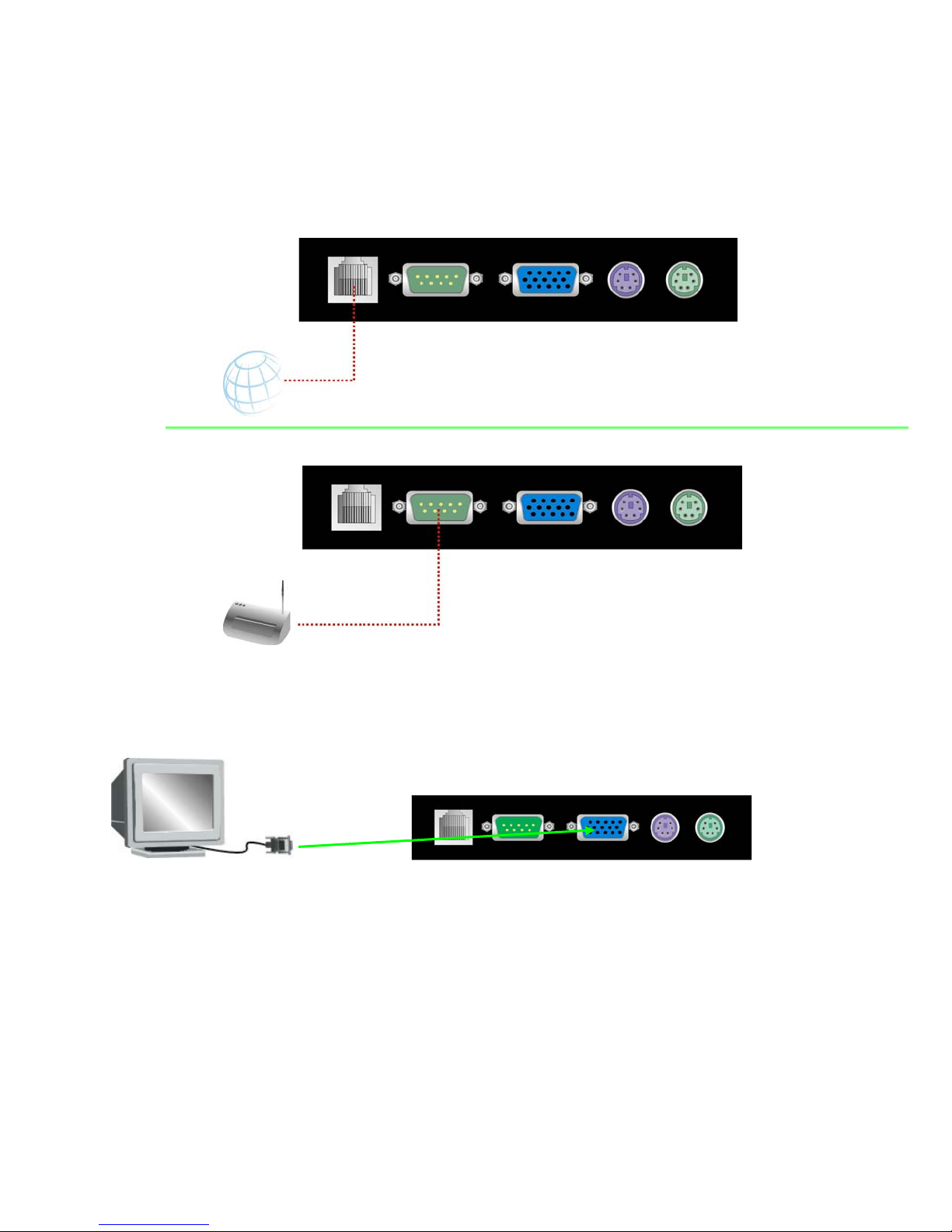
Step 5
Connect an Ethernet cable to the Ethernet port on the unit and/or connect a modem to the DB-9
port on the unit, depending on how the KVM is accessed remotely.
INTERNET
Modem
Step 6 (Only required if using a local console)
Connect the monitor to the monitor port on the console side.
15
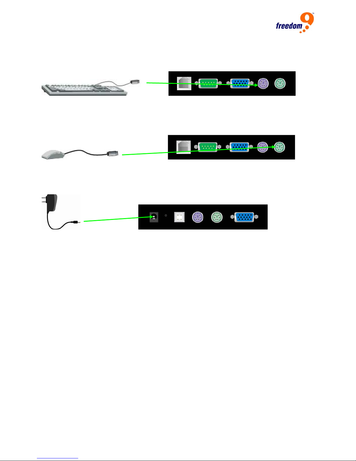
Step 7 (Only required if using a local console)
Connect the keyboard to the PS/2 port marked as keyboard on the console side.
Step 8 (Only required if using a local console)
Connect the mouse to the PS/2 port marked as mouse on the console side.
Step 9
Connect the power supply on to the freeView IP 100.
3.3 Ethernet Connection
The rear side of the freeView IP 100 provides a RJ-45 connector for a 10/100 Mbps Ethernet
connection.
Using a 10 Mbps Connection
For 10BASE-T Ethernet networks, the Ethernet adapter uses Category 3, 4, 5 or 6 UTP cable. To
establish a 10 Mbps connection, the cable must be connected to a 10BASE-T hub.
• Make sure that the cable is wired appropriately for a standard 10BASE-T adapter.
• Align the RJ-45 plug with the notch on the adapter’s connector and insert it into the adapter’s
connector.
Using a 100 Mbps Connection
For 100BASE-TX Fast Ethernet networks, the freeView IP 100 supports Category 5 or higher
UTP cabling. To establish a 100 Mbps connection, the cable must be connected to a
100BASE-TX hub or switch.
16

freeView IP 100 User’s Manual
• Make sure that the cable is wired appropriately for a standard 100BASE-TX adapter.
• Align the RJ-45 plug with the notch on the adapter’s connector and insert it into the adapter’s
connector.
3.4 Connecting The freeView IP 100 To A Multi-Port KVM Switch
3.5 Connecting The External Reset/Power Option
Refer to the manual of the IP Power or Serial over IP device for instructions on connecting them
to the serial interface on the rear of the freeView IP 100.
17

4 Configuration
4.1 Initial Configuration
The freeView IP 100 is shipped with the network configuration listed in Table 4-1.
Parameter Value
IP auto configuration DHCP
IP-Address None
Net-mask 255.255.255.0
Default-Gateway None
Table 4-1: Initial Network Configuration
Note: If the freeView IP 100 cannot find a DHCP server on startup, it will not have an IP address.
The following describes the initial IP configuration that is necessary to access the unit for the first
time. Note: Before installation, make a note of the MAC address of the unit before installing the
device, it is located on the label on the bottom of the unit.
4.2 Initial Configuration Via DHCP Server
By default, the freeView IP 100 will attempt to obtain an IP address from a DHCP server on the
network. To determine the IP address obtained via DHCP, either check the list of assigned IP
addresses on the DHCP server and find the IP address assigned to the MAC address of the unit,
or set the DHCP server to assign a fixed IP address to the MAC address of the device. Consult
the manual for the DHCP server for detailed configuration instructions.
Alternatively, the setup tool KVMSetup.exe found on the Installation Disk accompanying the
product can also be used to set up the unit.
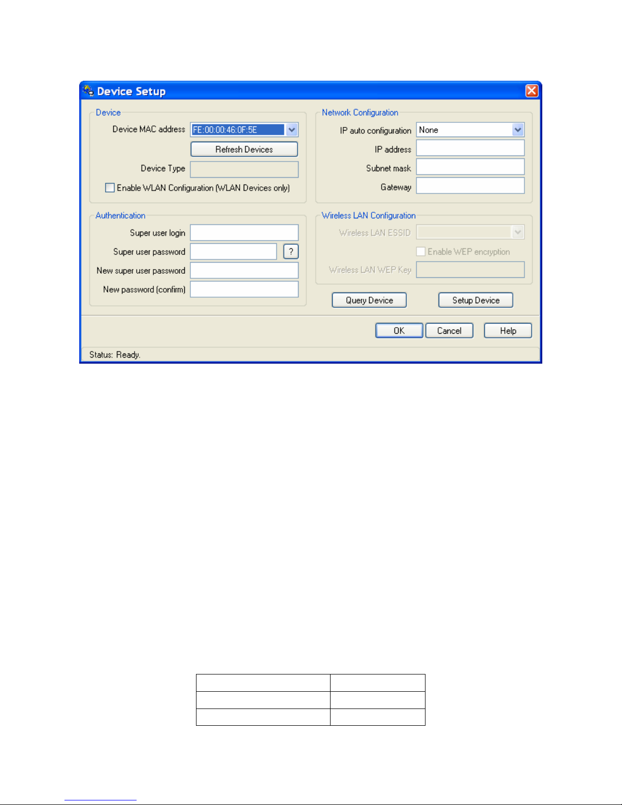
4.3 freeView IP 100 Setup Program
Connect the freeView IP 100 to a computer via local network or USB. Start the setup tool
KVMSetup.exe located on the Installation Disk on the computer. The program screen is shown in
Figure 4-1.
18
freeView IP 100 User’s Manual
Figure 4-1: Setup Utility
On the upper left corner, the MAC address(es) of all freeView IP 100 switches are displayed. To
rescan for devices, click “Refresh Devices”.
1. Select the MAC address of the unit to be configured from the dropdown list.
2. Click “Query Device” to populate the current configuration of the device.
3. Enter the network configuration settings in the Network Configuration screen.
4. Enter the username and password of the device in the Authentication screen. The default
username is “super” and the default password is “pass”.
5. If desired, enter a new password for the super user. Note: Write down the new password and
keep it in a safe, secure location for later reference.
6. Click “Setup Device” to save the new settings.
7. Click “OK” to close the window.
4.4 Initial Configuration Via Serial Console
Connect a null modem cable from a serial port on a computer to the RS-232 port on the console
side of the freeView IP 100. Open up a terminal access program (e.g. HyperTerminal) to access
the device. The unit uses the terminal parameters shown in Table 4-2.
Parameter Value
Bits/second 115200
Data bits 8
19

Parity No
Stop bits 1
Flow Control None
Table 4-2: Serial line parameters
1. Power off the unit.
2. Power on the unit and immediately press the <ESC> key.
3. After the boot up sequence is completed, a “=>” prompt will appear.
4. Type “config” and press the <Enter> key and wait for the configuration questions to appear.
5. For each question, type in the desired settings, or press <Enter> to accept the default value
shown in square parenthesis [ ].
6. The parameters that can be set are as follows:
IP auto configuration (none/dhcp/bootp) [dhcp]:
With this option, the user can specify whether the freeView IP 100 gets its network settings from
a DHCP or BOOTP server. For DHCP, enter “dhcp”, and for BOOTP enter “bootp”. If neither
option is selected, the IP auto configuration is disabled and the network settings will need to be
configured manually.
IP [192.168.1.22]:
The IP address of the unit. This option is only applied if IP auto configuration is set to none.
Net mask [255.255.255.0]:
The subnet mask of the unit. This option is only applied if IP auto configuration is set to none.
Gateway (0.0.0.0 for none) [0.0.0.0]:
The IP address of the default gateway of the device. If a default gateway is not available, enter
0.0.0.0. This option is only applied if IP auto configuration is set to none.
4.5 Keyboard, Mouse And Video Configuration
The freeView IP 100 can be connected to the host machine’s peripheral ports via PS/2 or USB.
The correct operation of the remote mouse depends on several settings which will be discussed
in the following subsections.
4.5.1 freeView IP 100 Keyboard Settings
The freeView IP 100’s settings for the host keyboard type have to be correct in order for the
remote keyboard to work properly. See Section 6.4.2 for details.
20

freeView IP 100 User’s Manual
4.5.2 Remote Mouse Settings
A common problem with KVM devices is the synchronization between the local and remote
mouse cursors. The freeView IP 100 addresses this problem with an intelligent synchronization
algorithm. There are two mouse modes available on the freeView IP 100:
Auto mouse speed
The automatic mouse mode tries to detect the speed and acceleration settings of the host
system automatically. See the section below for a more detailed explanation.
Fixed mouse speed
This mode translates the mouse movements from the Remote Console in a way that one pixel
move will lead to a fixed number of pixel moves on the remote system. The number of pixels can
be adjusted using the scaling feature. It should be noted that this will only work when mouse
acceleration is turned off on the remote system.
4.5.3 Auto Mouse Speed And Mouse Synchronization
The automatic mouse mode performs the speed detection during mouse synchronization. If the
local mouse loses synchronization with the remote mouse, there are two methods for
re-synchronizing local and remote mouse:
Fast Sync
Fast synchronization is used to correct a temporary, but fixed skew. Choose this option using the
Remote Console options menu or press the mouse synchronization hotkey sequence if it has
been defined.
Intelligent Sync
If fast synchronization does not work or the mouse settings have been changed on the host
system, use intelligent resynchronization. This method takes more time than the fast
synchronization and can be accessed in the Remote Console option menu. Intelligent
synchronization requires the picture be adjusted correctly. Use the auto adjustment function or
the manual correction in the Video Settings panel to configure the picture. The Sync Mouse
button at the top of the Remote Console behaves differently, depending on the current state of
mouse synchronization. Pressing this button will perform a fast sync, except when the KVM port
or the video mode have been changed, in which case an intelligent sync will be performed.
Note: When using the console for the first time, press the Auto Adjust Button if the local mouse
pointer is not synchronized with the remote mouse pointer.
21

4.5.4 Host System Mouse Settings
The host's operating system knows various settings from the mouse driver.
Note that the following limitations do not apply if the Mouse T ype is set to USB and “MS Windows
000 and newer”.
2
While the freeView IP 100 works with accelerated mice and is able to synchronize the local with
the remote mouse pointer, there are limitations which may prevent this synchronization from
working properly:
Special Mouse Driver
There are mouse drivers which influence the synchronization process and lead to
desynchronized mouse pointers. If this occurs, disable the vendor-specific mouse driver on the
host system.
Windows XP Mouse Settings
Windows XP has a setting called “improve mouse acceleration” which has to be deactivated.
Active Desktop
If the Active Desktop feature of Microsoft Windows is enabled, do not use a plain background,
use a wallpaper instead. Alternatively, Active Desktop can be disabled altogether.
Move the mouse pointer to the upper left corner of the applet screen and move it back and forth
slightly to resynchronize the mouse. If resynchronizing fails, disable mouse acceleration and
repeat the procedure.
4.5.5 Single And Double Mouse Mode
The information above applies to the Double Mouse Mode, where both the remote and local
mouse pointers are visible and need to be synchronized. The freeView IP 100 also supports a
Single Mouse Mode, where only the remote mouse pointer is visible. Enable this mode in the
open Remote Console and click in the window area to activate it. The local mouse pointer will be
hidden and the remote mouse pointer can be controlled directly. To leave this mode, it is
necessary to define a mouse hotkey in the Remote Console Settings Panel. Press this key to
free the captured local mouse pointer.
4.5.6 Recommended Mouse Settings
The following are suggestions for mouse modes for various operating systems:
22

freeView IP 100 User’s Manual
MS Windows 2000/2003 (Professional and Server), XP
It is recommended to use the USB mouse option. Choose USB without Mouse Sync. For a PS/2
mouse choose Auto Mouse Speed. For XP disable the “enhance pointer precision” option in the
Control Panel.
SUN Solaris
Adjust the mouse settings either via xset m 1 or use the CDE Control Panel to set the mouse to
1:1, no acceleration. As an alternative, use Single Mouse Mode.
MAC OS X
It is recommended that the Single Mouse Mode be used.
4.5.7 Video Modes
The freeView IP 100 supports most common video modes. When running X11 on the host
system, do not use any custom mode lines with special video modes, otherwise, the device may
not be able to detect the video mode. It is recommended that a standard VESA video mode is
used instead.
23
 Loading...