

Freedom9 freeStor Xpand 1500C User Manual

freeStor Xpand 1500C
15-bay Ultra SCSI 320 to SATA-II RAID Disk
Array Subsystem
USER’S MANUAL
P/N: DA-1500C
Rev. 1.0

Copyright and Trademark Information
Freedom9 makes no warranty or representation, expressed or implied, with respect to the
contents or use of this documentation. Freedom9 reserves the right to modify this
documentation at any time without obligation to notify any individual or entity of such
modifications.
© Copyright 2006, freeStor Xpand and the freedom9 company logo are trademarks or registered
trademarks of Freedom9 Inc. All rights reserved. No part of this document may be photocopied,
reproduced, or translated into another language without express prior to written consent of
Freedom9 Inc. Windows is a trademark or registered trademark of Microsoft Corporation. Other
trademarks or registered trademarks are the property of their respective holders.

TABLE OF CONTENTS
1 INTRODUCTION...................................................................................................... 7
1.1 PRODUCT INTRODUCTION...................................................................................... 7
1.2 SAFETY INFORMATION........................................................................................... 7
1.3 FEATURES ........................................................................................................... 7
1.4 TERMINOLOGY ..................................................................................................... 8
1.5 UNPACKING THE UNIT ........................................................................................... 9
2 HARDWARE INSTALLATION ............................................................................... 10
2.1 HARDWARE COMPONENTS .................................................................................. 10
2.1.1 FRONT PANEL ..................................................................................................................... 10
2.1.2 REAR PANEL ....................................................................................................................... 11
2.2 HARDWARE INSTALLATION ................................................................................... 12
2.2.1 HARD DRIVE INSTALLATION .................................................................................................. 12
2.2.2 TERMINATING THE HOST BUS...............................................................................................13
2.2.3 COMPUTER CONNECTION .................................................................................................... 13
2.2.4 CONNECTING THE POWER CORD..........................................................................................13
2.2.5 HOST BUS SCSI ID ASSIGNMENT.........................................................................................13
3 SYSTEM CONFIGURATION VIA TERMINAL INTERFACE .................................. 14
3.1 OPERATING MODES............................................................................................ 14
3.2 MAIN MENU AND PASSWORD ............................................................................... 15
3.3 INITIAL CONFIGURATION ...................................................................................... 16
3.3.1 DESIGNATING DRIVES AS HOT SPARES (OPTIONAL) ............................................................... 17
3.3.2 USING QUICK VOLUME/RAID SETUP CONFIGURATION...........................................................17
3.3.3 USING RAID SET/VOLUME SET FUNCTION ........................................................................... 18
3.4 QUICK VOLUME/RAID SETUP ............................................................................... 19
3.5 RAID SET FUNCTION.......................................................................................... 19
3.5.1 CREATE RAID SET ............................................................................................................... 20
3.5.2 DELETE RAID SET ..............................................................................................................21
3.5.3 EXPAND RAID SET..............................................................................................................22
3.5.4 ACT IVATE INCOMPLETE SET .................................................................................................23
3.5.5 CREATE HOT SPARE ............................................................................................................23
3.5.6 DELETE HOT SPAR E ............................................................................................................ 23
3.5.7 RAID SET INFORMATION ....................................................................................................... 24
3.5.8 MIGRATING..........................................................................................................................24
3.6 VOLUME SET FUNCTION...................................................................................... 25
3.6.1 CREATE VOLUME SET.......................................................................................................... 25
3.6.2 DELETE VOLUME SET ..........................................................................................................27
3.6.3 MODIFY VOLUME SET ..........................................................................................................28
3.6.4 CHECK VOLUME SET ...........................................................................................................28
3.6.5 STOP VOLUME SET CHECK ..................................................................................................29
3.6.6 DISPLAY VOLUME SET ......................................................................................................... 29
3.6.7 VOLUME SET MIGRATION ..................................................................................................... 30
3.7 PHYSICAL DRIVE ................................................................................................ 30
3.7.1 VIEW DRIVE INFORMATION ................................................................................................... 30
3.7.2 CREATE PASS-THROUGH DISK .............................................................................................31
4

freeStor Xpand 1500C User’s Manual
3.7.3 MODIFY PASS-THROUGH DISK ............................................................................................. 31
3.7.4 DELETE PASS-THROUGH DISK ............................................................................................. 32
3.7.5 IDENTIFY SELECTED DRIVE ..................................................................................................32
3.8 RAID SYSTEM FUNCTION ................................................................................... 32
3.8.1 MUTE THE ALERT BEEPER ...................................................................................................32
3.8.2 ALERT BEEPER SETTING...................................................................................................... 33
3.8.3 CHANGE PASSWORD ........................................................................................................... 33
3.8.4 JBOD/RAID FUNCTION.......................................................................................................34
3.8.5 BACKGROUND TASK PRIORITY..............................................................................................34
3.8.6 MAXIMUM SATA MODE SUPPORTED ..................................................................................... 35
3.8.7 DISK CAPACITY TRUNCATION MODE .....................................................................................35
3.8.8 TERMINAL PORT CONFIGURATION......................................................................................... 35
3.8.9 UPDATE FIRMWARE .............................................................................................................35
3.8.10 RESTART CONTROLLER ....................................................................................................... 38
3.9 U320 SCSI TARGET CONFIG .............................................................................. 38
3.10 ETHERNET CONFIGURATION ................................................................................ 38
3.10.1 DHCP FUNCTION................................................................................................................38
3.10.2 LOCAL IP ADDRESS .............................................................................................................39
3.10.3 PORT NUMBERS .................................................................................................................. 39
3.10.4 ETHERNET ADDRESS ........................................................................................................... 39
3.11 VIEW SYSTEM EVENTS ....................................................................................... 39
3.12 CLEAR EVENTS BUFFER...................................................................................... 40
3.13 HARDWARE MONITOR ......................................................................................... 40
3.14 SYSTEM INFORMATION ........................................................................................ 41
4 SYSTEM CONFIGURATION VIA WEB INTERFACE............................................ 42
4.1 MAIN MENU ....................................................................................................... 42
4.2 INITIAL CONFIGURATION ...................................................................................... 43
4.2.1 DESIGNATING DRIVES AS HOT SPARES (OPTIONAL) ............................................................... 43
4.2.2 USING QUICK CREATE CONFIGURATION................................................................................ 43
4.2.3 USING RAID SET/VOLUME SET FUNCTION ........................................................................... 45
4.3 QUICK CREATE................................................................................................... 46
4.4 RAID SET FUNCTIONS........................................................................................ 46
4.4.1 CREATE RAID SET.............................................................................................................. 46
4.4.2 DELETE RAID SET ..............................................................................................................47
4.4.3 EXPAND RAID SET..............................................................................................................47
4.4.4 ACT IVATE RAID SET ............................................................................................................. 48
4.4.5 CREATE HOT SPARE ............................................................................................................49
4.4.6 DELETE HOT SPAR E ............................................................................................................ 49
4.4.7 RESCUE RAID SET...............................................................................................................50
4.5 VOLUME SET FUNCTION...................................................................................... 50
4.5.1 CREATE VOLUME SET.......................................................................................................... 50
4.5.2 DELETE VOLUME SET ..........................................................................................................51
4.5.3 MODIFY VOLUME SET ..........................................................................................................51
4.5.4 CHECK VOLUME SET ...........................................................................................................52
4.5.5 STOP VOLUME SET CHECK ..................................................................................................53
4.5.6 VOLUME SET MIGRATION ..................................................................................................... 53
4.6 PHYSICAL DRIVE ................................................................................................ 53
4.6.1 CREATE PASS-THROUGH DISK .............................................................................................53
4.6.2 MODIFY PASS-THROUGH DISK ............................................................................................. 54
4.6.3 DELETE PASS-THROUGH DISK ............................................................................................. 54
4.6.4 IDENTIFY SELECTED DRIVE ..................................................................................................54
4.7 RAID SYSTEM FUNCTION ................................................................................... 55
5

4.7.1 SYSTEM CONFIGURATION.....................................................................................................55
4.7.2 U320 SCSI TARGET CONFIG ............................................................................................... 56
4.7.3 ETHERNET CONFIG .............................................................................................................57
4.7.4 ALERT BY MAIL CONFIGURATION ..........................................................................................57
4.7.5 SNMP CONFIGURATION....................................................................................................... 58
4.7.6 VIEW EVENTS/MUTE BEEPER............................................................................................... 58
4.7.7 CLEAR EVENTS BUFFER ...................................................................................................... 59
4.7.8 MODIFY PASSWORD............................................................................................................. 59
4.7.9 UPGRADE FIRMWARE...........................................................................................................60
4.7.10 RESTART CONTROLLER ....................................................................................................... 61
4.8 INFORMATION ..................................................................................................... 61
4.8.1 RAID SET HIERARCHY ........................................................................................................ 61
4.8.2 SYSTEM INFORMATION.........................................................................................................61
4.8.3 HARDWARE MONITOR .......................................................................................................... 62
APPENDIX A: MIB OBJECT DEFINITIONS.............................................................. 63
APPENDIX B: TECHNICAL SPECIFICATIONS ........................................................ 65
6

freeStor Xpand 1500C User’s Manual
1 Introduction
1.1 Product Introduction
The freeStor Xpand 1500C is an Ultra 320 to Serial ATA external disk array subsystem. It
supports RAID 0, 1, 3, 5, 6 and 10, which increase system performance and redundancy
dramatically. Its compact 3U design includes 15 drive trays for 3.5" disk drives, providing a vast
amount of capacity and flexibility while taking up very little space. Its unique heat dissipation
design keeps the hard drives cooler which prolongs their lifespan. Its easy and user friendly
graphical user interface (GUI) allows users to manage the subsystem through a standard
Ethernet network connection.
Throughout this manual, the freeStor Xpand 1500C may be referred to as freeStor Xpand
1500C, or disk array.
1.2 Safety Information
In order to reduce the risk of damage to the product or loss of data, always operate the product
according to the manual’s instructions and follow all warnings and operating procedures
carefully.
1.3 Features
Quick List:
• Supports 0, 1, 3, 5, 6, 10 and JBOD, providing enhanced performance and redundancy.
• Supports up to 15 hard drives to fulfill your storage needs.
• Hot-swappable design offers nonstop operation.
• 2 Ultra320 SCSI channels provide high-speed data transmission.
• Supports up to 1GB cache memory (256 MB included).
• Compact 3U rack mount design.
• Cable-less design for better reliability
• Swappable power supplies and fans for faster and easier maintenance.
• User-friendly configuration via Ethernet or RS-232 port.
Instant Availability/Background Initialization
RAID 0 and RAID 1 volume sets can be used immediately after being created, but RAID 3, 5
and 6 volume sets must be initialized to generate the parity before use. In the Normal
Initialization mode, the initialization proceeds in the background, and the volume set is usable
immediately. The operating system can instantly access the newly created arrays without
requiring a reboot and waiting for the initialization to complete. Furthermore, the RAID volume
set is also protected against a single disk failure while initialing. This takes mode takes longer to
complete the initialization. In Fast Initialization mode, the initialization must be completed before
the volume set is ready to be used.
7

Array Roaming
The RAID controller stores configuration information both in NVRAM and on the disk drives. It
can protect the configuration settings in the case of a disk drive or controller failure. Array
roaming allows the user to move a RAID set to another system without losing the RAID
configuration and data on that RAID set. If a server fails, the RAID set disk drives can be moved
to another server and inserted in any order.
Online Capacity Expansion
This feature allows the user to add one or more physical drives to a volume set without stopping
access to the unit or deleting the data. When disks are added to a RAID set, the unused
capacity is added to the end of the RAID set. Data on the existing volume sets residing on that
RAID set is redistributed evenly across all of the disks. A contiguous block of unused capacity is
then made available on the RAID set. The unused capacity can create additional volume sets.
RAID and Stripe Size Migration
Users can change both the RAID type and stripe size of an existing volume set while the server
is operational and the volume set is in use. This feature is helpful to tune the performance of the
unit as well as in the event that additional physical disks are added to the unit. For example, in a
system using two drives in RAID 1 configuration, you could add capacity and retain fault
tolerance by adding another drive. With the addition of the third disk, you have the option of
adding this disk to your existing RAID set and migrating from RAID 1 to RAID 5. The result
would be parity fault tolerance along with double the available capacity without taking the
system offline.
1.4 Terminology
RAID Sets
A RAID Set is a group of disks containing one or more volume sets, and defines the set of drives
that a volume set can use. A Volume Set must be created either on an existing RAID Set or on a
group of available individual disks (disks that are not yet a part of a RAID set). If there are preexisting RAID Sets with available capacity and enough disks for the specified RAID level, then
the volume set will be created in an existing raid set of the user’s choice. If the physical disks in
a RAID Set are of different sizes, then the capacity of the smallest disk will become the effective
capacity of all the disks in the RAID Set.
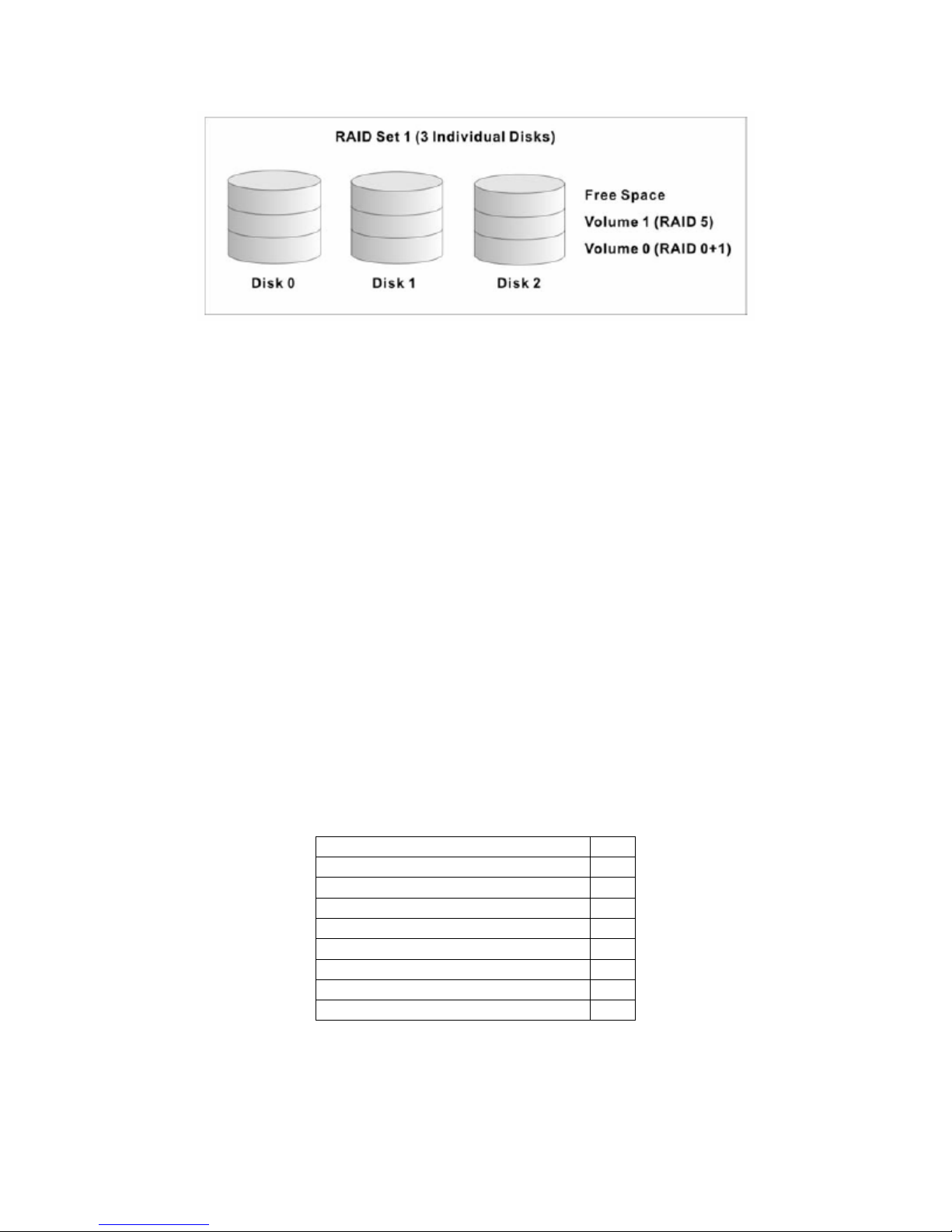
Volume Sets
A Volume Set is seen by the host system as a single logical device. It is organized in a RAID
configuration with one or more physical disks within a RAID set. The RAID configuration will
determine the performance, redundancy, and capacity of the Volume Set. A Volume Set can
consume all or a portion of the disk capacity available in a RAID Set. Multiple Volume Sets can
exist on a group of disks in a RAID Set.
Figure 1-1 below shows a RAID Set with two volumes. Volume 1 is using RAID 5 while Volume
0 uses RAID 0+1 and coexist in the same RAID Set.
8
freeStor Xpand 1500C User’s Manual
Figure 1-1: Volume Sets in a RAID Set
Hot Spare Drives
A hot spare drive is an unused but operational hard drive which is in stand-by mode to replace
an existing disk drive when it fails. In RAID level 1, 0+1, 3, or 5 RAID sets, any unused,
available drive not belonging to a RAID set can defined as a hot spare drive. Hot spares allow
you to replace failed drives automatically without powering down the system. When the RAID
controller detects a drive failure, the system will automatically and transparently rebuild the
RAID using hot spare drives. The RAID set will be reconfigured and rebuilt in the background,
while the RAID controller continues to handle system requests. During the automatic rebuild
process, system activity will continue as normal, however the system performance and fault
tolerance will be negatively impacted.
Note: The hot spare drive must be the same size as or larger than the disk drive
it replaces.
1.5 Unpacking the Unit
Before removing the freeStor Xpand 1500C from the carton, thoroughly inspect the physical
condition of the box. If the packaging is damaged, do not remove any components and contact
your reseller.
If the carton appears to be in good condition, unpack it and check that the freeStor Xpand
1500C and all of the accessories listed below are included and are in good condition.
The freeStor Xpand 1500C includes the following items in the box:
If an item is missing or damaged, contact your reseller for assistance.
9
Item Qty
freeStor Xpand 1500C disk array 1
Drive Canister 15
Ultra320 SCSI Cable 2
Power Cord 2
RS-232 Cable 1
Spare Hard Drive Screws 40
Ultra320 SCSI Terminator 1
User’s Manual CD 1
2 Hardware Installation
2.1 Hardware Components
This section describes the major components of the freeStor Xpand 1500C including its front
panel, LED display panel and rear panel. It is recommended that you read this section before
installing or using the disk array.
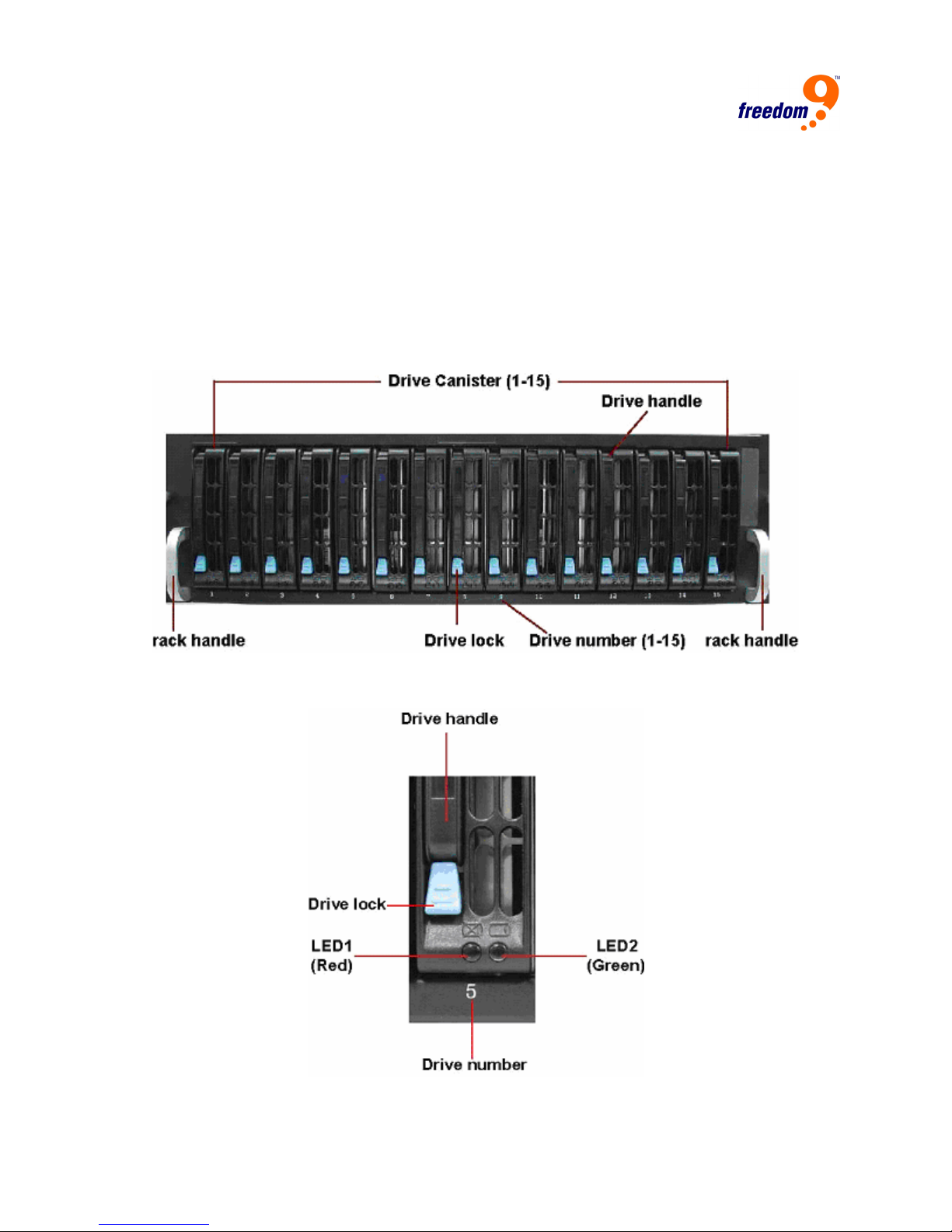
2.1.1 Front Panel
The front panel of the freeStor Xpand 1500C is shown in Figure 1-1.
Figure 2-1: Front Panel
A close-up picture of the drive canister is shown in Figure 1-2.
Figure 2-2: Drive Canister
10
freeStor Xpand 1500C User’s Manual
The descriptions for the components of the drive canister can be found in the table below.
Component Description
Drive handle Locks and secures the drive canister
Drive lock Locks or unlocks the drive canister
Drive number Indicates the number of each canister
LED1 (Red) Indicates the hard drive status
LED2 (Green) Indicate the hard drive status.
The descriptions for the LEDs can be found in the table below.
LED Status Status
LED 1 (Red) flashes continuously No hard drive inserted or hard drive failed
LED 2 (Green) blinks Hard drive is being accessed (read/write)
Both LEDs are neither flashing nor blinking System is in standby mode
Both LEDs flash continuously System is rebuilding
Note: The freeStor Xpand 1500C does not have a power button. When the power
cords are unplugged, you need to wait at least 5 seconds before powering on
unit again. This was designed to prevent the hard drives from being corrupted.
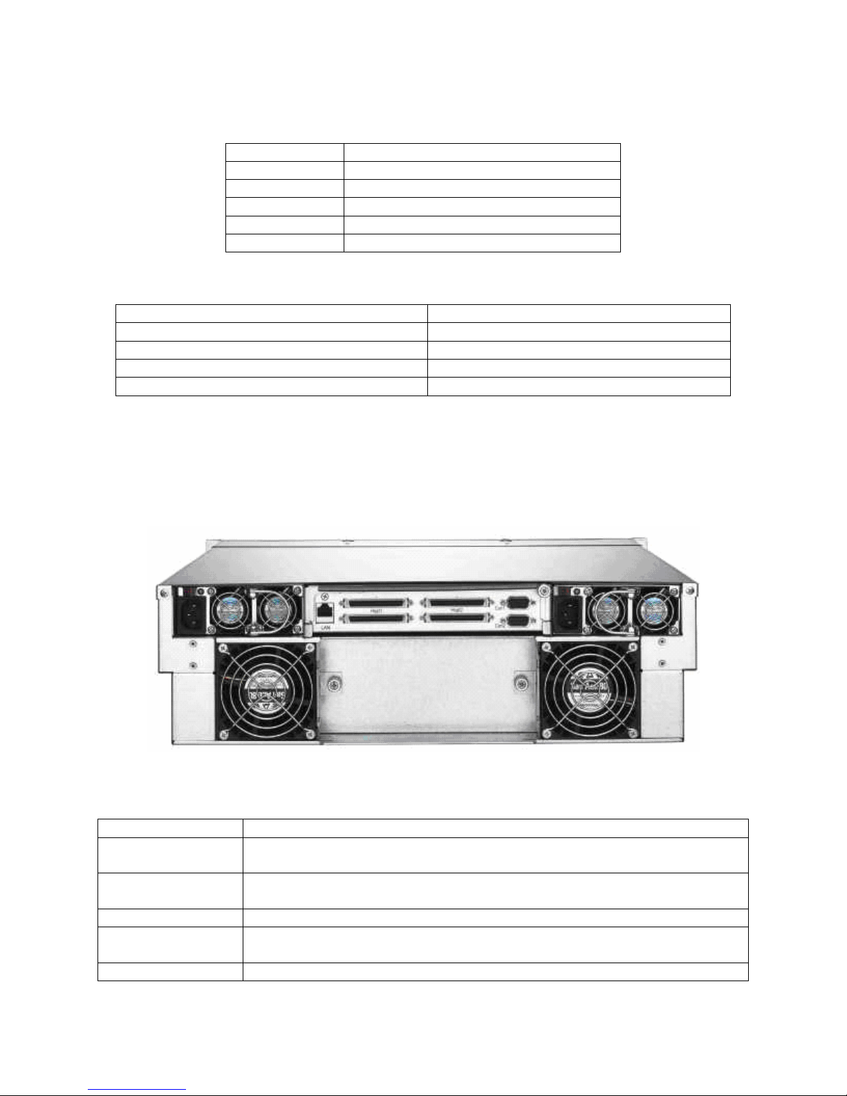
2.1.2 Rear Panel
The rear panel of the freeStor Xpand 1500C is shown in Figure 1-3.
Figure 2-3: Rear Panel
The descriptions of the components of the rear panel can be found in the table below.
Component Description
Con1 Port This RS-232 serial port allows you to connect the unit to a computer and
setup the disk array and monitor the internal environment.
Con2 Port This RS-232 serial port allows you to connect the unit to a computer and
view diagnostic information on the disk array.
LAN Allows the unit to be managed through its web interface.
Host 1 and Host 2 These Ultra320 SCSI ports allow you to connect the disk array to a
server. The unit supports dual SCSI channels.
Fans These hot-swappable fans provide air circulation and reduce the amount
11
of heat within the unit.
Power Supplies These power supplies are redundant and hot-swappable. An alarm will
sound if a power supply fails.
2.2 Hardware Installation
2.2.1 Hard Drive installation
The freeStor Xpand 1500C uses 3.5” serial ATA (SATA) hard drives. To install a hard drive into
the drive canister, follow these steps:
1. Remove the hard drive canister from the chassis.
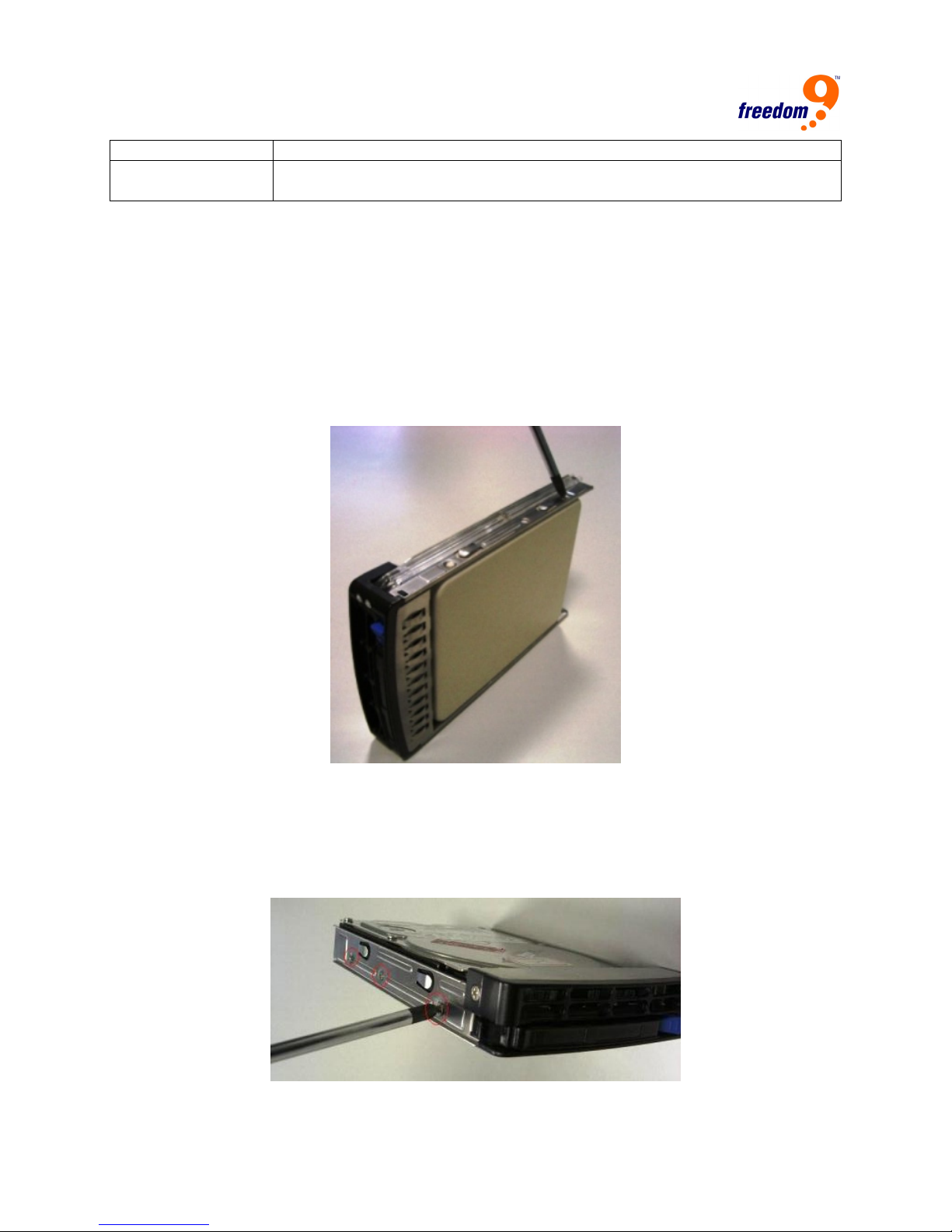
2. Unscrew the placeholder tray from the railings (Figure 2-4). There are two screws on each
side.
Figure 2-4: Drive Canister
3. Place the drive where the placeholder used to be, and screw the hard drive to the railing.
The two screws on both sides need to be fastened tightly. Ensure that the hard drive is
facing the right direction. When the drive is placed with the label side up, the blue latch on
the front should be on the bottom-right corner, and the SATA connector should be on the
back of the drive (Figure 2-5).
Figure 2-5: Installing the Drive
12

freeStor Xpand 1500C User’s Manual
4. Insert the canister with the drive back into the chassis and close the latch to secure it in
place.
5. Repeat steps 1-4 for each drive you are installing. The disk array will automatically detect
which slots are populated once it is powered on.
2.2.2 Terminating the Host Bus
All SCSI buses must be terminated at each end. Termination absorbs electrical signals and
prevents those signals from bouncing back along the bus and causing interference. If you are
not chaining other devices onto the disk array, be sure to connect the terminators included with
the unit to the open SCSI ports.
2.2.3 Computer Connection
The freeStor Xpand 1500C requires an available SCSI port on your computer. If a SCSI host
bus adapter is required for your computer, it must be installed prior to connecting the computer
to the disk array. For optimal performance, the SCSI port should support a 64-bit Ultra320 SCSI
interface. Once the port has been installed, connect the included SCSI cable from the disk
array to the SCSI port on the computer.
2.2.4 Connecting the Power Cord
Before connecting the power cords to the power supplies, make sure the power supplies are
connected firmly to the chassis. To prevent data loss or corruption during a power outage, it is
advised that you connect the disk array to an external uninterruptible power supply (UPS).
2.2.5 Host Bus SCSI ID Assignment
Before using the disk array, you should assign a SCSI ID to the device. The range of SCSI IDs
on a Wide SCSI bus is from 0 to 15. You can do this by using the web interface or a serial
connection (see the next section for details). Be sure to assign an ID that does not conflict with
any other devices on the host bus or the host adapter.
13

3 System Configuration via Terminal Interface
The freeStor Xpand 1500C can be configured using its web interface via Ethernet connection or
its command line interface via serial connection. This section will detail the layout and
commands for the terminal interface, and the next section will detail the layout and commands
of the web interface.
To manage the freeStor Xpand 1500C through the command line interface (CLI), you will need
to connect an RS-232 serial port on your computer to the serial port labeled “Console 1” on the
back of the disk array using the supplied RS-232 cable. Follow these steps to set up a serial
connection to the disk array:
1. Connect the included serial cable from the “Console 1” port on the disk array to a serial port
on your computer.
2. Run a terminal emulation program on your computer, e.g. HyperTerminal for Microsoft
Windows.
3. Connect to the disk array by selecting the proper COM port and using the default terminal
settings shown below.
Baud Rate (bits per second) 115200
Data Bits 8
Parity None
Stop Bits 1
Flow Control None
4. You should see a confirmation that the connection has been setup properly on the screen. If
you do not see anything on the screen, check that you are using ANSI or VTERM emulation,
and press the <tab> key or Ctrl-D to refresh the screen. To navigate in this mode, use the
arrow keys to move the cursor, the <Enter> key to select an option, and the <Esc> key to go
back to the previous menu.
3.1 Operating Modes
The freeStor Xpand 1500C has three operating modes: self-diagnostic mode, operation mode,
and configuration mode. Each of these modes will be discussed below.
Self-Diagnostic Mode
To ensure problem-free operation, the disk array has a built-in self-diagnostic utility. Selfdiagnostics will be performed automatically upon power up of the unit or right after the unit is
restarted. In this mode of operation, all components will be tested.
The Self-Diagnostic mode runs three major diagnostics. The first diagnostic tests the CPU and
supporting core logic chips, internal bus, memory, SCSI controllers, and RS-232 controllers. The
second diagnostic tests the presence of disks on each individual disk channel. It also checks the
functionality of the disks found. The last diagnostic tests the RAID functionality.
Operation Mode
Operation mode continuously reports the operating status of the DAS and the drives connected
to it.
14
freeStor Xpand 1500C User’s Manual
Configuration Mode
Configuration mode is used to modify the settings of disk array. Users can configure the freeStor
Xpand 1500C either through the LAN port or serial port. Note that you are entering configuration
mode whenever you press the “x” key during Operation Mode. Note that you cannot enter
Configuration Mode from both the web and terminal at the same time.
If password protection is enabled, you will be prompted to enter your password before
accessing the system. Unless the disk array is running in Self-Diagnostic Mode, you may select
any of the configuration modes at any time. The Configuration Mode is completely menu-driven
for ease of use, and the menu options allow you to fine-tune the disk array to your specific
requirements.
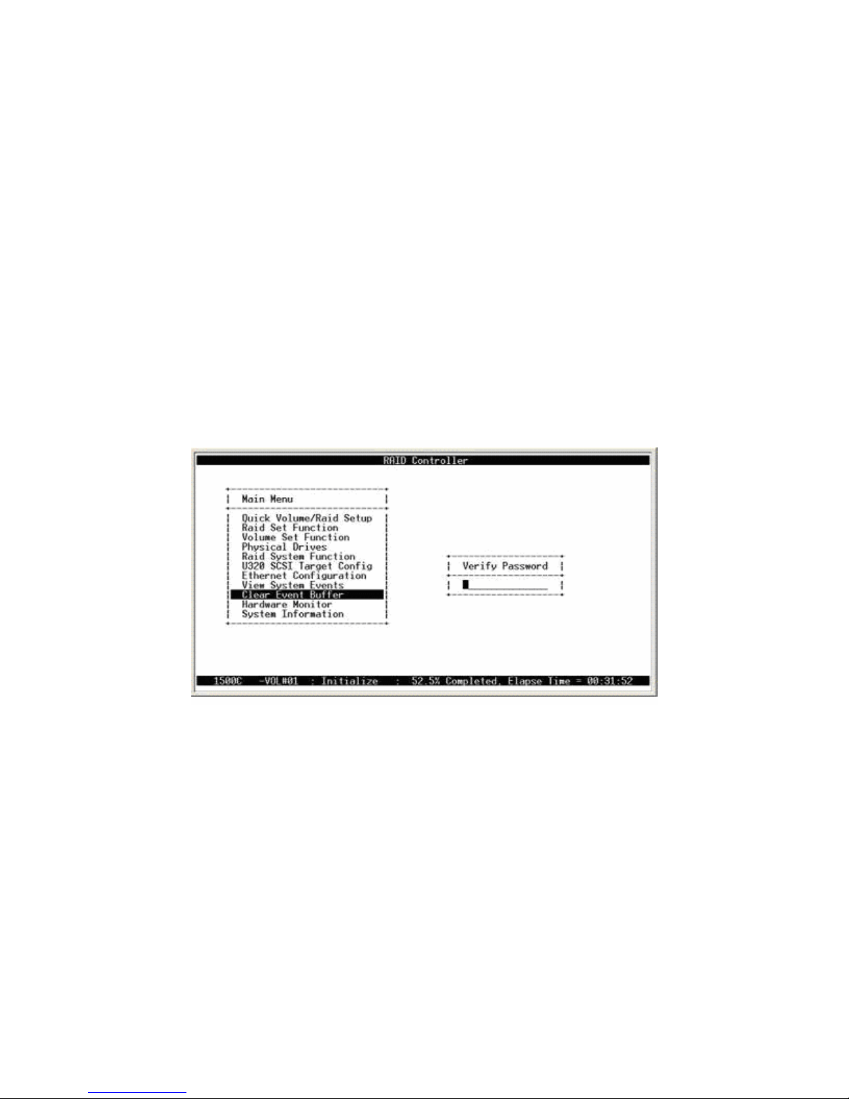
3.2 Main Menu and Password
The main menu consists of the following menus: Quick Volume/RAID Setup, Raid Set Function,
Volume Set Function, Physical Drives, Raid System Function, Ethernet Configuration, View
System Events, Clear Even Buffer, Hardware Monitor and System Information. Figure 3-1
shows the main menu screen when configuring through a terminal. You need to enter a
password for each selection. The default password is 0000.
Menu option descriptions:
Quick Volume/RAID Setup: Create a default configuration based on the number of physical
disk installed.
RAID Set Function: Create a customized raid set.
Volume Set Function: Create a customized volume set.
Physical Drives: View information for each individual disk.
RAID System Function: Set the raid system configuration.
U320 SCSI Target Config: Configures the behavior of the SCSI device on the SCSI bus.
Ethernet Configuration: Configures the Ethernet port for web interface access.
View System Events: Views all system events in the buffer.
Clear Event Buffer: Clears all of the events in the event buffer.
15
Figure 3-1: Terminal Main Menu
Hardware Monitor: Shows the overall system environment status.
System Information: View information about the RAID controller.
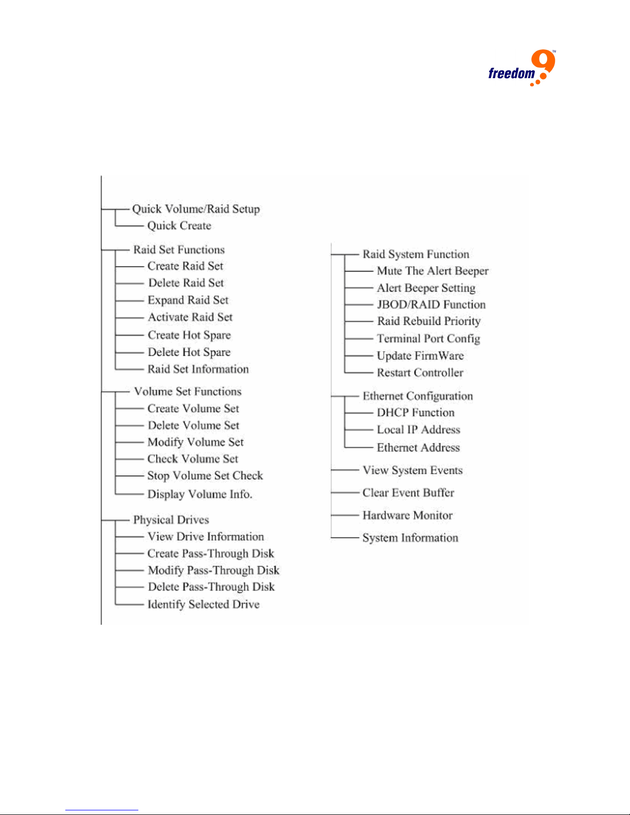
Main Menu Structure
Figure 3-2 shows the hierarchical diagram of the main menu and submenu structure.
3.3 Initial Configuration
You can configure raid sets and volume sets automatically by using the Quick Volume/Raid
Setup feature, or manually by using the Raid Set Function option. First, create hot spares if
desired, then select the method to use for creating the RAID sets and volume sets and follow
the appropriate section below. You only have to follow one of the two configuration methods
located after the Designating Drives as Hot Spares section.
Figure 3-2: Menu Layout
16

freeStor Xpand 1500C User’s Manual
3.3.1 Designating Drives as Hot Spares (optional)
All unused disk drives that are not part of a RAID set can be set to be hot spares. The Quick
Volume/Raid Setup configuration will automatically add a spare disk drive based on the RAID
level selected. First select the “Raid Set Function” option, and then select the “Create Hot
Spare” option to define a hot spare disk drive. To do this, select Create Hot Spare, and a list of
unused drives will be listed. Highlight the desired drive and press <Enter>, then select “Yes”
when prompted.
3.3.2 Using Quick Volume/RAID Setup Configuration
Using the Quick Volume/RAID Setup option allows you to quickly and easily set up a volume
and RAID set. This option automatically creates one RAID set that uses all of the installed disk
drives. The RAID set created is associated with one volume set, and you can select the RAID
type and stripe size of the volume set. Drives designated as Hot Spares will also appear in the
RAID selection. The default settings for the volume set are:
Parameter Setting
Volume Name Volume Set # 00
SCSI Channel/SCSI ID/SCSI LUN 0/0/0
Cache Mode Write-back
Tag Queuing Yes
Max Sync Rate Depends on host adapter setting
The default setting values can be changed after configuration is complete. Follow the steps
below to configure the volume set.
5. Choose “Quick Volume/Raid Setup” from the main menu. The available RAID levels with hot
spares for the current volume set will be displayed.
6. It is recommended that you use drives of the same speed and capacity in an array. If you
use drives with different capacities, all of the drives in the RAID set will be treated as though
they have the capacity of the smallest drive in the RAID set.
The number of physical drives in a specific array determines the RAID types that can be
implemented with the array as follows:
RAID 0 requires one or more physical drives
RAID 1 requires at least 2 physical drives
RAID 1 + Spare requires at least 3 physical drives
RAID 3 requires at least 3 physical drives
RAID 5 requires at least 3 physical drives
RAID 6 requires at least 4 physical drives
RAID 1+0 requires at least 4 physical drives
RAID 3 + Spare requires at least 4 physical drives
RAID 5 + Spare requires at least 4 physical drives
RAID 6 + Spare requires at least 5 physical drives
RAID 1+0 + Spare requires at least 5 physical drives
17

Highlight the RAID level for the volume set and press <Enter>.
7. The capacity for the volume based on the available space on the drives will be displayed.
Press <Enter> to proceed.
8. Use the <up> and <down> arrow keys to select the stripe size for the volume set and press
<Enter>. This parameter specifies the size of the stripes written to each disk when using
RAID 0, 1, 1+0, 5 or 6. You can set the stripe size to 4 KB, 8 KB, 16 KB, 32 KB, 64 KB, or
128 KB. A large stripe size provides better sequential read performance, and a small stripe
size provides better random read performance.
9. Confirm the volume set configuration by pressing selecting “Yes”.
10. When prompted with the “Fast Initialization” prompt, select “Yes” to use Fast Initialization. To
use Normal initialization, select “No”. Normal Initialization takes longer, but operates in the
background so you can use the newly created volume immediately. For Fast Initialization,
the initialization must be completed before the volume set is ready to use.
11. Initialize the volume set that has just been configured.
12. If you need to add additional volume sets, select “Create Volume Set” from the main menu.
3.3.3 Using RAID Set/Volume Set Function
Using the RAID Set and Volume Set options allow you to manually create RAID sets and
volume sets, giving you greater control over the number of drives to use in a RAID set and the
size and number of volume sets to create in each RAID set.
1. Choose “Raid Set Function” from the main menu and press <Enter>.
2. Select “Create Raid Set” and press <Enter>.
3. A “Select SATA Drive For Raid Set” window will be displayed showing the SATA drives
connected to the disk array.
4. Press the “up” and “down” arrow keys to select specific physical drives and press <Enter> to
associate the selected physical drive with the current RAID set.
5. An “Edit The Raid Set Name” dialog box will appear. Enter 1 to 15 alphanumeric characters
to define a unique identifier for the RAID set. The default RAID set name will always appear
as Raid Set #. Press <Enter> to save the name.
6. Select “Yes” to create the RAID set.
7. To create another raid set, repeat from step 2. To begin volume set configuration, go to the
next step.
8. Choose “Volume Set Function” from the main menu and press <Enter>.
9. Select “Create Volume Set” and press <Enter>.
10. It is recommended that you use drives of the same speed and capacity in an array. If you
use drives with different capacities, all of the drives in the RAID set will be treated as though
they have the capacity of the smallest drive in the RAID set.
The number of physical drives in a specific array determines the RAID types that can be
implemented with the array as follows:
RAID 0 requires one or more physical drives
18

freeStor Xpand 1500C User’s Manual
RAID 1 requires at least 2 physical drives
RAID 1 + Spare requires at least 3 physical drives
RAID 3 requires at least 3 physical drives
RAID 5 requires at least 3 physical drives
RAID 6 requires at least 4 physical drives
RAID 1+0 requires at least 4 physical drives
RAID 3 + Spare requires at least 4 physical drives
RAID 5 + Spare requires at least 4 physical drives
RAID 6 + Spare requires at least 5 physical drives
RAID 1+0 + Spare requires at least 5 physical drives
Highlight the RAID level for the volume set and press <Enter>.
11. Select a RAID set from the “Create Volume From Raid” Set window and press <Enter>.
12. The Volume Creation screen shows the default values for the volume set that is currently
being configured. Use the arrow keys and <Enter> key to select and change the values to
the desired settings, and press <Esc> after the changes have been made to enter the
Initialization selection screen.
13. When prompted with the “Fast Initialization” prompt, select “Yes” to use Fast Initialization. To
use Normal initialization, select “No”. Normal Initialization takes longer, but operates in the
background so you can use the newly created volume immediately. For Fast Initialization,
the initialization must be completed before the volume set is ready to use.
14. If space remains in the RAID set, the next volume set can be configured. Repeat steps 9 to
13 to configure another volume set.
Note: You can use this method to view existing RAID sets and Volume sets, and
make any modifications to them or delete them as desired. In the volume set
section, you can use the “Modify Volume Set” function to modify all volume set
parameters except the capacity size.
3.4 Quick Volume/Raid Setup
The Quick Volume/Raid Setup allows you to create a RAID set and volume set quickly and
easily. For detailed instructions on how to use this feature, see section 3.3.2.
3.5 RAID Set Function
The RAID Set Function option (Figure 3-3) allows you to create, edit, and delete RAID Sets and
Hot Spare drives.
19
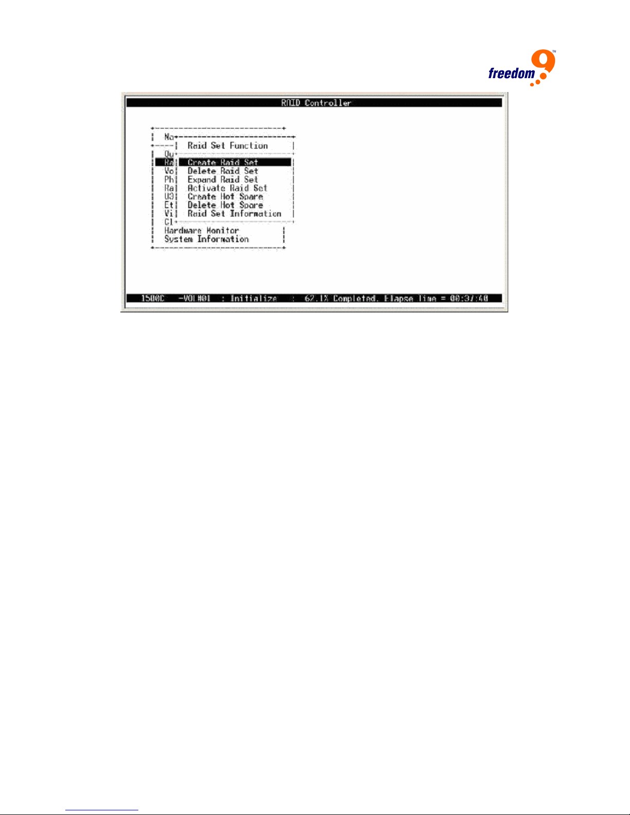
Figure 3-3: RAID Set Function Menu
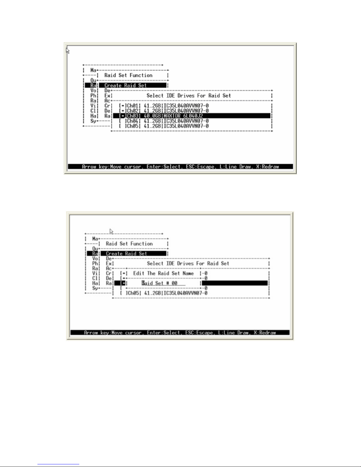
3.5.1 Create Raid Set
To create a RAID set, follow the procedure below:
15. Select “Raid Set Function” from the main menu.
16. Select “Create Raid Set”.
17. A “Select SATA Drive For Raid Set” window (Figure 3-4) will displayed showing the SATA
drives connected to the current controller. Press the “up” and “down” arrow keys to highlight
the a drive and then press <Enter> to add to it to the RAID set. Repeat for each drive to add
to the RAID set.
Once you have selected all of the drives for the RAID set, press <Esc>. A confirmation
screen will appear, select “Yes” to confirm.
20
freeStor Xpand 1500C User’s Manual
Figure 3-4: Create RAID Set
18. An “Edit The Raid Set Name” dialog box will appear (Figure 3-5). Enter 1 to 15 alphanumeric
characters to define a unique identifier for the RAID set. The default RAID set name will
appear as Raid Set #.
Figure 3-5: Edit RAID Set Name
3.5.2 Delete RAID Set
To change a RAID set, you need to first delete it and then recreate it. To delete a RAID set,
select the RAID set you wish to delete in the “Select Raid Set to Delete” screen (Figure 3-6) and
press <Enter>. Select “Yes” in the confirmation box to confirm the deletion. Another confirmation
screen will appear for security purposes, select “Yes” in this window to finalize the deletion.
21
 Loading...