

Freedom9 Capture 1000, Capture 750, Capture 2000, freeGuard Capture User Manual

freeGuard Capture
Internet Content Recorder and
Email Archiver
USER’S MANUAL
Part#:
ICR 1000
ICR 2000
Rev 2.0

Copyright and Trademark Information
This document contains proprietary information that is protected by copyright. All
rights reserved. No part of this document may be photocopied, reproduced, or
translated into another language without prior expressed written consent from
Freedom9 Inc.
© Copyright 2008, the freedom9 company logo are trademarks or registered
trademarks of Freedom9 Inc. All rights reserved. Windows is a trademark or
registered trademark of Microsoft Corporation. Other trademarks or registered
trademarks are the property of their respective holders.

FCC Warning
This equipment has been tested and found to comply with the regulations for a
Class A digital device, pursuant to Part 15 of the FCC Rules. These limits are
designed to provide reasonable protection against harmful interference when the
equipment is operated in a commercial environment. This equipment generates,
uses, and can radiate radio frequency energy and, if not installed and used in
accordance with this user’s guide, may cause harmful interference to radio
communications. Operation of this equipment in a residential area is likely to cause
harmful interference, in which case the user will be required to correct the
interference at his/her own expense.
CE Mark Warning
This is a Class A product. In a domestic environment, this product may cause radio
interference, in which case the user may be required to take adequate measures.
VCCI Warning
This is a product of VCCI Class A Compliance.
UL Warning
a) Elevated Operating Ambient Temperature- If installed in a closed or multi-unit
rack assembly, the operating ambient temperature of the rack environment may be
greater than room ambient. Therefore, consideration should be given to installing
the equipment in an environment compatible with the manufacturer's maximum
rated ambient temperature (Tmra).
b) Reduced Air Flow- Installation of the equipment in a rack should be such that
the amount of air flow required for safe operation of the equipment is not
compromised.
c) Mechanical Loading- mounting of the equipment in the rack should be such that
a hazardous condition is not achieved due to uneven mechanical loading.
d) Circuit Overloading- Consideration should be given to the connection of the
equipment to the supply circuit and the effect that overloading of circuits might
have on over current protection and supply wiring. Appropriate consideration of
equipment nameplate ratings should be used when addressing this concern.
e) Reliable Earthing - Reliable earthing of rack-mounted equipment should be
maintained. Particular attention should be given to supply connections other than
direct connections to the branch circuit (e.g., use of power strips).


freeGuard Capture Appliance User’s Manual
TABLE OF CONTENTS
1 PRODUCT OVERVIEW ....................................................................................................................9
INTRODUCTION...........................................................................................................................9
FEATURE HIGHLIGHTS...............................................................................................................9
2 QUICK INSTALLATION..................................................................................................................10
APPLIANCE FRONT PANEL ......................................................................................................10
Front panel for ICR 1000 ................................................................................. 10
Front Panel for ICR2000 .................................................................................. 11
SYSTEM DEPLOYMENT............................................................................................................12
Bridge Mode................................................................................................... 12
Sniffer Mode .................................................................................................. 13
ADMINISTRATION LOGIN..........................................................................................................14
SETUP WIZARD .........................................................................................................................16
SYSTEM CLOCK SYNCHRONIZATION.....................................................................................20
USER GROUPS MANAGEMENT...............................................................................................21
3 SYSTEM .........................................................................................................................................22
INTERFACE OVERVIEW............................................................................................................22
ADMINISTRATOR ACCOUNTS..................................................................................................24
Admin Account ............................................................................................... 24
Read/Write Privileges ...................................................................................... 24
Group Administrator........................................................................................ 24
INTERFACE IP............................................................................................................................26
Setup Interface IP Address............................................................................... 26
SYSTEM / SETTING...................................................................................................................27
System setting overview.................................................................................. 27
Backup / Restore Configuration Settings ............................................................ 28
HTTP and HTTPS Communication Ports .............................................................. 28
Log Storage Time ........................................................................................... 28
Reboot the System ......................................................................................... 28
DATE / TIME ...............................................................................................................................30
Synchronize system clock ................................................................................ 30
Daylight saving time (Summer Time)................................................................. 30
PERMITTED IP ADDRESSES ....................................................................................................31
LANGUAGE ................................................................................................................................32
WIZARD ......................................................................................................................................32
1

LOG OUT ....................................................................................................................................32
Software Update............................................................................................. 33
4 USER LIST .....................................................................................................................................35
SETTING.....................................................................................................................................35
Setting – Upload User List................................................................................ 36
LOGGED USER LIST .................................................................................................................37
Logged User List – modify a user ...................................................................... 38
Logged User List – Search................................................................................ 39
Logged User List – Add new subnet to the group ................................................. 40
Logged User List – Dept/Group View.................................................................. 41
IGNORED USER LIST................................................................................................................42
5 INSTANT MESSAGING MANAGEMENT.......................................................................................43
CONFIGURE...............................................................................................................................43
Login Notice................................................................................................... 43
Login Notice - Examples .................................................................................. 44
AUTHENTICATION.....................................................................................................................47
Setting.......................................................................................................... 47
User ............................................................................................................. 47
RADIUS......................................................................................................... 48
POP3 ............................................................................................................ 48
LDAP ............................................................................................................ 48
RULES ........................................................................................................................................49
Default Rule................................................................................................... 49
Account Rule.................................................................................................. 51
6 P2P MANAGEMENT ......................................................................................................................52
DEFAULT RULE..........................................................................................................................52
USER RULE................................................................................................................................53
7 RECORD.........................................................................................................................................55
SETTING.....................................................................................................................................55
Signature Pattern Update (Web Mail, IM, P2P) .................................................... 56
User Name Binding ......................................................................................... 56
LAN to LAN Recording ..................................................................................... 57
The maximum entries to be displayed................................................................ 57
Default Character Encoding .............................................................................. 57
HTTP cache setting ......................................................................................... 58
RECORD - USER .......................................................................................................................59
2

freeGuard Capture Appliance User’s Manual
RECORDED SERVICE...............................................................................................................61
SMTP Messages .............................................................................................. 61
POP3/IMAP Messages ...................................................................................... 64
HTTP Records................................................................................................. 65
IM – Instant Messaging ................................................................................... 66
Web SMTP Messages ....................................................................................... 67
Web POP3 Messages ....................................................................................... 68
Record – FTP Sessions..................................................................................... 69
Record – Telnet Sessions ................................................................................. 70
8 FLOW ANALYSIS ...........................................................................................................................71
OVERVIEW.................................................................................................................................71
TODAY TOP-10...........................................................................................................................72
HISTORY TOP-N ........................................................................................................................74
Flow Statistics ................................................................................................ 76
9 ANOMALY FLOW IP ......................................................................................................................77
OVERVIEW.................................................................................................................................77
ANOMALY FLOW IP SETTING...................................................................................................78
VIRUS INFECTED IP..................................................................................................................79
INTRUSION IP..........................................................................................................................80
10 LOCAL DISK ..................................................................................................................................81
STORAGE TIME .........................................................................................................................81
DISK SPACE ...............................................................................................................................83
11 REMOTE BACKUP ........................................................................................................................86
SETTINGS ..................................................................................................................................87
Backup Settings ............................................................................................. 87
Browse Settings ............................................................................................. 88
Browse.......................................................................................................... 89
12 REPORT .........................................................................................................................................90
SETTING.....................................................................................................................................90
Settings – Scheduled Report / Periodic............................................................... 90
Settings - History Report ................................................................................. 94
STORAGE REPORT...................................................................................................................97
13 SYSTEM STATUS...........................................................................................................................99
SYSTEM INFO............................................................................................................................99
CURRENT SESSION................................................................................................................101
3

EVENT LOG..............................................................................................................................102
14 TECHNICAL SUPPORT ...............................................................................................................103
Online Support ..............................................................................................103
Telephone Support.........................................................................................103
4

freeGuard Capture Appliance User’s Manual
Index of Figures
Figure 1, ICR1000 Front Panel ........................................................................................ 10
Figure 2, ICR2000 Front Panel ........................................................................................ 11
Figure 3, Deployment - Bridge Mode................................................................................ 12
Figure 4, Deployment - Sniffer Mode................................................................................ 13
Figure 5, Administration Login ........................................................................................ 14
Figure 6, Answer Yes to security alert for HTTPS on Web interface ....................................... 14
Figure 7, Setup Wizard .................................................................................................. 16
Figure 8, Choose default HTML character encoding method ................................................. 16
Figure 9, Choose name binding method............................................................................ 16
Figure 10, Enter the settings in interface address .............................................................. 17
Figure 11, Enter the subnet to capture............................................................................. 18
Figure 12, System clock synchronization .......................................................................... 20
Figure 13, Set the name of department or group ............................................................... 21
Figure 14, User List / Logged.......................................................................................... 21
Figure 15, Menu – System.............................................................................................. 22
Figure 16, Create a Group Administrator – 1..................................................................... 25
Figure 17, Create a Group Administrator – 2..................................................................... 25
Figure 18, Interface IP address setup............................................................................... 26
Figure 19, System setting page....................................................................................... 27
Figure 20, Save the configuration file............................................................................... 28
Figure 21, Reboot confirmation ....................................................................................... 29
Figure 22, System date/time setting................................................................................ 30
Figure 23, Add a new Permitted IP Address....................................................................... 31
Figure 24, Permitted IP address list ................................................................................. 31
Figure 25, Log out confirmation ...................................................................................... 32
Figure 26, Firmware update............................................................................................ 33
Figure 27, Update firmware – browse to find the file .......................................................... 33
Figure 28, User List menu .............................................................................................. 35
Figure 29, User List - Settings......................................................................................... 35
Figure 30, Save / export user groups to file ...................................................................... 36
Figure 31, User list in subnet view................................................................................... 37
Figure 32, User Name Details ......................................................................................... 37
Figure 33, Modify a user - 1............................................................................................ 38
Figure 34, Modify a user - 2............................................................................................ 38
Figure 35, Search for a user ........................................................................................... 39
Figure 36, Search for a user – search box......................................................................... 39
Figure 37, Search for a user - result ................................................................................ 39
Figure 38, Add a new subnet to the user group ................................................................. 40
Figure 39, Add a new subnet – Example........................................................................... 40
Figure 40, User List - Group View .................................................................................... 41
Figure 41, Confirm to ignore a user ................................................................................. 41
Figure 42, Ignored user list ............................................................................................ 42
Figure 43, Move Ignored user to Logged........................................................................... 42
5

Figure 44, IM Management menu (expended) ................................................................... 43
Figure 45, IM Login Notice - configuration ........................................................................ 44
Figure 46, IM Login Notice – MSN Example ....................................................................... 45
Figure 47, IM notice - NetBIOS example........................................................................... 45
Figure 48, IM notice – ICQ ............................................................................................. 46
Figure 49, IM Authentication Messages ............................................................................ 47
Figure 50, IM Authentication - Default Rules ..................................................................... 49
Figure 51, IM Authentication - Account Rules .................................................................... 51
Figure 52, P2P Management - Default Rule ....................................................................... 52
Figure 53, P2P Management - User Rule........................................................................... 53
Figure 54, General settings of capturing ........................................................................... 55
Figure 55, Example of the Record / Setting page ............................................................... 55
Figure 56, Default Character Encoding ............................................................................. 57
Figure 57, Captured data by user .................................................................................... 59
Figure 58, Customer view search by user ......................................................................... 60
Figure 59, Record / Service ............................................................................................ 61
Figure 60, Records Captured - SMTP................................................................................ 61
Figure 61, Records Captured - Forward ............................................................................ 62
Figure 62, Records Captured - SMTP Search ..................................................................... 62
Figure 63, Download the search result ............................................................................. 63
Figure 64, Records Captured - POP3/IMAP........................................................................ 64
Figure 65, Records Captured - HTTP ................................................................................ 65
Figure 66, Records Captured - IM.................................................................................... 66
Figure 67, Records Captured - Web SMTP......................................................................... 67
Figure 68, Records Captured - Web POP3 ......................................................................... 68
Figure 69, Records Captured – FTP.................................................................................. 69
Figure 70, Records Captured - FTP, download a copy ......................................................... 69
Figure 71, Records Captured – Telnet Sessions ................................................................. 70
Figure 72, Telnet Session Details..................................................................................... 70
Figure 73, Flow Analysis - Menu ...................................................................................... 71
Figure 74, Flow Analysis - Today Top 10........................................................................... 72
Figure 75, Flow Analysis - Top N ..................................................................................... 74
Figure 76, Flow Analysis - Statistics Chart ........................................................................ 76
Figure 77, Anomaly flow IP menu .................................................................................... 77
Figure 78, Anomaly flow detect - general settings.............................................................. 78
Figure 79, Virus-infected IP ............................................................................................ 79
Figure 80, NetBIOS Notification Shown to the Victim User................................................... 79
Figure 81, Virus-infected IP Email alerts........................................................................... 79
Figure 82, Example of Intrusion IP detection..................................................................... 80
Figure 83, Local Disk Menu............................................................................................. 81
Figure 84, Storage Time ................................................................................................ 82
Figure 85, Disk Space Usage .......................................................................................... 84
Figure 86, Disk Space Usage Report ................................................................................ 84
Figure 87, Disk space usage details (continued) ................................................................ 85
6

freeGuard Capture Appliance User’s Manual
Figure 88, Remote Backup menu..................................................................................... 86
Figure 89, Remote Backup - Backup Settings .................................................................... 87
Figure 90, Remote Backup - Browse Settings .................................................................... 88
Figure 91, Remote Backup – Browse POP3/IMAP ............................................................... 89
Figure 92, Report Settings.............................................................................................. 90
Figure 93, Daily report sent by the email.......................................................................... 91
Figure 94, Sample Report by Email – Network Traffic ......................................................... 92
Figure 95, Daily Report by Users (partial)......................................................................... 94
Figure 96, Report Sample - Weekly Report ....................................................................... 95
Figure 97, Report Sample - Weekly Traffic........................................................................ 96
Figure 98, System Status............................................................................................... 99
Figure 99, System Status - Current Session.....................................................................101
Figure 100, System Status - Current Session Search.........................................................101
Figure 101, Status - Event Log.......................................................................................102
7

8

freeGuard Capture Appliance User’s Manual
1 Product Overview
Introduction
Thank you for purchasing the freeGuard Capture appliance, the Internet Content Recorder
and Email Archiver.
The freeGuard Capture appliance allows organizations to capture, track and report on
Internet activities, such as: browsed web pages, web mail, SMTP/POP3 and IMAP mail,
Instant Messaging applications (MSN, Yahoo messenger, ICQ, AIM), FTP and Telnet.
The freeGuard Capture appliance can work as a powerful Email archiver and an instant
messaging archiver.
The freeGuard Capture appliance provides valuable information about internal Internet
usage and surfing patterns to Network Administrators and employee supervisors. With the
reporting and management tools, it can quick and easy to limit the access to certain
services, and by monitoring employee activity, organizations can quickly improve their
productivity.
Feature highlights
Key features:
z Supports Sniffing and Bridge modes
z Will capture a record of HTTP, SMTP, POP3, IMAP, IM, Web mail, FTP and Telnet
contents
z Supports remote backup to maintain historical data as far back as needed
z Multi permission levels for group administrators, up to 36 groups on ICR2000, 12
groups on ICR appliance
z Instant alarm when a potential virus is detected
z Detailed and graphical reporting with user names binded to IP or MAC addresses
z Supports remote monitoring
z LAN to LAN recording for internal mail servers (such as Exchange, Groupwise*, etc)
z Use IM/P2P management to block Internet content (Bridge Mode)
z Easy-to-use Web Interface
z User based bandwidth usage analysis **
z Unlimited users
* Some mail server configurations may be required.
** Only available on certain models
9
2 Quick Installation
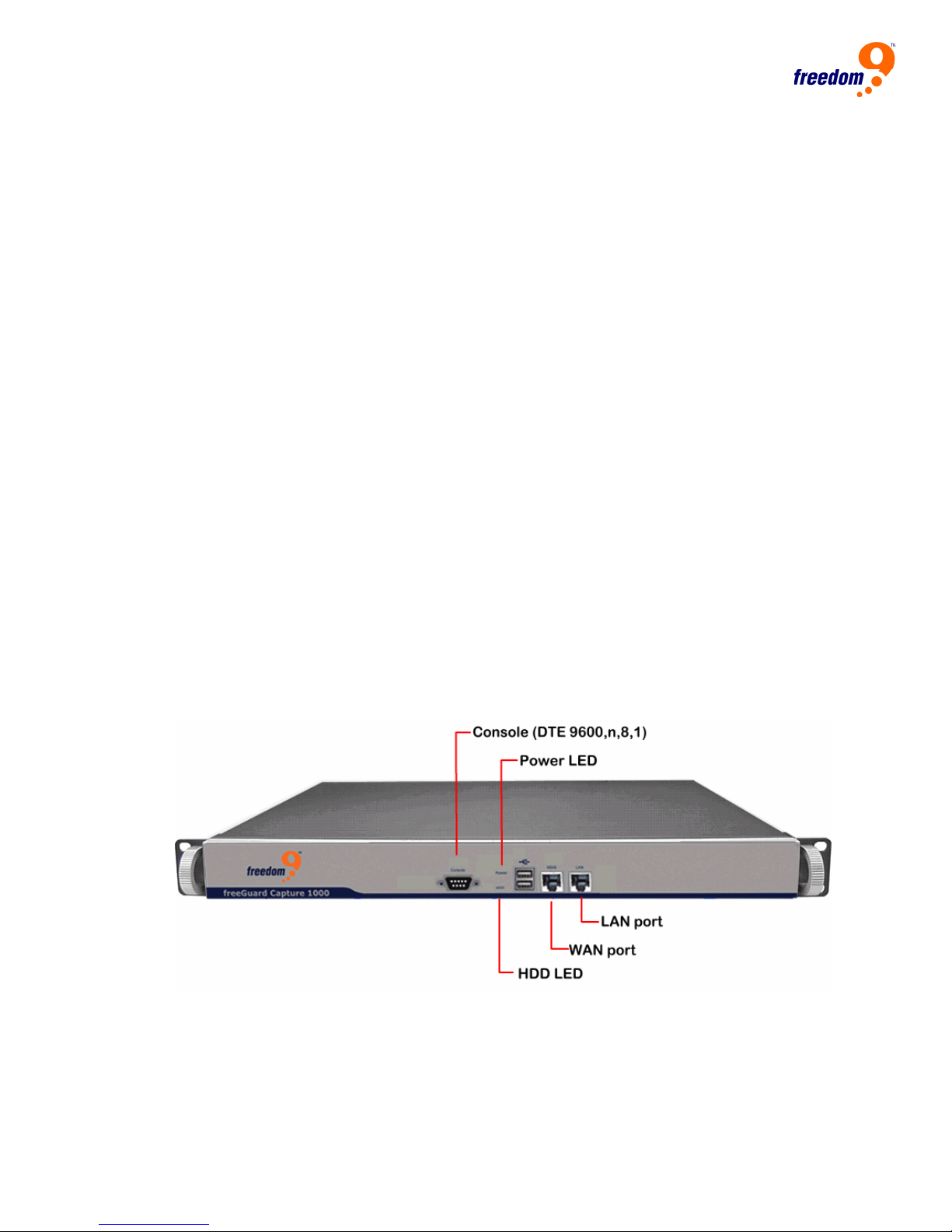
Appliance front panel
Interfaces and layout for the ICR appliance are listed below,
z Power Led
Green: the appliance is powered on.
z Hard Disk LED
Flashing: System is accessing data from the hard drive.
z Console Port
One DB9 console port for serial cable connection.
z WAN/LAN ports
RJ-45 ports allow you to connect to your WAN and/or LAN.
Front panel for ICR 1000
Figure 1, ICR1000 Front Panel
10
freeGuard Capture Appliance User’s Manual
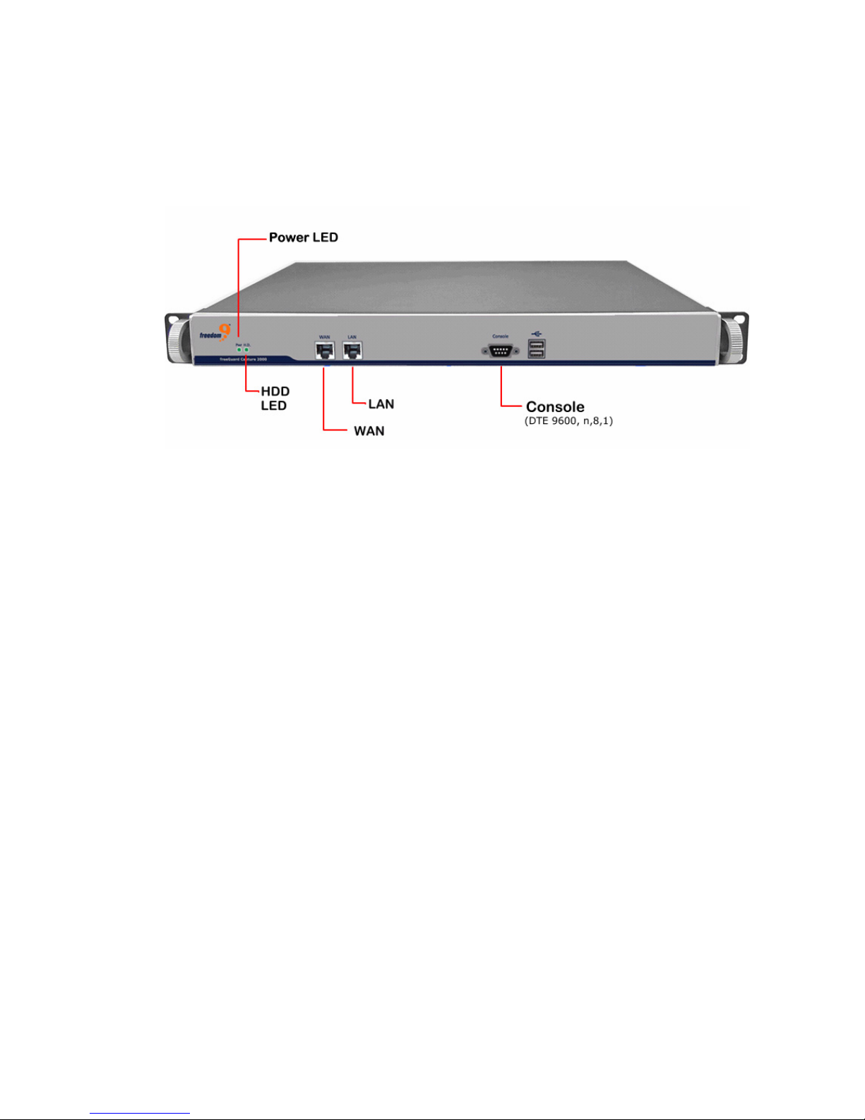
Front Panel for ICR2000
Figure 2, ICR2000 Front Panel
11

System Deployment
There are two ways for ICR appliance deployment: Bridge mode or Sniffer mode.
Before you connect the ICR appliance into your live network, you may want to
configure it according to your network topology and requirement.
Please note, each ICR appliance from Freedom9 Inc has been pre-configured with IP address
and one administration account. The default IP address for the ICR appliance is 192.168.1.1
with subnet mask set to 255.255.255.0, please make necessary changes to avoid IP conflict in
your network.
Bridge Mode
Connect the WAN port on the ICR appliance to firewall or gateway in our network, and the
LAN port to the internal network via hub or switch.
Figure 3, Deployment - Bridge Mode
12
freeGuard Capture Appliance User’s Manual
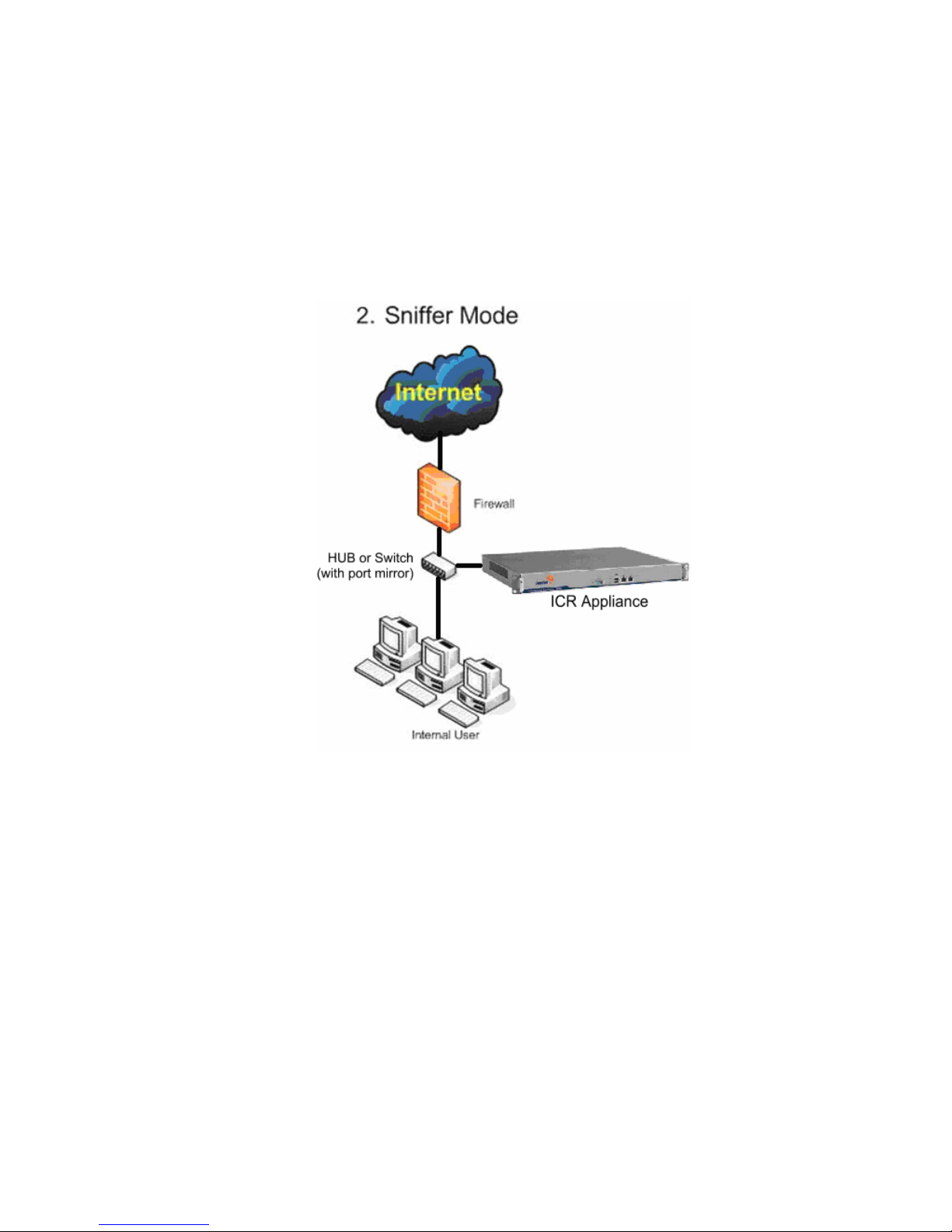
Sniffer Mode
Link one of the internet recorder’s port to the mirror port of core switch or any port of the
hub.
Figure 4, Deployment - Sniffer Mode
13
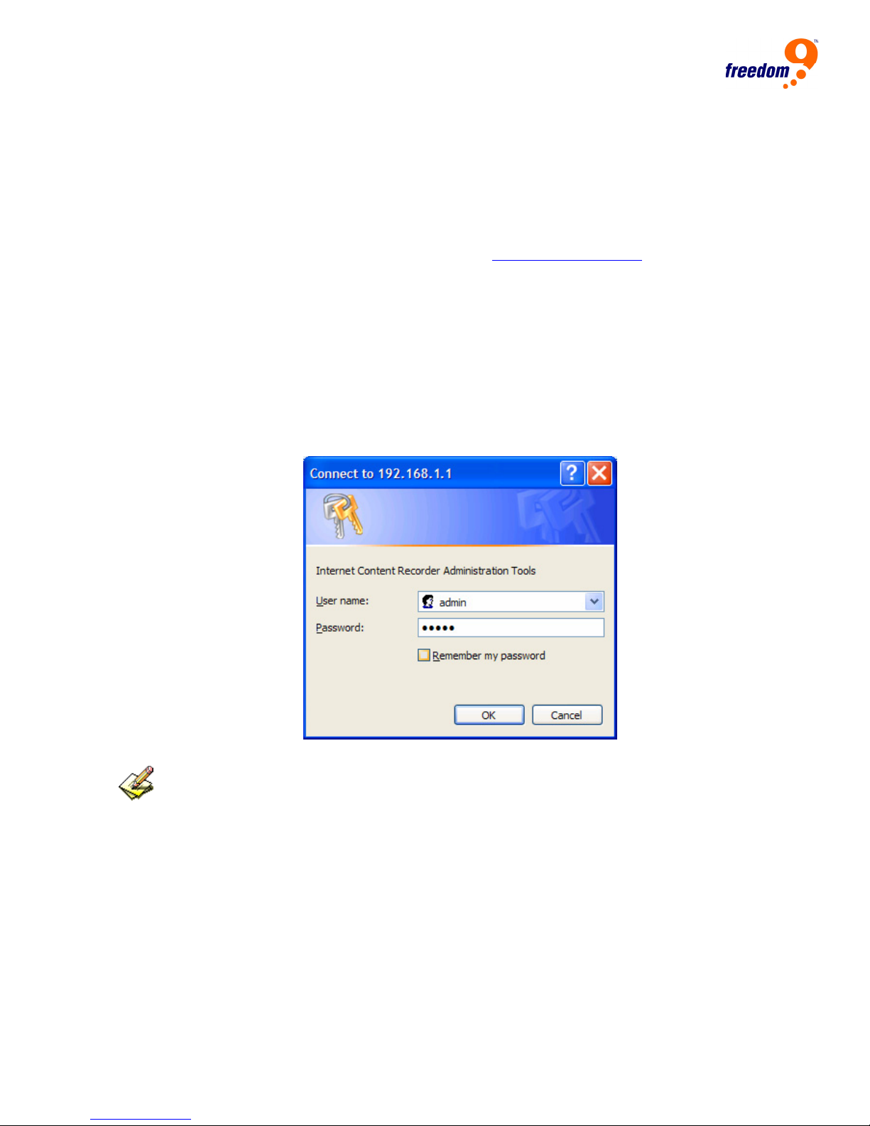
Administration Login
Connecting the administration PC and ICR Appliance’s LAN port to the same Hub or Switch,
make sure the administration PC is in the same network segment as the ICR appliance.
The default IP address for ICR appliance is 192.168.1.1 with subnet mask 255.255.255.0.
Start the web browser IE or Netscape, browse to http://
Once you see the pop up login dialogue box, type in the correct User Name and
Password to login.
If it’s the first time of login, please use the default login:
z User name: admin
z Password: admin
Figure 5, Administration Login
192.168.1.1.
If you are using HTTPS to access the Web interface of ICR appliance, please click “Yes”
when you see the security alert dialogue box pops up.
Figure 6, Answer Yes to security alert for HTTPS on Web interface
14

freeGuard Capture Appliance User’s Manual
15
Setup Wizard
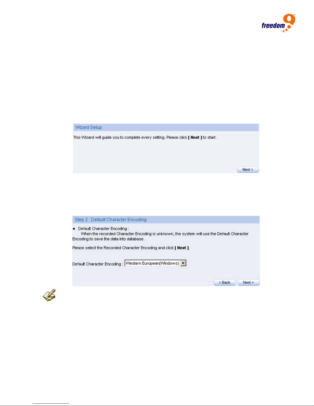
If it’s the first time that user log into the system, the Setup Wizard page will be displayed
automatically.
Setup Wizard will guide you through the basic configurations for the ICR appliance, please
follow the instructions on each page.
This page can also be found under System Æ Setup Wizard.
Figure 7, Setup Wizard
Setup Wizard will help you on the configurations on:
Choose display language for the Web interface
Choose the default HTML Character Encoding method
Figure 8, Choose default HTML character encoding method
For unknown character encoding from the contents captured, the “Default Character
Encoding” will be used for display and storage.
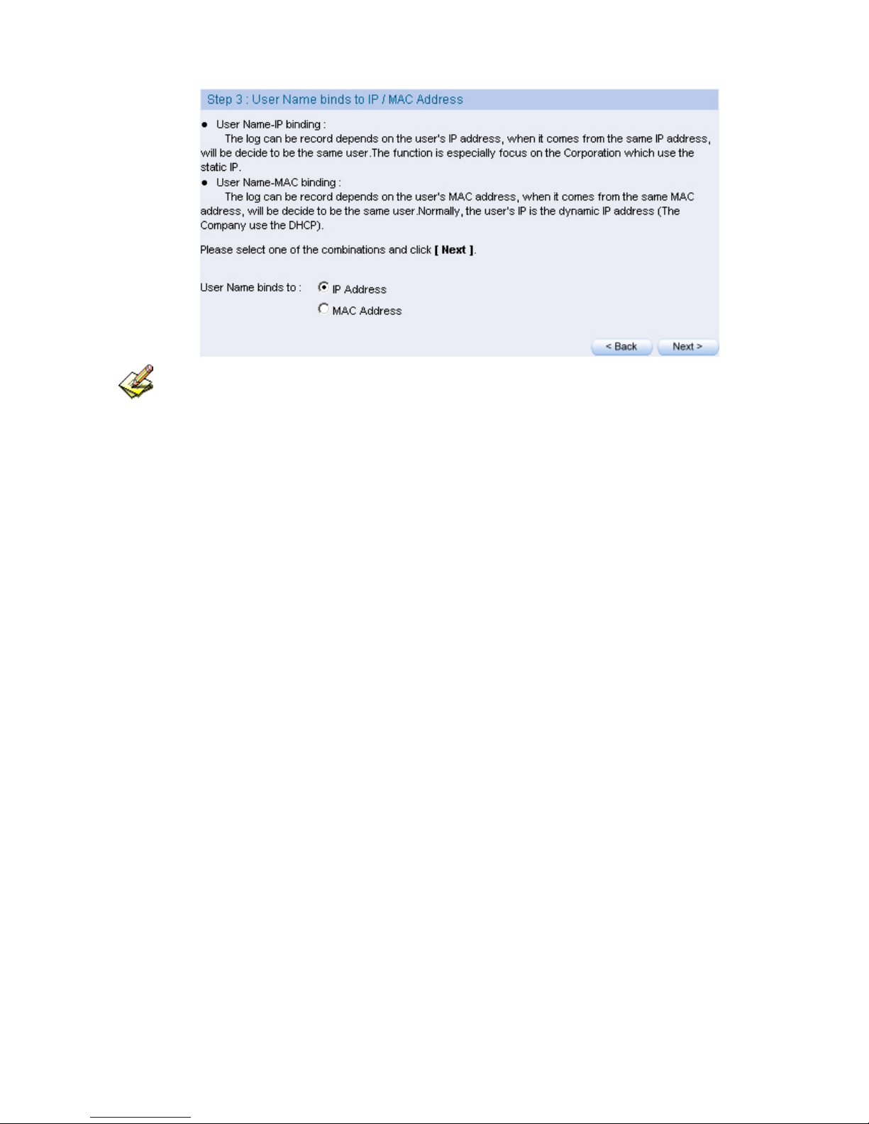
z Choose the way of user name bindings. User names can be either binds to IP
address or binds to MAC Address
Figure 9, Choose name binding method
16
freeGuard Capture Appliance User’s Manual
Name Binding:
- Binding to IP addresses: When the system captures the network traffic, all the network packets
from one IP address, will be treated as the one user. This method is usually used for the
corporation with the static IP addresses implemented in their network.
- Binding to MAC addresses: When the system captures the network traffic, all the packets from the
one MAC address, will be treated as one user. This method is generally used in the network
that clients PC does not have a unique IP address, such as a network with DHCP implemented.
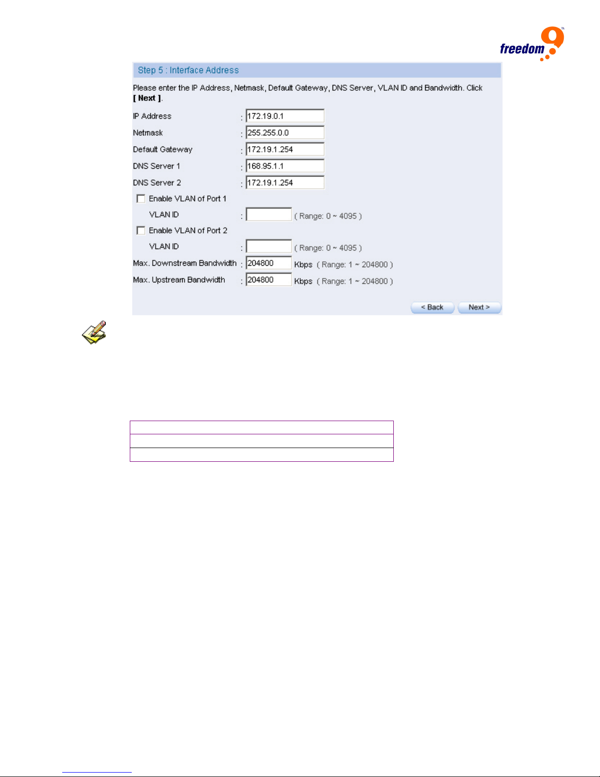
Setup Interface IP Address
If different IP addresses range has been used other than the default IP address of ICR
appliance, you can also setup in this page.
– Enter the valid IP for your internal network. A valid value for subnet mask,
default gateway and DNS server address are also required.
– If VLAN has been implemented in your network, you may want to enable the
VLAN for WAN port (port 1) and LAN port (port 2).
– Limitation to bandwidth of Downstream and Upstream can also be set.
Figure 10, Enter the settings in interface address
17
The management interface address must correspond to the company’s environment.
Set the IP in same subnet as LAN. If the LAN is not the segment of 192.168.1.x, for example,
the LAN is the segment of 172.16.x.x, then the interface IP needs to be changed to 172.16.x.x.
For your reference, you may configure your management address based on the subnet ranges
below:
10.0.0.0 ~ 10.255.255.255
172.16.0.0 ~ 172.31.255.255
192.168.0.0 ~ 192.168.255.255
Enter all the subnet information to be captured, and click Finish
You can have the ICR appliance to capture different subnet from your network at the same time,
also you can assign the name to the subnet, which is treated as a department or user group in ICR
appliance.
Figure 11, Enter the subnet to capture
18

freeGuard Capture Appliance User’s Manual
If the interface IP has been changed in previous steps, and the Finish button was clicked, you’ll
need to use the new IP address for your web browser, in order to log in again.
19
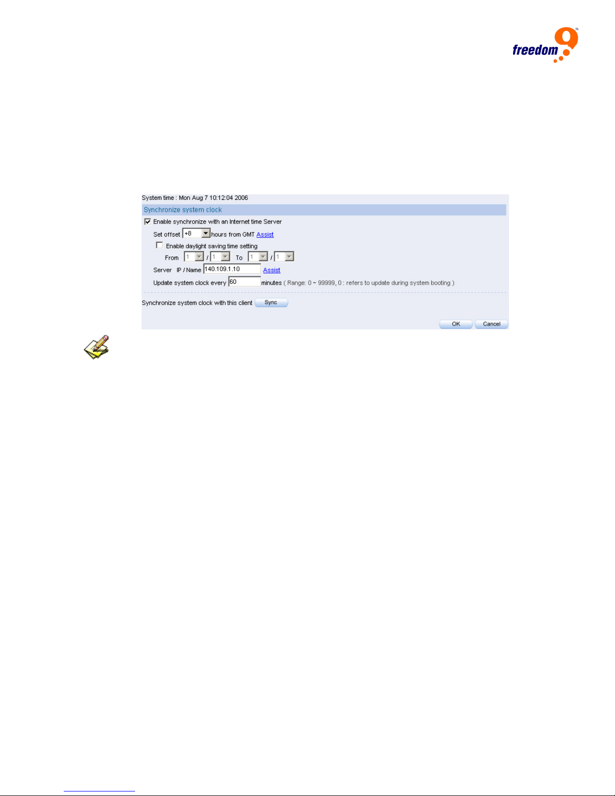
System Clock Synchronization
Under SystemÆDate/Time, select Enable synchronize with an internet time
Server (Please adjust the time lag depends on the time area) or click Synchronize
system clock with this client , in order to provide the current time for the system.
Figure 12, System clock synchronization
If the local area has the daylight saving time restriction, then select Enable daylight saving time
setting.
20
freeGuard Capture Appliance User’s Manual
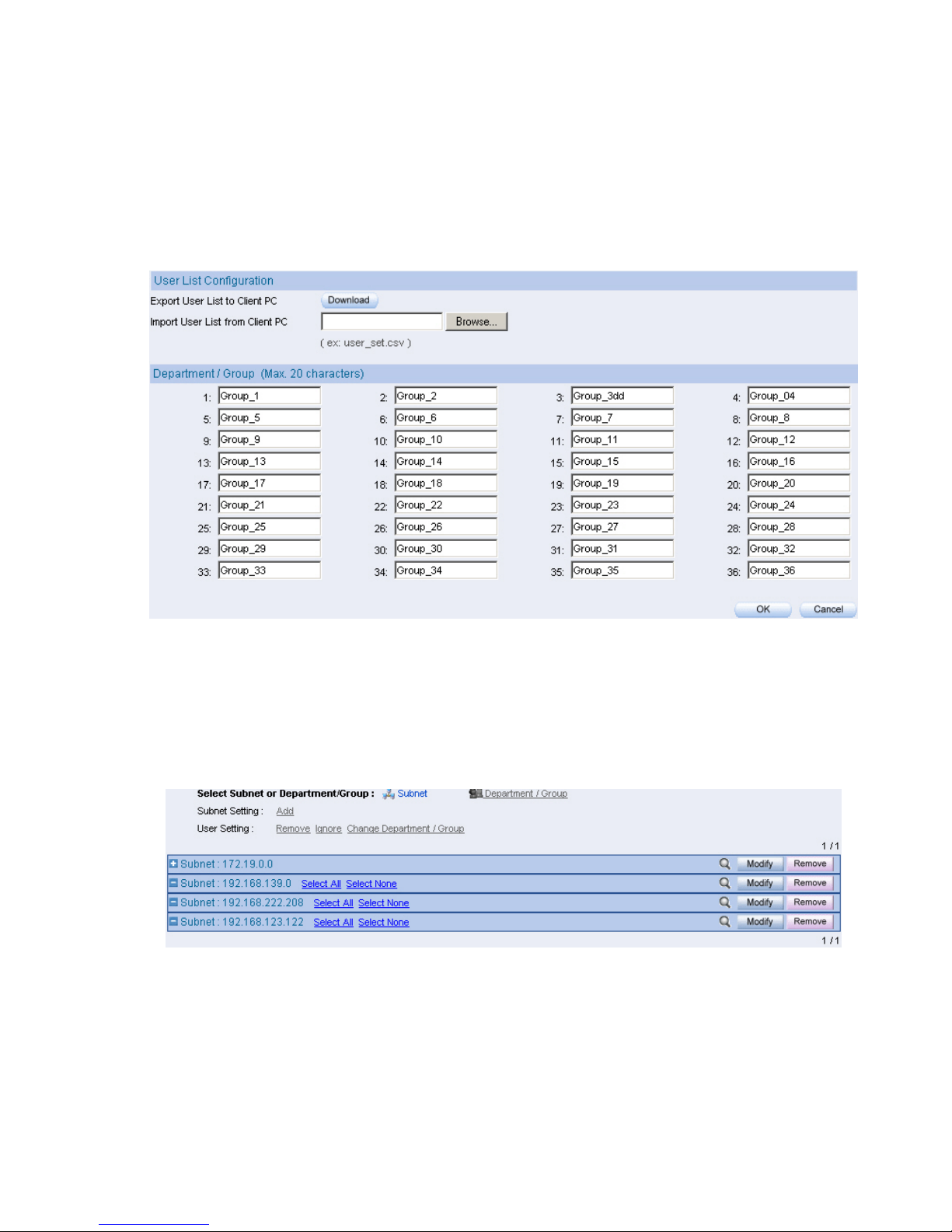
User Groups Management
Under User List Æ Setting, you can use your own name for the user groups, the number
of supported user groups may vary depends on which model of ICR appliance you have.
Figure 13, Set the name of department or group
Under User List Æ Logged, system will display the latest user list it captures in all the
subnets that have been configured in previous steps.
Figure 14, User List / Logged
21
3 System
The ICR appliance is managed by the main system administrator. The main system
administrator can add or delete any system settings and monitor the system status.
The other group administrator have no competency to modify the system settings (the
administrator’s name is set by the system main administrator), only can monitor the
system status.
Administration tasks on the ICR appliance include system configuration changes, user
account management, client PC management, system status monitoring and firmware
updates.
Physical network interfaces work differently according to the deployment:
– Bridge mode:
WAN port and LAN port works individually
– Sniffer mode:
WAN port serves as a packet receiver, it can be connected to the mirror port of a
core switch or a network hub.
LAN port can be connected to any other port available on that core switch for
system management by the administrative PC.
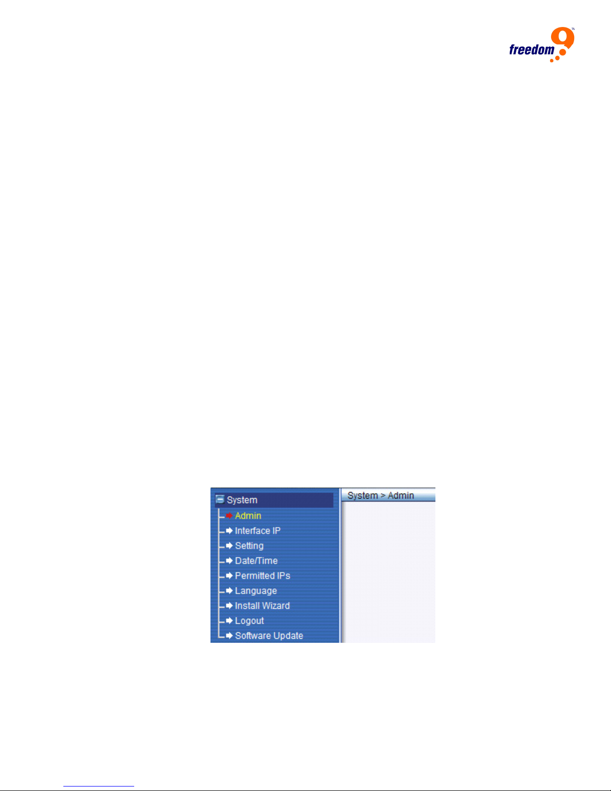
Interface Overview
Once you login to the Web interface of ICR appliance, under System menu you’ll find more
sub menus as shown below,
Figure 15, Menu – System
z Admin, create/remove the administration accounts for the ICR appliance
z Interface IP, configure the IP address for the ICR appliance and the protocol to
access through Web
z Setting, email alert settings, backup/restore configuration files and other advanced
settings
z Date/Time, system clock configuration
22

freeGuard Capture Appliance User’s Manual
z Permitted IPs, list of IP addresses that can login to the Web interface
z Language, language used for page display
z Install Wizard, wizard for quick and easy configuration
z Logout, logout from the Web interface
z Software Update, upgrade the firmware of ICR appliance
E-mail Setting under System/Setting, once configured, email alerts or reports will be sent
out according to the settings.
23

Administrator Accounts
Each ICR appliance has a built-in user name for administrative purpose, it’s called “admin”
by default, and it can’t be changed nor removed. System administrator has the privileges
to add/remove a group administrator and manage its privileges of accessing the ICR
appliance through the web interface. Administrators with both read and write access may
configure the system settings and view the system status.
Administrators with merely the read access can do nothing but view the system status. It
can also give an account of the READ privileges to specific user group/department, or
change the IP address of the unit and all other related settings.
Admin Account
Under System/Admin, you can find all the existing administrative accounts for the ICR
appliance.
In order to administrate the ICR appliance, the administration account is required.
“Admin” is the default login name for system administration, and it can not be changed
nor removed.
You can add more administration accounts, and assign the necessary access rights to the
ICR appliance, it can be “READ” and/or “Write” privileges.
The default administration account for ICR appliance is “admin”, and the password is “admin”.
Read/Write Privileges
The administrative account which has the privileges to Read and Write, can change the
system configurations, view the system status, to create or remove other administration
accounts.
The administration account which has the privileges to read only, can only view the
system status, but no change anything in the configuration of ICR appliance.
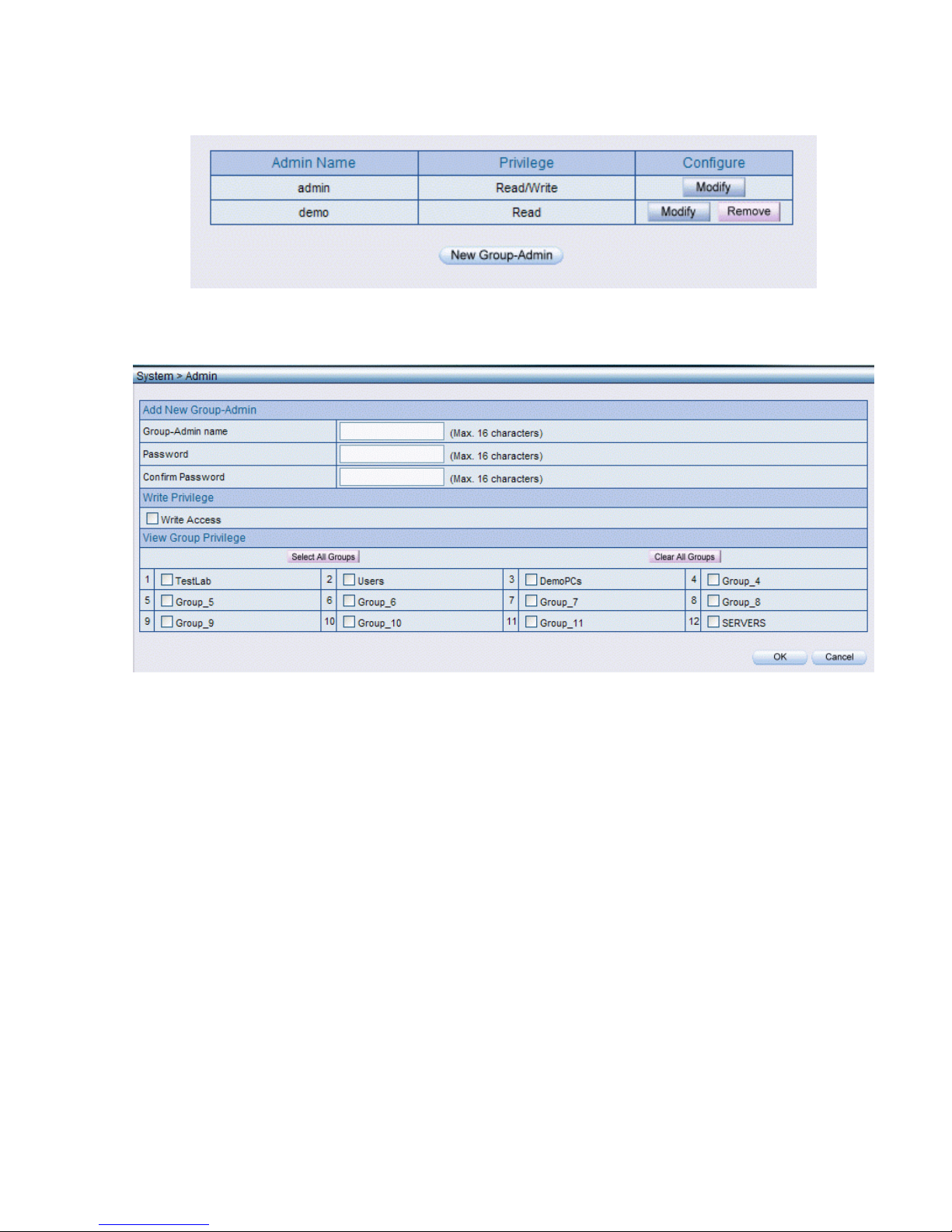
Group Administrator
Group administrators with write access are not allowed to change other administrator’s
account or the settings of its own.
To create a group administrator, click the “New Group-Admin” button under the list of the
existing accounts list.
24
freeGuard Capture Appliance User’s Manual
Figure 16, Create a Group Administrator – 1
Figure 17, Create a Group Administrator – 2
25

Interface IP
Setup Interface IP Address
Setup the IP address for the network interface for ICR appliance.
Figure 18, Interface IP address setup
Ping response can be enabled on the unit, so the unit will send back the response to the
PING test from the administrative PC.
Administrator can determine whether to enable the HTTP and HTTPS access to the ICR
appliance.
26
 Loading...