

Freedom9 4020 User Manual

freeStor 4020
4-bay Desktop Network Storage
USER’S MANUAL
P/N: N0042000
Rev. 2.5

Copyright and Trademark Information
Freedom9 makes no warranty or representation, expressed or implied, with respect to the
contents or use of this documentation. Freedom9 reserves the right to modify this
documentation at any time without obligation to notify any individual or entity of such
modifications.
© Copyright 2006, freeStor and the freedom9 company logo are trademarks or registered
trademarks of Freedom9 Inc. All rights reserved. No part of this document may be photocopied,
reproduced, or translated into another language without express prior to written consent of
Freedom9 Inc. Windows is a trademark or registered trademark of Microsoft Corporation. Other
trademarks or registered trademarks are the property of their respective holders.


TABLE OF CONTENTS
1 INTRODUCTION...................................................................................................... 1
1.1 TERMINOLOGY ..................................................................................................... 1
1.2 SYSTEM BENEFITS AND KEY FEATURES.................................................................. 1
1.3 PRODUCT SPECIFICATIONS.................................................................................... 2
1.4 FRONT PANEL ...................................................................................................... 3
1.5 PACKAGE CONTENTS ............................................................................................ 4
1.6 REAR PANEL ........................................................................................................ 4
1.7 REQUIREMENTS ................................................................................................... 4
2 INSTALLATION AND SETUP.................................................................................. 6
2.1 HARD DRIVE INSTALLATION.................................................................................... 6
2.2 STORAGE SYSTEM CONSOLE INSTALLATION............................................................ 7
2.3 SYSTEM SETUP.................................................................................................. 11
3 WEB MANAGEMENT INTERFACE ...................................................................... 17
3.1 MAIN MENU ....................................................................................................... 17
3.2 HOME................................................................................................................ 18
3.3 USERS .............................................................................................................. 20
3.4 GROUPS ............................................................................................................ 24
3.5 CHANGING THE AUTHENTICATION MODE ............................................................... 27
3.6 SHARED FOLDERS.............................................................................................. 33
3.7 MANAGING BACKUPS .......................................................................................... 38
3.8 EMAIL ALERTS.................................................................................................... 41
3.9 FIRMWARE UPDATES .......................................................................................... 43
3.10 USB DEVICES.................................................................................................... 44
3.11 SYSTEM SETTINGS ............................................................................................. 45
3.12 NETWORK SETTINGS .......................................................................................... 47
3.13 DISK CONFIGURATION......................................................................................... 48
3.14 SYSTEM STATUS................................................................................................. 53
3.15 SYSTEM LOG ..................................................................................................... 54
3.16 LOGGING OUT.................................................................................................... 54
3.17 SHUTTING DOWN ............................................................................................... 55
4 FILE SHARING AND SYSTEM BACKUP ............................................................. 56
4.1 FILE SHARING ....................................................................................................56
4.1.1 WINDOWS CLIENTS ............................................................................................................. 56
4.1.2 LINUX CLIENTS.................................................................................................................... 58
4.1.3 MAC CLIENTS...................................................................................................................... 59
4.1.4 FTP CLIENTS ...................................................................................................................... 59
4.2 SYSTEM BACKUP WITH DISKSAFE EXPRESS ......................................................... 60
4.2.1 SYSTEM REQUIREMENTS ..................................................................................................... 60
4.2.2 INSTALLING THE MICROSOFT ISCSI INITIATOR ....................................................................... 61
4.2.3 INSTALLING DISKSAFE EXPRESS ..........................................................................................62
i

freeStor 4020 User’s Manual
4.2.4 STAR TING DISKSAFE EXPRESS ............................................................................................65
4.2.5 ACT IVATI NG YOUR LICENSE KEY...........................................................................................66
4.2.6 PROTECTING YOUR DISKS ...................................................................................................68
4.2.7 MANUALLY BACKING UP YOUR DISKS ................................................................................... 74
4.2.8 STOPPING A BACKUP OR RECOVERY IN PROGRESS ...............................................................74
4.2.9 CHANGING THE BACKUP SCHEDULE ..................................................................................... 74
4.2.10 RECEIVING EVENT NOTIFICATIONS ....................................................................................... 75
4.2.11 CHANGING THE RECOVERY PASSWORD ................................................................................ 76
4.3 SYSTEM RESTORATION WITH DISKSAFE EXPRESS................................................. 77
4.3.1 RECOVERING FILES FROM A BACKUP.................................................................................... 78
4.3.2 RECOVERING A NON-SYSTEM DISK OR PARTITION.................................................................79
4.3.3 RECOVERING A SYSTEM DISK OR PARTITION USING THE RECOVERY CD .................................80
4.3.4 RECOVERING A SYSTEM DISK OR PARTITION USING REMOTE BOOT........................................ 84
4.3.5 REMOVING PROTECTION...................................................................................................... 88
ii

TABLE OF FIGURES
FIGURE 1-1: FRONT PANEL ........................................................................................... 3
FIGURE 1-2: REAR PANEL ............................................................................................. 4
FIGURE 2-1: HARD DRIVE TRAY ..................................................................................... 6
FIGURE 2-2: SATA CONNECTOR.................................................................................... 6
FIGURE 2-3: ATTACHING THE HARD DRIVE TO THE TRAY .................................................. 7
FIGURE 2-4: WELCOME PAGE........................................................................................ 8
FIGURE 2-5: LICENSE AGREEMENT ................................................................................ 8
FIGURE 2-6: CUSTOMER INFORMATION........................................................................... 9
FIGURE 2-7: DESTINATION LOCATION .............................................................................9
FIGURE 2-8: SUMMARY ...............................................................................................10
FIGURE 2-9: INSTALLATION COMPLETE ......................................................................... 10
FIGURE 2-10: STORAGE SYSTEM CONSOLE.................................................................. 11
FIGURE 2-11: SYSTEM INITIALIZATION SCREEN ............................................................. 12
FIGURE 2-12: WELCOME SCREEN ............................................................................... 13
FIGURE 2-13: END USER SOFTWARE LICENSE AGREEMENT........................................... 13
FIGURE 2-14: HOST NAME .......................................................................................... 14
FIGURE 2-15: DATE/TIME............................................................................................ 14
FIGURE 2-16: NETWORK SETTINGS ............................................................................. 15
FIGURE 2-17: DISK CONFIGURATION ............................................................................ 15
FIGURE 2-18: DISK SPACE DISTRIBUTION..................................................................... 16
FIGURE 2-19: SYSTEM CONFIGURATION....................................................................... 16
FIGURE 3-1: LOGIN SCREEN........................................................................................ 17
FIGURE 3-2: MAIN MENU ............................................................................................ 17
FIGURE 3-3: HOME PAGE ............................................................................................ 18
FIGURE 3-4: CONNECTIONS PAGE................................................................................ 19
FIGURE 3-5: USERS PAGE........................................................................................... 20
FIGURE 3-6: ADD USER PAGE...................................................................................... 21
FIGURE 3-7: CIFS ADD USER PAGE............................................................................. 22
FIGURE 3-8: NFS ADD USER PAGE.............................................................................. 22
FIGURE 3-9: GROUPS PAGE ........................................................................................ 24
FIGURE 3-10: ADD GROUP PAGE ................................................................................. 25
FIGURE 3-11: AUTHENTICATION MODE PAGE ................................................................ 28
FIGURE 3-12: ACTIVE DIRECTORY SERVER SETTINGS PAGE .......................................... 29
FIGURE 3-13: ACTIVE DIRECTORY USER LOGIN PAGE ................................................... 29
FIGURE 3-14: ACTIVE DIRECTORY TREE PAGE .............................................................. 30
FIGURE 3-15: ACTIVE DIRECTORY ADMINISTRATOR LOGIN PAGE .................................... 31
FIGURE 3-16: UPDATE AUTHENTICATION MODE PAGE.................................................... 32
FIGURE 3-17: SHARED FOLDERS PAGE ........................................................................ 33
FIGURE 3-18: ADD SHARED FOLDER PAGE................................................................... 34
FIGURE 3-19: CIFS ADD SHARED FOLDER PAGE .......................................................... 35
FIGURE 3-20: CIFS DEFINE FOLDER PERMISSIONS PAGE.............................................. 35
FIGURE 3-21: NFS DEFINE FOLDER PERMISSIONS PAGE............................................... 36
FIGURE 3-22: BACKUPS PAGE..................................................................................... 38
iii

freeStor 4020 User’s Manual
FIGURE 3-23: ALERTS PAGE........................................................................................ 42
FIGURE 3-24: FIRMWARE PAGE ................................................................................... 44
FIGURE 3-25: USB PAGE............................................................................................ 44
FIGURE 3-26: SYSTEM PAGE ....................................................................................... 46
FIGURE 3-27: NETWORK PAGE ....................................................................................47
FIGURE 3-28: DISKS PAGE .......................................................................................... 49
FIGURE 3-29: EXPAND SHARED STORAGE PAGE ........................................................... 50
FIGURE 3-30: DISK CONFIGURATION PAGE ................................................................... 51
FIGURE 3-31: DISK SPACE DISTRIBUTION PAGE ............................................................ 52
FIGURE 3-32: DISK CONFIGURATION STATUS PAGE ....................................................... 52
FIGURE 3-33: DISK CONFIGURATION COMPLETION PAGE ............................................... 53
FIGURE 3-34: SYSTEM STATUS PAGE ........................................................................... 53
FIGURE 3-35: SYSTEM LOG PAGE................................................................................ 54
FIGURE 3-36: SHUT DOWN PAGE................................................................................. 55
FIGURE 4-1: MAP NETWORK DRIVE ............................................................................. 57
FIGURE 4-2: DISKSAFE EXPRESS WELCOME PAGE ....................................................... 63
FIGURE 4-3: DISKSAFE EXPRESS LICENSE AGREEMENT................................................ 63
FIGURE 4-4: DISKSAFE EXPRESS DESTINATION FOLDER ............................................... 64
FIGURE 4-5: DISKSAFE EXPRESS INSTALLATION COMPLETED......................................... 64
FIGURE 4-6: DISKSAFE EXPRESS LICENSE DIALOG ....................................................... 65
FIGURE 4-7: DISKSAFE EXPRESS APPLICATION............................................................. 66
FIGURE 4-8: DISKSAFE EXPRESS DISK SELECTION ....................................................... 68
FIGURE 4-9: ADD STORAGE SYSTEM PAGE................................................................... 70
FIGURE 4-10: STORAGE SYSTEM SELECTION PAGE....................................................... 70
FIGURE 4-11: BACKUP SCHEDULE PAGE.......................................................................71
FIGURE 4-12: RECOVER CD PASSWORD PAGE ............................................................. 73
FIGURE 4-13: DISKSAFE EXPRESS COMPLETION PAGE ................................................. 73
FIGURE 4-14: DISKSAFE EXPRESS SCHEDULE PAGE..................................................... 75
FIGURE 4-15: DISKSAFE EXPRESS RECOVERY PAGE ....................................................76
FIGURE 4-16: DISKSAFE EXPRESS PASSWORD RESET.................................................. 77
FIGURE 4-17: ENABLE REMOTE BOOT DIALOG.............................................................. 85
FIGURE A-1: DISK CHANGE NOTIFICATION PAGE ........................................................... 92
FIGURE A-2: DISK CHANGE NOTIFICATION PAGE – NEW DISK......................................... 93
FIGURE A-3: DISK CHANGE NOTIFICATION PAGE – DEGRADATION................................... 94
iv

1 Introduction
The freeStor 4020 is an intelligent network storage solution for small office, medium office, and
home network environments. The freeStor 4020 features an integrated file server with system
backup, system recovery, and managed shared files by user names or groups. The freeStor
4020 can connect to a Gigabit Ethernet network and can support up to 4 3.5” SATA (serial
advanced technology attachment) hard disk drives (HDD). Its high performance is ideal for
protecting valuable company data, and quickly restoring files from a backup. The freeStor 4020
offers a convenient graphical web user interface, and provides security by limiting access to
shared folders by user or group level authentication.
The freeStor 4020 provides a complete and advanced data backup/protection solution including
RAID and DiskSafe Express (DSE). The freeStor 4020 supports standard RAID levels 0, 1, 5
and 10. DSE is a powerful function to provide entire system backup and recovery for clients
running Windows 2000, Windows XP or Windows Server 2003 in the event of hard disk failure
in the client.
1.1 Terminology
For clarity, the OS X operating system will be referred to as “OS X” and Mac 9.0 and earlier
operating systems will be referred to as “Mac” throughout the manual.
1.2 System Benefits and Key Features
• Music, Video, and Data file sharing among Windows, Linux, Unix and Macintosh users with
username and password protected and managed access.
• Can act as a DHCP server or DHCP client for easy network configuration.
• Easy file sharing management via a user-friendly graphical web interface.
• Setup wizard for easy initial configuration.
• Supports authentication using a local database or Active Directory.
• DSE provides system and data backup, remote boot and system and data restoration for
Windows 2000, Windows XP and Windows Server 2003 clients.
• Built-in FTP server provides convenient high-speed file transfers.
• System software upgrade via web interface.
• RAID 0, 1, 5, and 10 support.
• System information for disk usage, service status, RAID, system log and current
connections.
1

freeStor 4020 User’s Manual
1.3 Product Specifications
Hardware Specifications
Processor
Memory
Flash
HDD
Maximum Capacity
Network
SATA Controller
USB
EMI Safety
System Power
Operating Temperature
Operating Humidity
Non-Operating Temperature
Storage Temperature
Storage Humidity
Dimensions
Weight (without drives)
Intel 80219 IOP 400 MHz
DDR 256 MB
8 MB NOR Flash
Up to four 3.5” SATA-I, II Hard Disks from 80GB to 500GB
Up to 2.0TB
One Intel gigabit LAN port interface
Intel SATA Controller
2 x USB 2.0 connectors
CE/FCC Class B
220W PSU
32ºF to 104ºF (0ºC to 40ºC)
10% to 90% relative humidity
32ºF to 104ºF (0ºC to 40ºC)
-4ºF to 158ºF (-20ºC to 70ºC)
5% to 90% non-condensing
4.53 x 9.45 x 8.27 in (11.5 x 24 x 21 cm)
9.9 lb (4.5 kg)
Software Specifications
Client OS Supported
Microsoft Windows 2000 with Service Pack 2, Microsoft
Windows XP/2003, UNIX, Mac OS 7.X and later, Linux
Network Protocols
Client Support Capabilities
Network Service
CIFS/SMB/NFS, FTP, HTTP, HTTPS
Max. 64 Clients, 16 Groups, 32 Shared Folders
DHCP Client/Server (default is DHCP client, with a static
IP address of 192.168.0.101 if a DHCP server cannot be
found)
Supported Web Browsers
Microsoft Internet Explorer 6.0 or newer, Mozilla Firefox
1.06 or newer
RAID Levels
DiskSafe Express Licenses
RAID 0, 1, 5, 10
2 Included, Maximum of 16
USB Port Limitations
The freeStor 4020 is designed to work with up to two USB devices. The USB devices can either
be printers or external storage devices (hard drives or flash drives). The following limitations
apply:
• USB hubs are not supported
• The freeStor 4020 cannot be connected directly to a computer’s USB port.
• For external storage devices, only the first partition in a multi-partition drive is supported,
and only FAT or FAT32 partitions are supported.
• Multi-function printers (such as printers that perform copying, scanning, or faxing in addition
to printing), Windows Printing System (WPS), Non-PostScript printing (Mac) and Duplexonly (two-way) communication printers are not supported.
Note: Refer to your printer’s documentation for information about disabling
duplex communication. With some duplex printers, printing might complete
2
successfully, although errors might occur. In addition, some features (such as the
printer reporting low ink levels) might not function since two-way communication
is not supported.
1.4 Front Panel
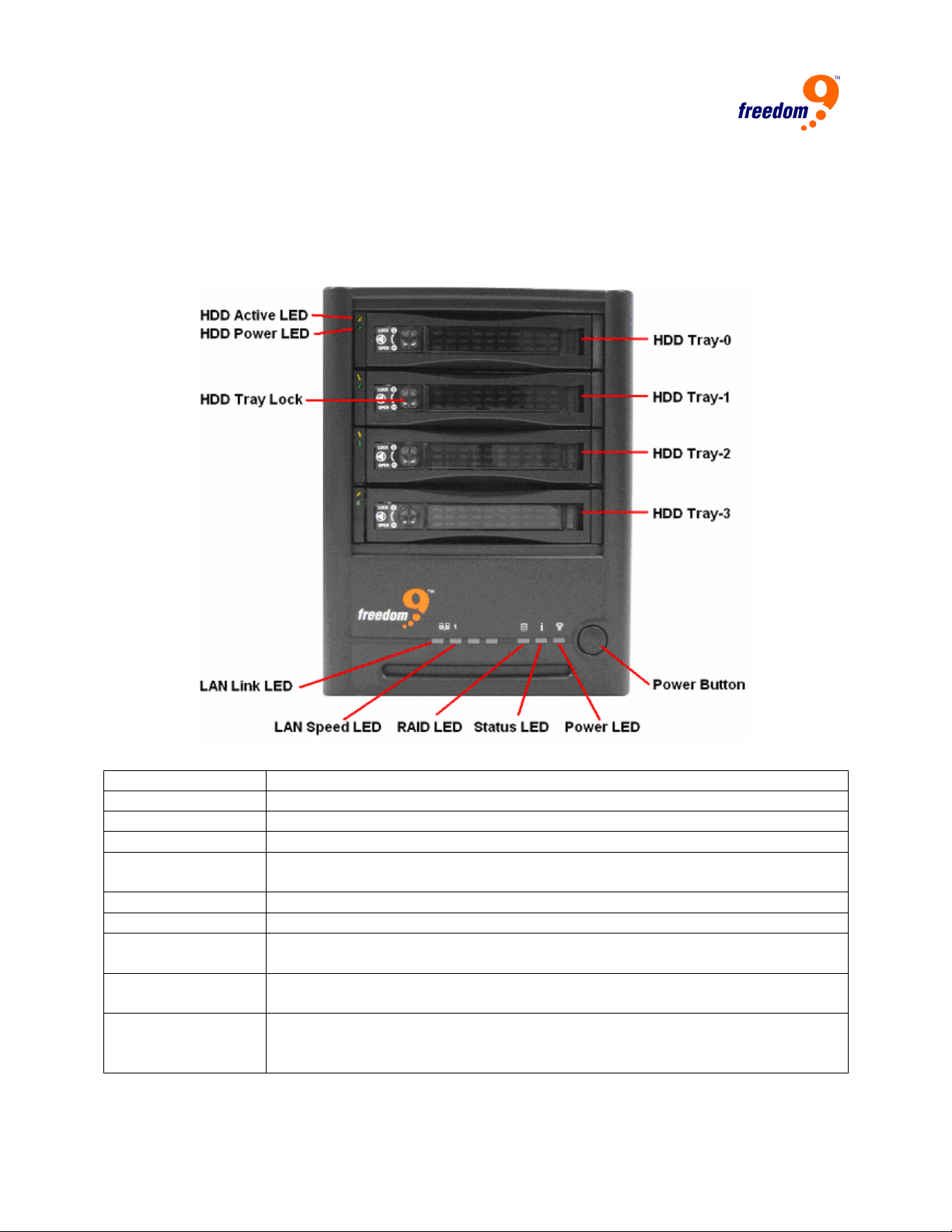
The front panel (Figure 1-1) contains the power button, hard disks, and status LEDs.
Figure 1-1: Front Panel
HDD Active LED
HDD Power LED
HDD tray lock
LAN Link LED
LAN Speed LED
This LED flashes GREEN when the HDD is active.
This LED lights up GREEN when the HDD is installed properly.
Turn the lock horizontally to lock the tray in place, or vertically to unlock it.
This LED will flash ORANGE if the network interface is being used.
This LED will light up ORANGE when connected to a gigabit connection,
and GREEN when connected to a 10/100 Mbps connection.
HDD Trays
Power LED
Power button
Four 3.5-inch SATA HDD trays.
This LED lights up BLUE when the system is powered on.
Press this to turn the unit on, and press and hold until the Status and RAID
LEDs start flashing to turn it off.
Status LED
This LED lights up BLUE when the hard disks reach their maximum
storage capacity.
RAID LED
This LED lights up RED when RAID 0 is used, ORANGE when RAID 1 or
RAID 10 is used, GREEN when RAID 5 is used, and is off if no RAID is
used.
3
freeStor 4020 User’s Manual
1.5 Package Contents
• freeStor 4020 unit
• One power cord
• One RJ-45 cable
• DSE Boot CD
• Device management utility, DSE client, firmware and user’s manual CD
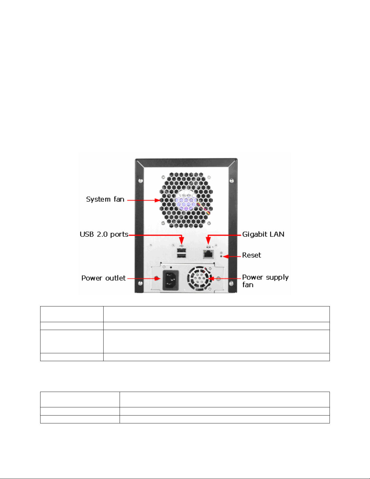
1.6 Rear Panel
The rear panel (Figure 1-2) contains the system fan, power supply, USB 2.0 ports, gigabit LAN
port, power cord connection, and reset button.
Figure 1-2: Rear Panel
USB 2.0 Ports
The USB ports can be used to connect USB printers and external storage
to the freeStor 4020.
Power Outlet
Gigabit LAN Port
Supplies power to the device.
Gigabit Ethernet connection. The right LED lights up GREEN when
connected to a 10/100 Mbps network, and ORANGE when connected to a
gigabit network.
Reset Button
Press the “Reset” button for three seconds the unit to system defaults.
1.7 Requirements
Before using the freeStor 4020, the following minimum requirements must be met:
Web Browser
Network Environment
Serial ATA hard disk
Microsoft Internet Explorer 6.0 or above or Mozilla Firefox 1.06 or
above
TCP/IP network environment
At least one Serial ATA HDD installed with at least 80GB capacity
4

All clients using DSE must meet the following requirements:
BIOS
Operating System
Client PCs must be able to boot from a CD
Windows Server 2003, Windows XP, or Windows 2000 (Professional,
Server, or Advanced Server) with Service Pack 2 or above.
Note: The operating system must be installed on the first partition (Drive
C).
LAN port
At least one wired NIC
5
freeStor 4020 User’s Manual
2 Installation and Setup
2.1 Hard Drive Installation
It is highly recommended that all of the hard drives used are the same size. However, if they are
different sizes, it is recommended that the drives are placed from largest to smallest from the
top tray to the bottom tray.
Note: At least one SATA hard disk with at least 80 GB capacity must be installed
before the unit can be used. The unit does not ship with any hard drives installed.
Follow these steps to install a hard drive into the unit:
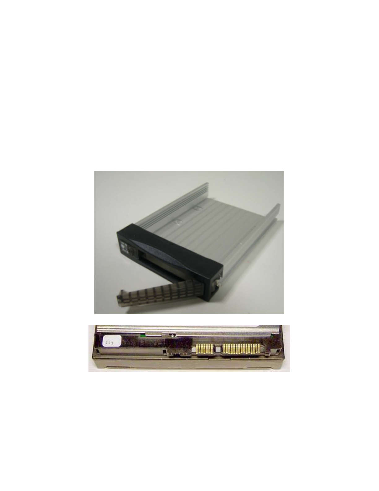
1. Remove the topmost hard drive tray (Figure 2-1) from the freeStor 4020.
Note: Ensure that the hard drive is a SATA drive (Figure 2-2) and not an ATA or
SCSI drive.
Figure 2-1: Hard Drive Tray
Figure 2-2: SATA Connector
6
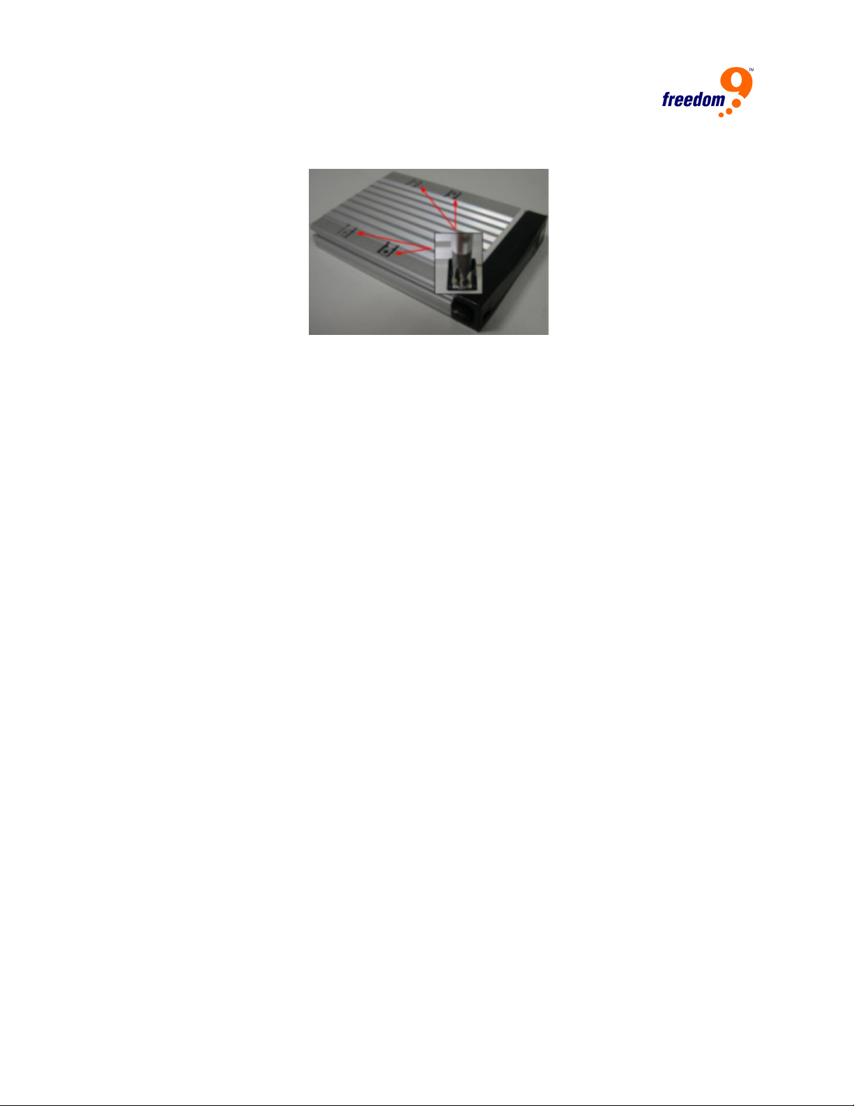
2. Slide the new hard drive into the tray and fasten the screws underneath the tray (Figure 2-
3).
Figure 2-3: Attaching the Hard Drive to the Tray
3. Pull out the handle before inserting the hard drive tray into the freeStor 4020.
4. After the tray has been inserted, push the handle back into position to lock the tray in place.
5. Repeat steps 1-4 for the remaining hard drives that need to be installed.
6. Connect the power cable to the back of the freeStor 4020 and plug the other end of the
cable into a power socket.
7. Press the power button on the front of the freeStor 4020.
8. The Status LED will flash while the unit is booting up. Once the unit has finished booting up,
the Status LED will turn off.
9. Once the unit has powered up, the hard drive LED will flash green and the power LED will
light up blue on the drive tray. If the hard drive LED is flashing red, there is a problem with
the drive installation and the drive should be removed, tested, and reinstalled again using
the above procedure.
Notes:
• If you replace all of the drives with higher capacity, you have to go to
Administrator to login and format the drives. This will cause all data and
backups to be deleted.
• It is recommended that the freeStor 4020 be plugged into a surge protector or
uninterruptible power supply (UPS) to prevent damage to the unit from power
surges.
2.2 Storage System Console Installation
The Storage System Console is a Windows application included with the freeStor 4020. The
software allows you to discover and access all freeStor 4020’s on the network. Although not
required, the Storage System Console makes configuring and managing the units much easier.
The Storage System Console runs on the following operating systems: Microsoft Windows 2000
with Service Pack 2 or higher, Microsoft Windows XP, Microsoft Windows Server 2003.
To install the Storage System Console, follow these steps:
1. Insert the Installation CD into your CD-ROM drive.
2. In Windows Explorer, open the “StorageSystemConsole” folder on the installation CD.
7
freeStor 4020 User’s Manual
Double-click the “Setup.exe” file to begin installation of the software.
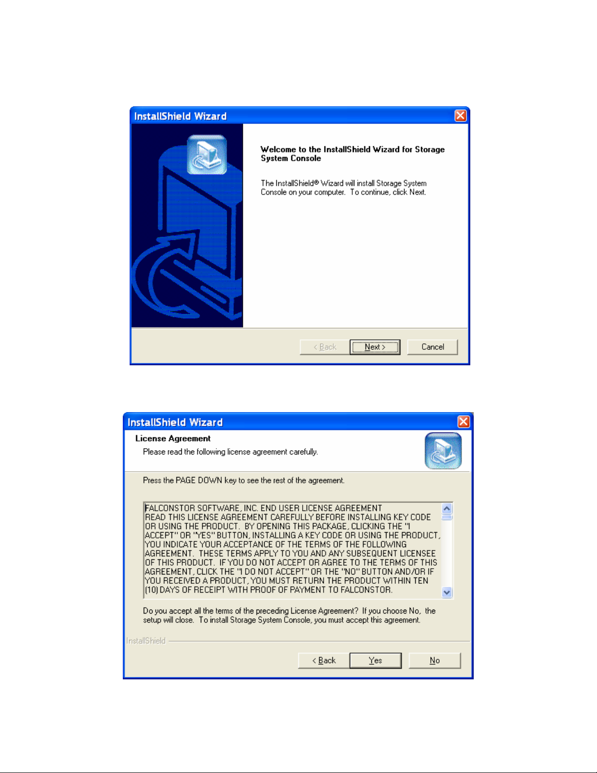
3. On the welcome page (Figure 2-4), click “Next”.
Figure 2-4: Welcome Page
4. Click “Yes” if you agree to the terms of the license agreement (Figure 2-5). If you do not
agree to the terms, you cannot install the software.
Figure 2-5: License Agreement
8
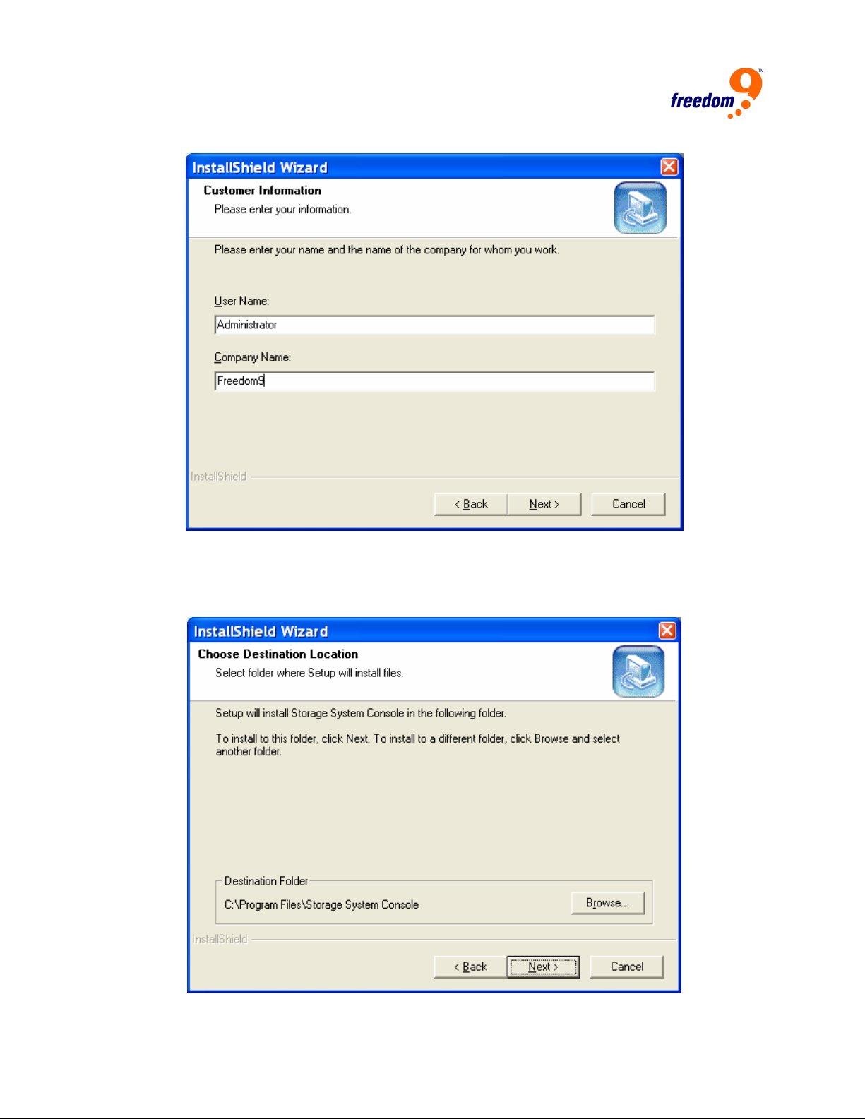
5. On the next page (Figure 2-6), enter your name and company name and then click “Next”.
Figure 2-6: Customer Information
6. On the following page (Figure 2-7), click “Next” to install the Storage System Console in the
displayed location, or click “Browse…” to select or specify a different location and then click
“Next”.
Figure 2-7: Destination Location
9
freeStor 4020 User’s Manual
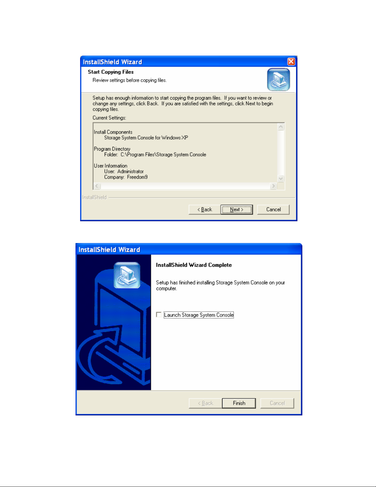
7. Review your selections and click “Next” to proceed (Figure 2-8).
Figure 2-8: Summary
8. To complete the installation, click “Finish” (Figure 2-9).
Figure 2-9: Installation Complete
Note: If the freeStor 4020 is not directly connected to your computer and your
network does not have a DHCP server, you must change the IP address of your
10
computer to use the same subnet as the storage system. (You can change it
back after you have configured the storage system.) To do this, access your local
area network properties. (For example, you might right-click “My Network Places”
and click “Properties”, and then right-click your network connection and click
“Properties”.) In the list, select “Internet Protocol (TCP/IP)” and click “Properties”.
The IP address can be any address beginning with “192.168.0” except
“192.168.0.101”, since that’s the IP address used by the storage system. The
subnet mask must be “255.255.255.0”. Then click “OK” to close each open dialog
box. When you configure the unit, you can specify whatever IP address you
would like the storage system to use. If the IP address of the storage system is in
a different subnet than your computer, you must also specify the gateway to use.
This ensures that you can manage the storage system from any computer using
a Web browser. Then you can change your computer’s IP address back to its
original setting.
Once the Storage System Console has been installed, run the program from the Start Menu
(Start Æ Programs Æ Storage System Console).
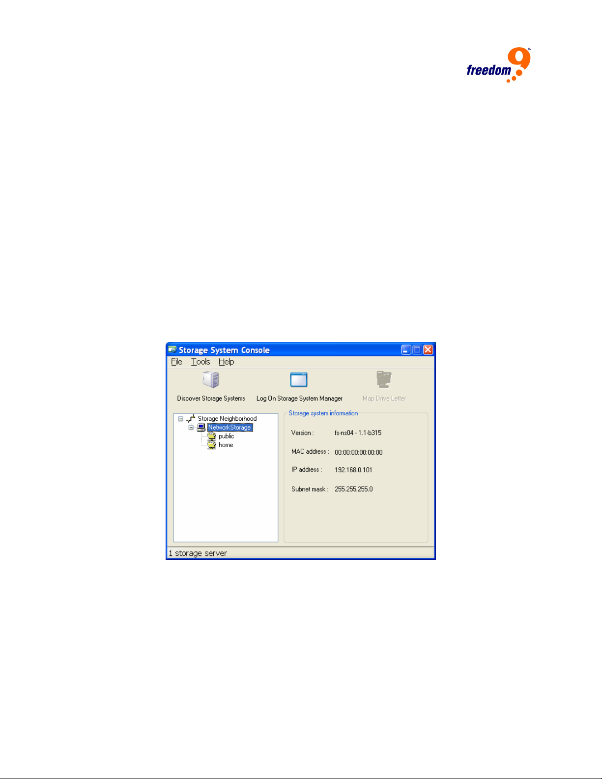
When the Storage System Console starts, it will automatically scan the network for freeStor
4020 devices. After the scan is complete, the devices found will be listed in the left pane (Figure
2-10).
Figure 2-10: Storage System Console
In the left pane, select the name of the new unit and click “Log On Storage System Manager” to
access the web interface of the device.
If any freeStor 4020 units are added to the network after the software has started, click
“Discover Storage Systems” to rescan the network for the new units.
2.3 System Setup
Once the hard drives have been successfully installed, the freeStor 4020 will have to be
configured before it can be used. Follow these steps to configure the device.
11
freeStor 4020 User’s Manual
1. Connect the freeStor 4020 to your network. If your network has a DHCP server, the freeStor
4020 will automatically get an IP address from the DHCP server. Otherwise, the freeStor
4020 will default to an IP address of 192.168.0.101.
2. Plug in and power on the freeStor 4020.
3. The web interface of the freeStor 4020 can be accessed by using the Storage System
Console (see Section 2.2) or by using a web browser. For access using a web browser,
open up a web browser (Internet Explorer 6.0 or higher or Mozilla Firefox 1.06 or higher) and
enter “https://” followed by the IP address of the unit in the address bar (e.g.
https://192.168.0.101). Note that the freeStor 4020 only supports https access to the web
GUI, and not HTTP. If you are accessing the device through a router or firewall, ensure that
port 443 is forwarded to the freeStor 4020.
4. For both connection methods, the web browser will be connected to the freeStor 4020 and
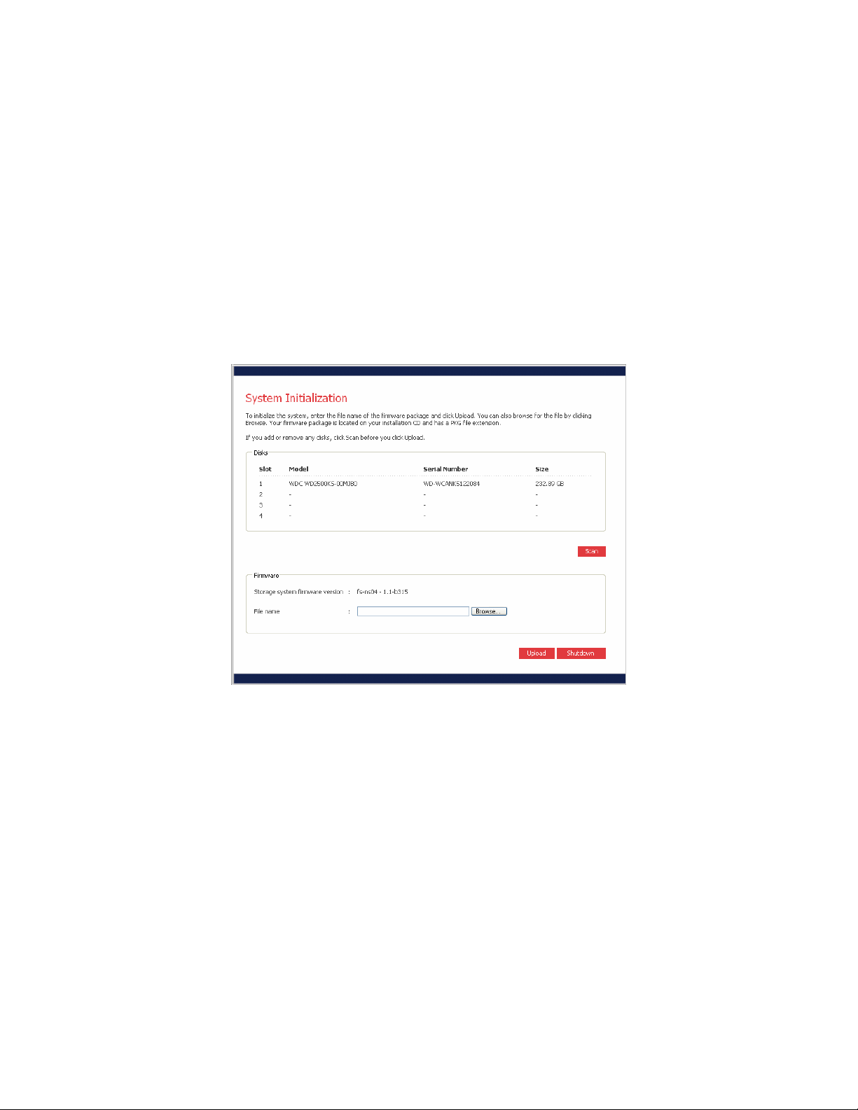
the System Initialization screen will be displayed (Figure 2-11).
Figure 2-11: System Initialization Screen
5. The System Initialization screen will list the model, serial number, and size of the hard drives
installed in the unit. If a hard drive is added or removed after loading this page, click “Scan”
to refresh the list of hard drives.
Note: If you have four disks that are not the same size, it is recommended that
you put disks close in size in slots 1 and 2. For example, if one disk is 100 GB,
one disk is 200 GB, one disk is 300 GB, and one disk is 400 GB, it is
recommended that you put the 100-GB disk in slot 1 and the 200-GB disk in slot
2 (rather than putting the 100-GB disk in slot 1 and the 300- or 400-GB disk in
slot 2). This ensures that, if you choose a RAID 10 configuration when you
subsequently configure the storage system, the amount of disk space available
for data is maximized.
6. Click “Browse” and navigate to the firmware file on the CD-ROM. The firmware has a file
extension of “.pkg”. Select the file and click “Open”.
7. Click “Upload” to upload the firmware to the hard disks in the unit. Once the firmware has
finished uploading, the unit will automatically restart.
12
Note: The operating system and software are installed on each disk in your
storage system to ensure that the failure or removal of any one disk will not
cause the entire storage system to fail.
8. After the unit has restarted, connect to the device again using steps 1 through 3.
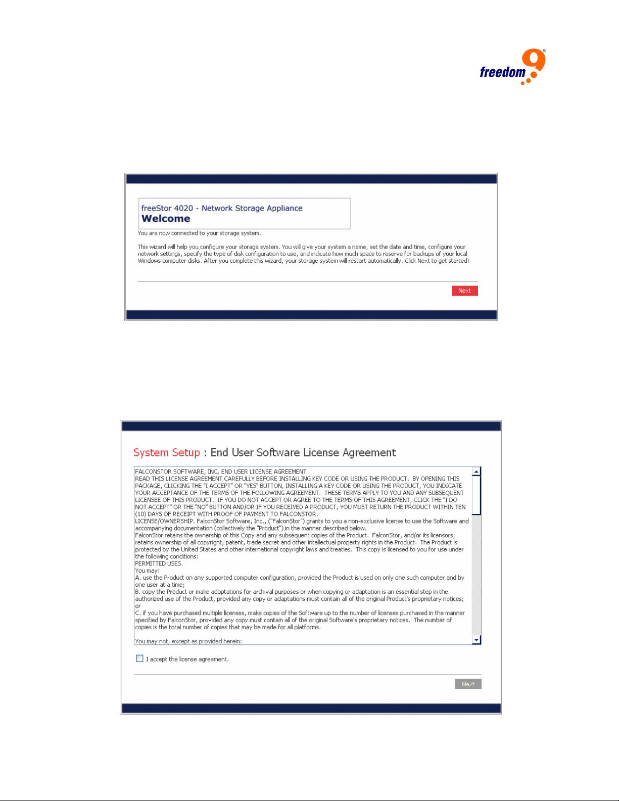
9. Once the web browser is open, a welcome screen will be displayed (Figure 2-12).
Figure 2-12: Welcome Screen
10. Click “Next” to proceed to the next page.
11. The next page contains the End User Software License Agreement (Figure 2-13). If you
agree to the terms, click on the “I accept the license agreement” check box and click “Next”.
Note: You cannot use the freeStor 4020 if you do not agree to the terms in the
End User Software License Agreement.
Figure 2-13: End User Software License Agreement
13
freeStor 4020 User’s Manual
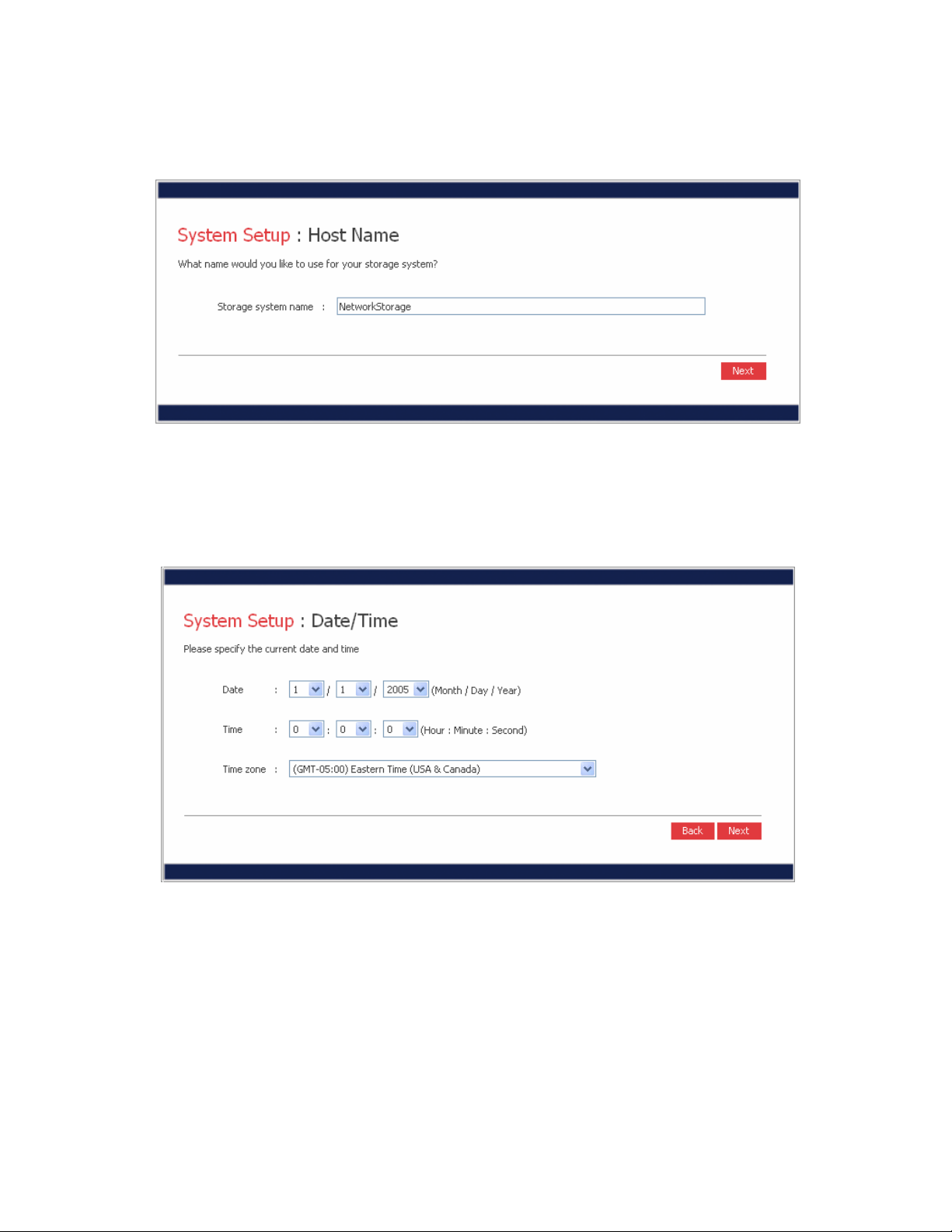
12. On the next page, enter a host name to identify the freeStor 4020 on the network (Figure 2-
14). The system name can be up to 15 characters long and can only include letters,
numbers, and hyphens. To proceed, click “Next”.
Figure 2-14: Host Name
13. On the next page, enter the current date and time (Figure 2-15). The time must be entered
in 24-hour notation (2:15 PM should be entered as 14:15). After entering the date and time,
click “Next”.
Note: The freeStor 4020 time does not automatically change to reflect daylight
savings time. To accommodate this, you can manually adjust the time as needed.
Figure 2-15: Date/Time
14
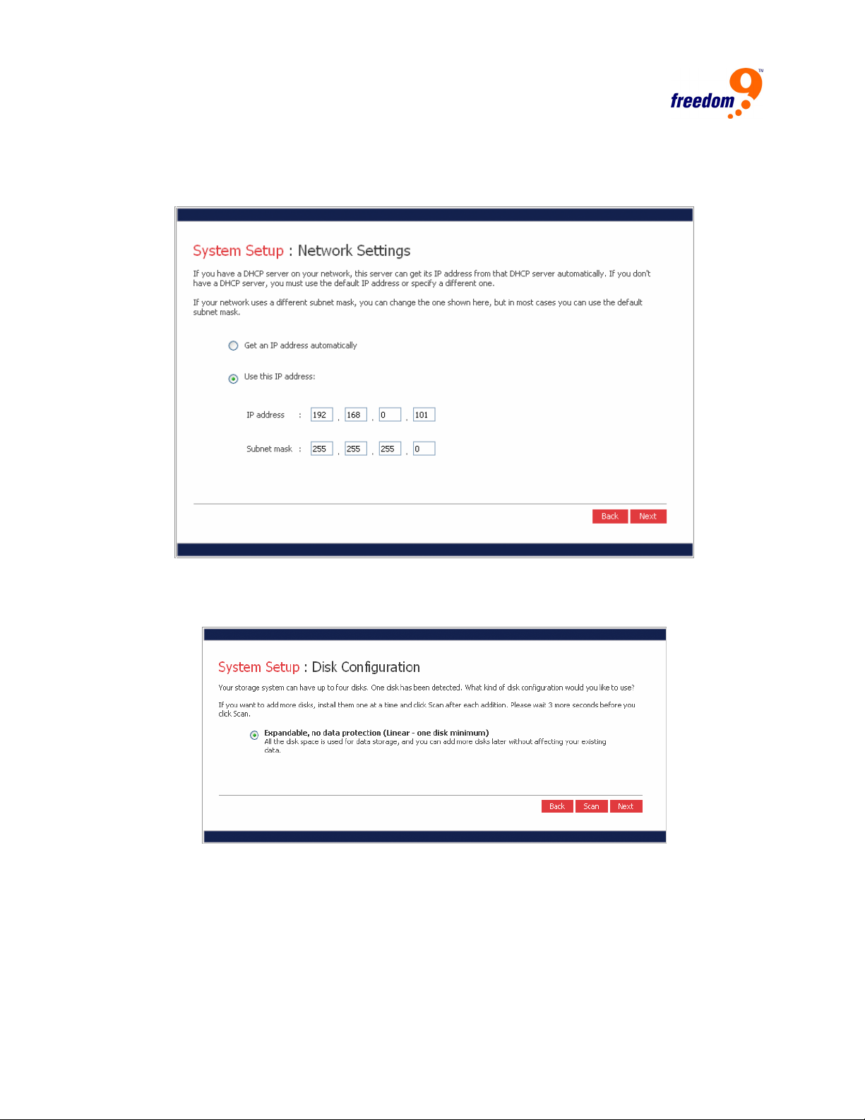
14. On the next page, enter the network settings of the freeStor 4020 (Figure 2-16). If the
network has an existing DHCP server, select “Get an IP address automatically”. Otherwise,
select “Use this IP address” and enter the desired IP address below. After entering the
network settings, click “Next”.
Figure 2-16: Network Settings
15. The next page will ask for the disk configuration to use for the freeStor 4020 (Figure 2-17).
The options presented on the page vary depending on the number of hard drives in the unit.
Figure 2-17: Disk Configuration
16. To add or remove hard drives from the freeStor 4020 at this time, add or remove one drive at
a time, and click “Scan” before adding or removing the next drive.
Note: It is strongly recommended that all of the drives that you want to use in the
final configuration be installed at this time. Adding or removing drives after this
step could require drive reconfiguration and data loss.
17. To accept the default disk configuration (which will provide the best level of data protection
available for the number of hard disks currently installed), click “Next”. By default, a linear
15
freeStor 4020 User’s Manual
disk configuration is used for a single hard disk, RAID 1 is used for two hard disks, and
RAID 5 is used for three or four hard disks.
18. To change the disk configuration, select the desired RAID level and then click “Next”.
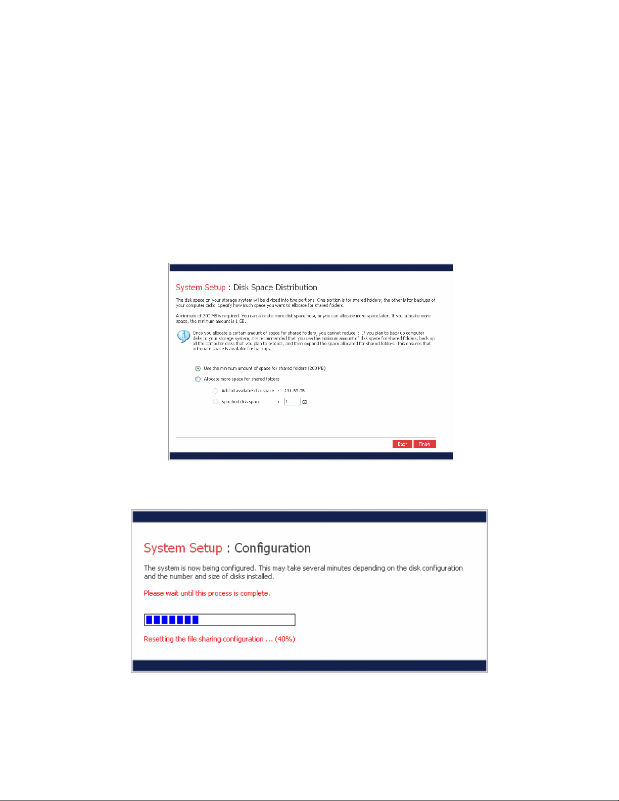
19. On the following page, you can select how much space to allocate to shared folders and to
backup (Figure 2-18). To change the allocation, enter the desired amount of space to use for
shared folders. The remaining amount will be used for backups. Click “Finish” when ready
to proceed, then click “OK” when the confirmation page appears.
Note: Once the wizard is completed, reducing the disk allocation for shared
folders in the future will result in the deletion of all data on the freeStor 4020. If
you plan to back up computers to the unit, it is recommended that you use the
minimum amount of space for shared folders, back up all the computers that you
plan to protect, and then expand the space allocated for shared folders. This
ensures that adequate space is available for backups.
Figure 2-18: Disk Space Distribution
20. The configuration page (Figure 2-19) will appear to show the progress of the system setup.
Once the setup is complete, the system will restart automatically.
Figure 2-19: System Configuration
After the unit restarts, the web management interface can be used to add users and create
shared folders to start using the freeStor 4020.
16
3 Web Management Interface
The web management interface can be accessed using a web browser directly connecting to
the IP address of the freeStor 4020, or the Storage System Console (see Section 2.2).
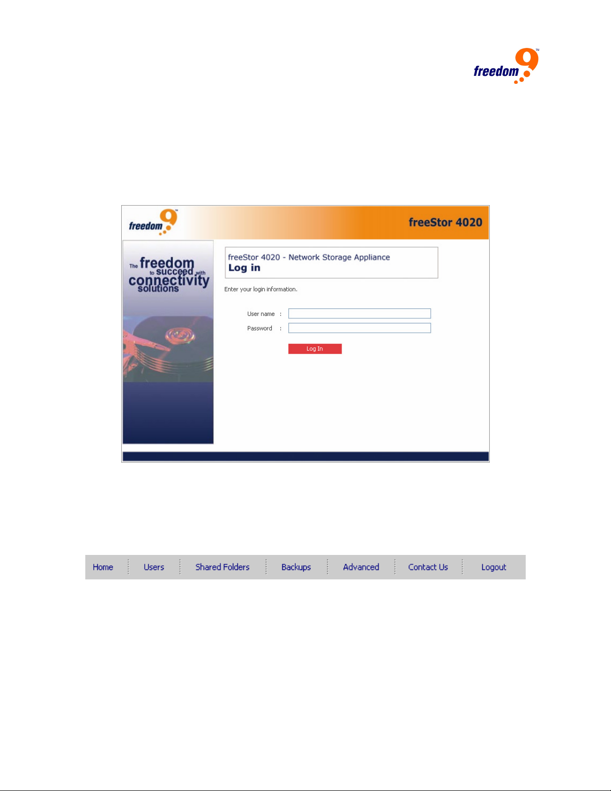
When first accessing the web interface, the login screen (Figure 3-1) will appear. Enter the user
name and password and click “Login”. The default user name is “admin” and the default
password is “storage”. It is recommended that the password be changed as soon as possible for
security reasons.
Figure 3-1: Login Screen
3.1 Main Menu
After logging in, the Home page will be displayed on the screen. The main menu (Figure 3-2) is
displayed along the top of every page and allows you to access all of the freeStor 4020’s
features. The main menu has the following items:
Figure 3-2: Main Menu
• Home: Displays information about the total storage capacity on the storage system, how
much disk space is allocated for shared folders, how much is allocated for backups, and
how much is used for each. This page also displays the total number of shared folders and
the number of networked computers (backup clients) that have backed up one or more disks
on the storage system.
• Users: Displays a list of all currently configured users. If you’re using local authentication
mode, you can add, modify, and remove all types of users, and add, modify, and remove
groups of Windows and Mac OS X users. If you’re using Active Directory authentication
mode, you can add, modify, and remove Linux users and other Mac users. You can also use
17
freeStor 4020 User’s Manual
this page to change the authentication mode.
• Shared Folders: Displays a list of all currently configured shared folders and lets you add
shared folders, change which users can access them, and remove them.
• Backups: Displays a list of all computer disk backups that currently exist and lets you
change the recovery CD password or delete the backups for a particular computer hard disk.
• Advanced: Provides access to advanced storage system configuration options, such as
setting up e-mail alerts; upgrading the firmware; removing USB devices; changing the
system, network, or disk configuration settings; viewing information about system events;
and shutting down the system remotely.
• Contact Us: Provides contact information for freedom9.
• Log Out: Logs you out of the web interface.
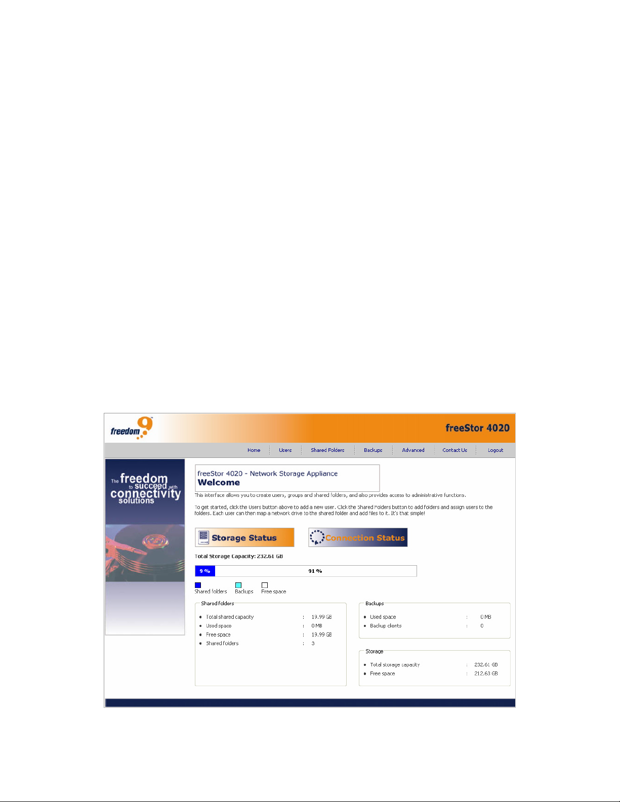
3.2 Home
The Home Page (Figure 3-3) displays summary information about the device. The Storage
Status page displays the space allocated and used for file sharing and backups by the freeStor
4020.
Note: The total storage capacity will be less than the total size of all of the hard
disks because some of the disk space is needed for the operating system and
management software. In addition, the amount of used backup capacity will be
greater than the total size of all the disks listed on the Backups page because
additional storage space is needed for the data that has changed between
backups.
Figure 3-3: Home Page
18
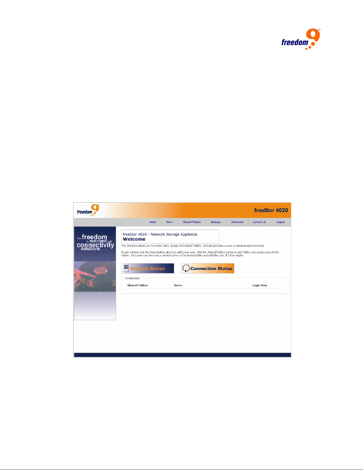
Clicking on the Connection Status button will display a list of users and the shared folders they
are connected to (Figure 3-4). Due to the nature of the NFS protocol, Linux and Mac
connections are not listed on this page. Likewise, ongoing backup or recovery activities do not
appear on this page.
This page indicates only that a connection with a shared folder has been established; this does
not necessarily mean that the user has opened any files in the shared folder.
Notes:
• If a user accesses a shared folder using the “guest” user name, the name
guest appears in the Users column, followed by the user’s computer name in
parentheses.
• Due to the nature of the NFS protocol, Linux and other Mac users are not
listed on this page.
• Ongoing backup or recovery activities do not appear on this page.
• This page indicates only that a connection with a shared folder has been
established; this does not necessarily mean that the user has opened any
files there.
Figure 3-4: Connections Page
19
freeStor 4020 User’s Manual
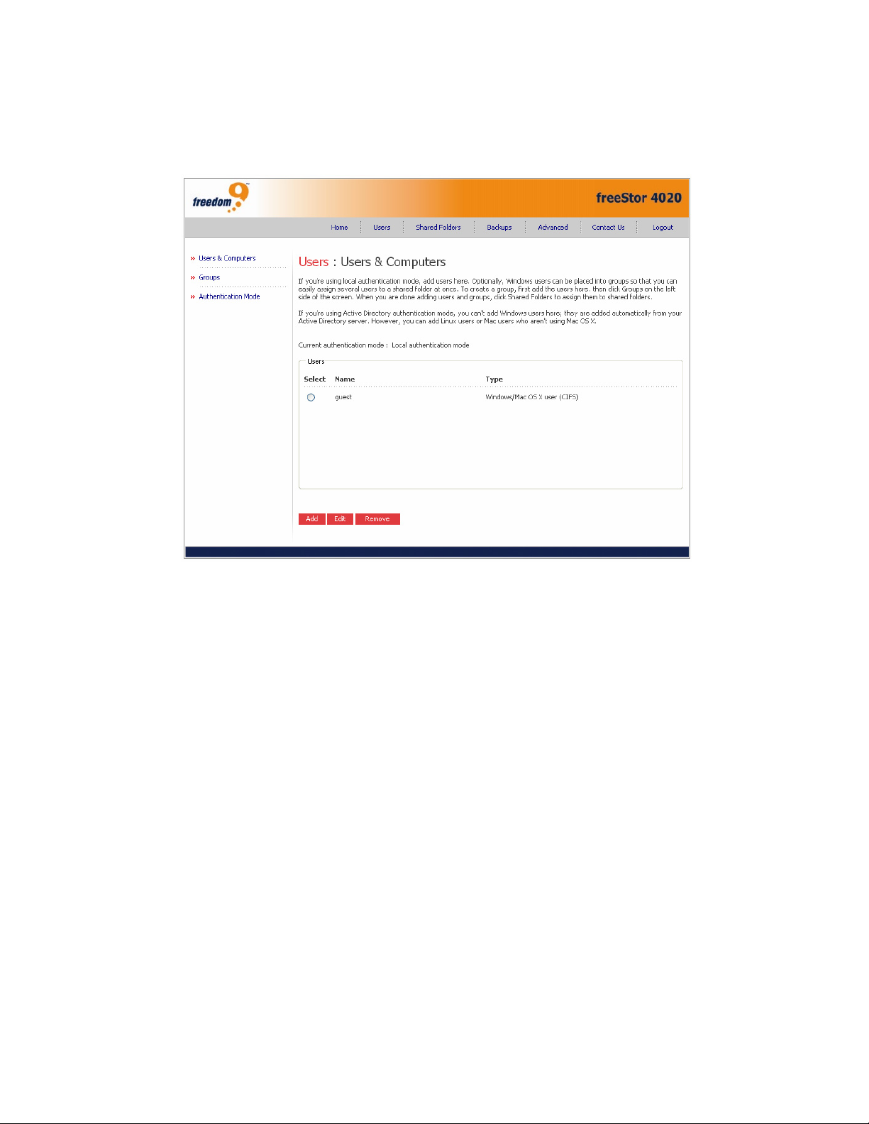
3.3 Users
Clicking on the “Users” button in the menu will open the Users Page (Figure 3-5) which allows
you to manage the users on the freeStor 4020.
Figure 3-5: Users Page
Note: By default, the storage system uses local authentication mode. If your site
uses Active Directory, you might want to use Active Directory authentication
mode instead. Since all user data and all shared folder assignments are deleted
when you switch from one mode to another, it is recommended that you decide
which mode you want to use before proceeding.
In local authentication mode, by default the freeStor 4020 includes a user named “guest” that
has a password of “guest”. Windows and OS X users can access all shared folders that the user
“guest” is authorized to access. However, for increased security, it is advised that additional
users are added as well. For example, to restrict access to a shared folder that contains
confidential information, you would add at least one user and authorize that user to access that
shared folder and not authorize the “guest” user to access it. Adding a user for each individual
or computer in the network provides maximum flexibility and security, enabling you to control
exactly who can access what information.
In addition, only Windows and OS X users can use the “guest” user account. If there are Linux
users or Mac users on the network, you must add users to allow these computers to access any
shared folders.
When you add a Windows or OS X user, a folder with the same name as that person’s user
name is automatically created on the storage system. Only that person can access that folder,
and that person has full read/write access to it. In the Storage System Console, this folder is
identified as the home folder.
You can add up to 128 Windows or Mac OS X users, and up to 128 Linux or other Mac users
(for a total of up to 256 users).
20
Note: Since each Linux or Mac user can represent multiple users, the number of
actual users can be higher.
Adding Users
By default, the storage server uses local authentication mode, which means that you can add,
modify, or remove all types of users at any time. If you’re using Active Directory authentication
mode, you can add, modify, or remove Linux or other Mac users, but not Windows users. All
Windows users are controlled entirely by the Active Directory server.
If you’re using local authentication mode, you can also put Windows and Mac OS X users into
groups. This makes it easier to give several users access to the same shared folder at once. For
example, in an office environment, you might create one group for all users and give that group
read-only access to a shared folder with corporate policies. You might then create separate
groups for each department (such as Sales or HR) and give those groups read/write access to
shared folders with information specifically for those groups (such as expense reports or
company benefits). Each user can be a member of multiple groups. (If you’re using Active
Directory authentication mode, you cannot create groups using the Manager. All groups are
controlled entirely by the Active Directory server.)
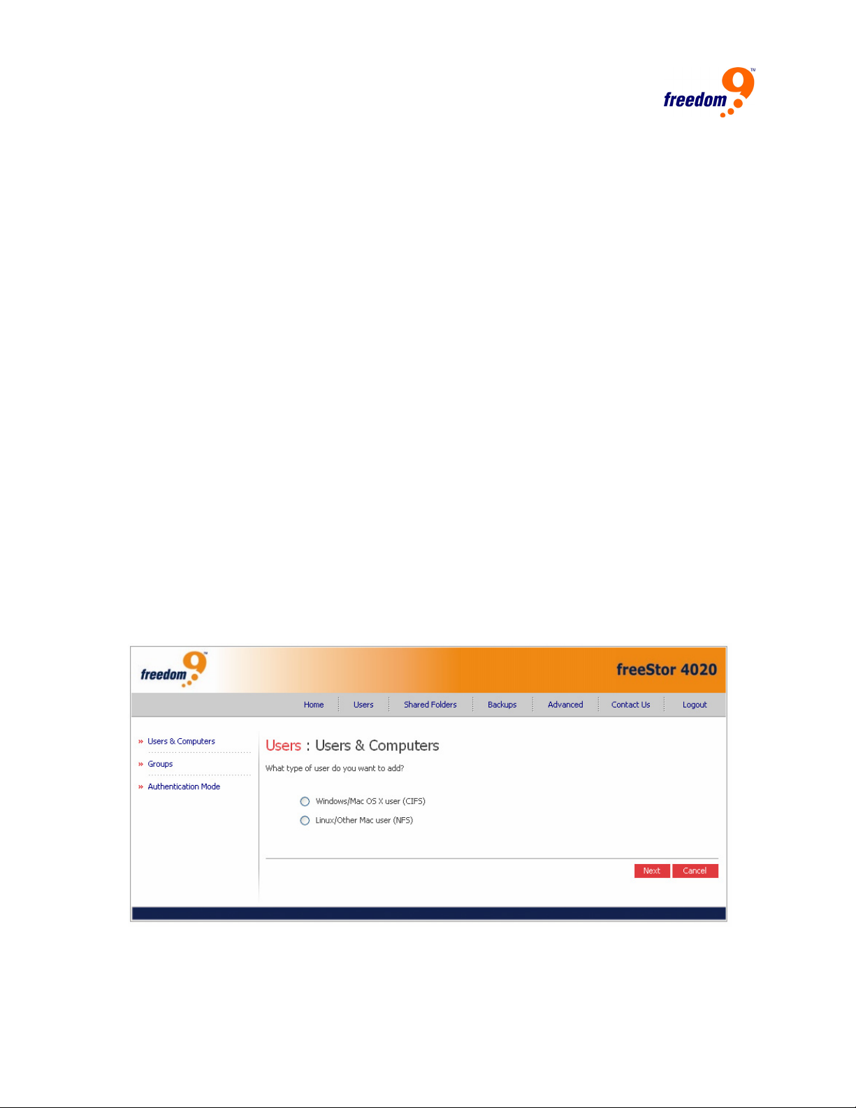
To add a new user:
1. Click “Add” to open the Add User page (Figure 3-6). Select the type of operating system
used by the user and click “Next”.
Note: Linux and Mac users must use Network File System (NFS) to access the
freeStor 4020. Using this protocol, they are given access based on the computer
and not the individual users on the computer. However, in Windows and OS X
environments, each computer user can have individual access to a shared folder.
Note: If Active Directory is being used, only Linux and Mac users can be added
on this page. All Windows users are controlled by the Active Directory server.
Figure 3-6: Add User Page
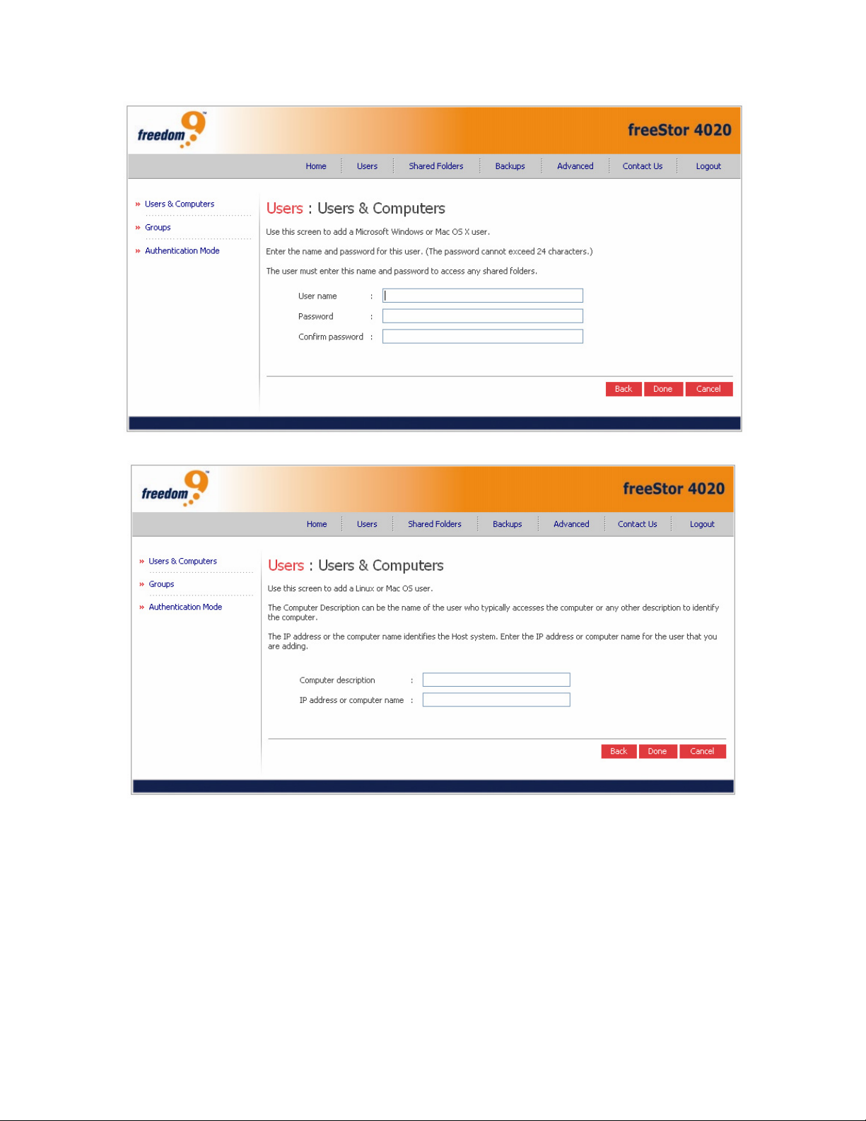
2. The next page that is displayed depends on the type of user being added. For Windows and
OS X users, the page shown in Figure 3-7 will be displayed, and for Linux and Mac users,
the page shown in Figure 3-8 will be displayed.
21
freeStor 4020 User’s Manual
Figure 3-7: CIFS Add User Page
Figure 3-8: NFS Add User Page
3. For Windows and OS X users, enter the user name and password users have to enter to
access their account. Re-enter the password in the last field and click “Done” to continue.
The user name can be up to 20 characters long and can include letters and numbers. It
cannot begin with a period, contain spaces or a double period, or contain the following
characters:
/ \ [ ] : ; | = , + * ? < > @ " ' # ~ ` % $
The password can be up to 24 characters long.
Note: If the user name and password specified here are the same as the
person’s Windows user name and password, the person will not be prompted to
22

provide a user name and password when accessing the shared folder.
4. For Linux and Mac users, enter a description of the computer(s) being used to access the
freeStor 4020. The Computer description can be the name of the person who typically uses
the computer, or any other description that you want to provide to identify the computer in
the Users list. This description can be up to 15 characters long. It cannot contain the
following characters: / \ [ ] : ; | = , + * ? < > @ " '
The IP address or computer name is the IP address or the actual computer name in the
computer's system configuration. The computer name cannot contain spaces or the
following characters: /\ [ ] : ; | = , + * ? < > @ "
Note: You can create a single user account that represents multiple computers.
In the “IP address or computer name” textbox, you can use the wildcard
characters * and ? to represent multiple client machines (e.g. “client*” and
“client?” will match any computer in the subnet with a name starting with “client”.
“*.company.com” would include all computers in the domain “company.com”). The
wildcards can only be used with computer names and not IP addresses.
5. Repeat steps 1 to 4 to add additional users. The user name and type for each user is
displayed on the Users & Computers page.
Modifying Users
In local authentication mode, for Windows and Mac OS X users you can change the password
used to access the shared folders, but not the user name. This change will not affect current
connections, but will take effect the next time the person tries to connect to a shared folder. (In
Active Directory authentication mode, you cannot modify Windows/Mac OS X users, only
Linux/other Mac users.) For Linux and other Mac users, you can change the IP address or
computer name, but not the computer description. Changing this information immediately
disconnects that computer from the shared folders.
Note: To change the user name or computer description, you must remove the
existing user as described in “Removing users” below, and then add a new user
with the desired name or description
To modify an existing user:
1. Click the radio button beside the user to edit and click “Edit”. For Windows and OS X users,
the page shown in Figure 3-7 will be displayed. The password used to access the shared
folders can be changed, but not the user name. This change will not affect current
connections, but will take effect the next time someone tries to connect to a shared folder.
The same restrictions apply to user names and passwords here as when adding a user.
2. For Linux and other Mac users, the page shown in Figure 3-8 will be displayed. The IP
address or computer name can be changed, but not the computer description. Changing this
information immediately disconnects that computer from the shared folders.
Note: If the storage system uses Active Directory authentication mode and you
select a Windows/Mac OS X user, this button displays dimmed.
Removing Users
In local authentication mode, you can remove any user except the guest user. In Active
Directory authentication mode, you can remove any Linux user or any Mac user not running
23
 Loading...