

Freedom APFXST5430BFKDI, APFXST6030BFKDI Installation Instruction
Accessible Bath Tub Replacement Shower
Marketing Materials
Product Sheets
Pricing
STORAGE AND HANDLING OF FOUR PIECE SHOWER UNITS
ACCESSIBLE BATHTUB REPLACEMENT SHOWERS
ATES6030BFKD1.0
APXST6030BFKD1.0
APFXST5430BFKD1 & APFXST6030BFKD1
www.freedomshowers.com
Tools/materials you might need for proper installation
• 6D galvanized screws
• 100% silicone adhesive
• 4- 1.5” x 1.5” x 3” wooden blocks
• shims (provided with the shower)
• tape
STORAGE AND HANDLING OF FOUR PIECE
SHOWER UNITS
1. Most handling damage is the result of impact blows to the
back side of the berglass units.
2. These sectional units are typically unpacked and unbolted
so the separate parts may be moved to the installation area.
Please use caution when unbolting the sections. Carry the
parts with minimal exing to avoid stress cracks. (Measure
and mark supply valve and shower head locations before
unbolting).
Installation Instructions
stored with special care. During storage, this unit should
never sit as it was received. It should be stored with a 2” x
4” block of some other type of material at each of the (4)
points numbered above in the top view. Units having altered
threshold heights do not have wooden bottoms to reinforce
the oors. By placing the unit on blocks, the molded drain
will not rest on the oor. This will allow the draft of the oor
to be maintained without the weight of the shower unit
pushing the drain upward. The blocks should only be placed
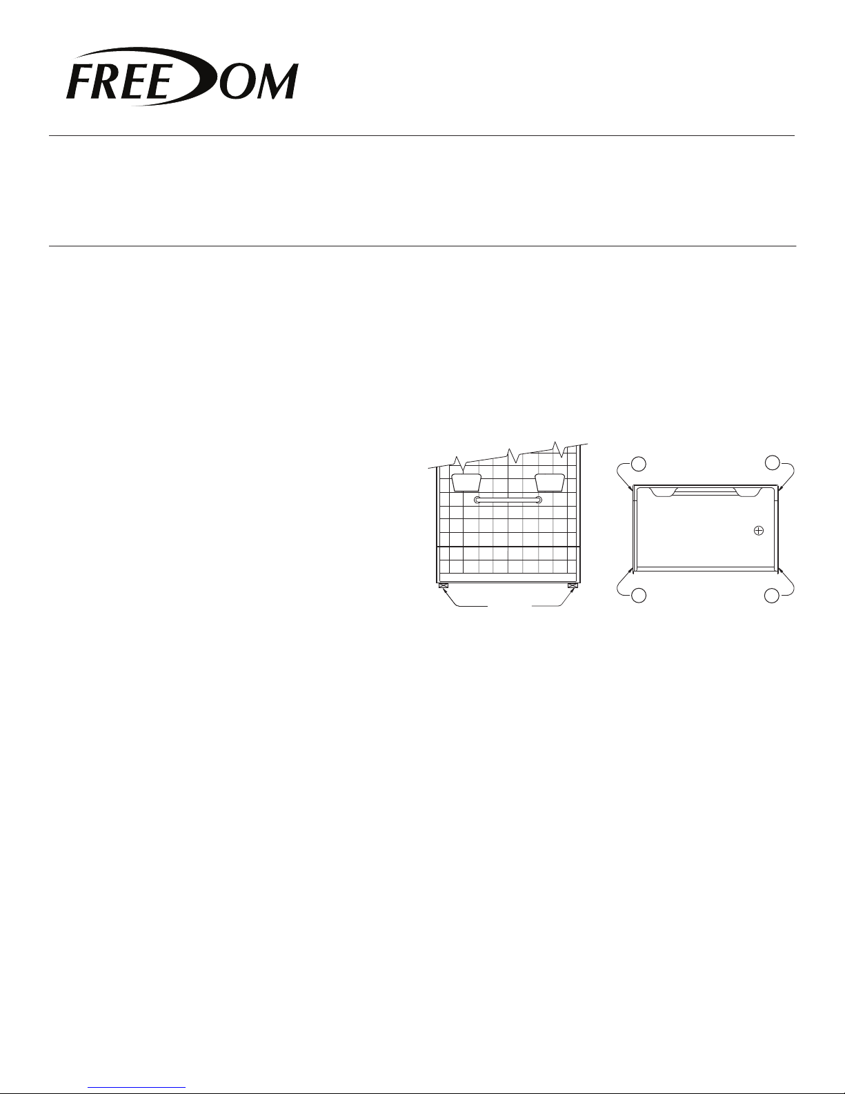
FRONT VIEW
2
TOP VIEW
4
3. Placing objects inside the unit can cause scratches or nicks
to the nished surface. Do not use the shower as a trash
receptacle! Always place a drop cloth or cardboard on the
oor when working inside the shower.
4. Storing units outside right-side up can cause sunlight to
discolor the gelcoat nish. Also, unit becomes unstable and is
easily knocked over by wind or bumping.
5. The back of a berglass unit is not waterproof. Unit must
be stored so water will drain off and not accumulate in one
spot. Water can permeate the back laminates and soak the
glassed in wood or cardboard supports causing bulges in
the gelcoat surface.
6. Never drag a berglass unit on any surface. Always
transport the unit by hand using (2) people or two wheel
dolly.
7 . Never let a berglass unit drop from any height, not even
an inch or stress cracks are likely to occur.
8 . Never clean berglass gelcoat surface with metal tools of
any kind, including razor blades.
VERY IMPORTANT FOR LOW THRESHOLD
SHOWER
The low threshold showers, model numbers:
APFXST5430BFKD1 and APXST6030BFKD1 must be
Proper
Block
Placement
at the outside corner edges of the unit and should not be
placed under the middle of the threshold. This procedure
should only be used during storage and not for installation.
Certain units may ship with a template under them to
prevent the drain from resting on the oor. This template
should remain attached during storage and removed just
before installation.
PLANNING YOUR INSTALLATION
1. Carefully remove the old bathtub at the installation site.
The replacement showers are 82” tall so wall board should
be removed on all three walls to at least this height.
2. The shower unit must be disassembled for installation. All
joints must be caulked as they are installed. When moving
the parts, take care to avoid striking the edges of the wall
sections to prevent chips or cracks.
3. Study framing diagrams. Adjust drain and water supply
locations if required. Cutout in oor for drain requires a
minimum size of 10” x 10”.
1
3

Accessible Bath Tub Replacement Shower
Marketing Materials
Product Sheets
Pricing
www.freedomshowers.com
4. Modify framing if required. There should be a framing
member behind each ange. Make sure your framing is plumb
and square.
5. Planning is necessar y for Tin-Set mortar or 100% silicone
adhesive to be placed in the drain core area for all installations.
Proper blocking is required to prevent the Thin-Set from
owing to the oor below.
Showers congured with the factory installed EasyBase™
self leveling, reinforced bottom will be installed using panel
adhesive. However, wet mud will be used in the drain core
area on these units. See Figure 1.
INSTALLATION INSTRUCTIONS
1. Before you disassemble the shower unit, transfer the
locations for the supply valve and shower head on the unit.
Mark these locations on the back (reinforced surface) of the
unit. After double checking the locations, drill 1/4” pilot holes.
2. Always place cardboard or a drop cloth in the shower base
to protect the nished surface. Working from the nished side
of the unit, using the proper size hole saw, cut holes for supply
lines and shower head.
3. Remove the connection bolts and disassemble the unit. If
present, remove shower rod. Carefully carry the parts to the
installation area. Do not ex the par ts when moving to avoid
scratches and stress cracks.
4. The shower may be reassembled and installed in one piece
if there is sufcient room. Typically, the parts are installed
piece by piece starting with the base. If installing in one
piece, the metal nuts and bolts will be used for permanent
connection. The installer must apply 100% silicone caulking to
all connection surfaces for nal installation.
5. When installing piece by piece, use the pin system in place of
the nuts and bolts. The pins will act as guides that will index the
parts together for installation where access to the back side in
unavailable.
6. Apply a liberal amount of 100% silicone caulk to each pin
before inserting them through the holes.
Insert the plastic fasteners through the holes from below so
they point to the ceiling.
APFXST5430BFKD1 & APFXST6030BFKD1
Installation Instructions
NOTE: The caulking must be allowed to cure before assembly
of the unit.
7. Carefully position the shower base so it sits on the front
mounting anges. Install the drain tting in accordance with
instructions provided with the tting. Do not allow the base
to sit on the drain tting.
8. Review the framing diagram illustrated in Figure 1. The
diagram details the method of installation of the EasyBase
self leveling reinforced bottom. When installing, it is
ESSENTIAL to assure the ENTIRE bottom of the shower
be securely adhered to the building oor. The shower will
not drain properly unless the bottom is properly installed in
accordance with these provided installation instructions.
Review Figure 1 and read these instructions thoroughly
when planning you installation. Failure to install the unit in
accordance to these provided instructions will void the
warranty.
Accessibility Professionals are not responsible for
installations that do not adhere to these provided
instructions.
9. Study framing diagram and note the important
installation requirements.
Note that Thin-Set mortar is used in the DRAIN CORE ONLY.
Fill the drain core only 2/3rds full of Thin-Set. Do not
overll as this will prevent proper oor draft and may push
the drain area up causing the unit not to drain properly.
The shower base is installed separately from the wall
sections. Before applying any Thin-Set or Adhesive, trial t
the shower base to conrm the alcove is of proper size and
the drain is located properly.
10. The ENTIRE bottom is adhered to the Sub-Floor using
3M Polyurethane Construction Adhesive (or equivalent).
This includes the entire bottom minus the drain core.
11. Note in the FRAMING DIAGRAM that construction
adhesive is spread over the entire area where the
EasyBase™ is in contact with the Sub-Floor. This includes the
front threshold area.
12. Before beginning installation, it is ESSENTIAL that the
sub oor in the installation area be completely clean. It
™
 Loading...