

Freedom 458 Series COMBI, COMBI 10, COMBI 15, COMBI 15S/D, COMBI 20 Owner's Manual
...
OWNER’S MANUAL
FREEDOM 458 Series COMBI
INVERTER/CHARGER
Model 10
Model 15, 15 S/D
Model 20, 20 S/D
Model 25 D/D
Model 30, 30 D/D
TM
*Manual includes all models of Freedom 458 Series Combi™ Inverter/Chargers
INFORMATION IN THIS MANUAL IS SUBJECT TO CHANGE WITHOUT NOTICE
®

The statements, specifications and instructions in this
publication are believed to be correct. No warranty is
made, expressed or implied by the seller or manufacturer with respect to any results or lack thereof from
the use of information in this publication and no
liability is assumed for any direct or consequential
damages, personal loss or injury. All statements made
herein are strictly to be used or relied on at the user’s
risk.
© 1999 Heart Interface. All rights reserved.

TABLE OF CONTENTS
Introduction...................................................................... 1
Technical Support ...................................................... 1
Servicing...................................................................... 1
Warranty ..................................................................... 2
Features ....................................................................... 2
DC to AC Power Inverting................................. 2
Automatic Transfer Switching ........................... 2
Automatic 3-Stage Battery Charging ................ 3
Unit Protection ..................................................... 3
Neutral Bonding .................................................. 3
Power Sharing ...................................................... 3
Inverter Idle Circuit............................................. 4
Thermostat Controlled Cooling......................... 4
Remote Controls .............................................................. 5
Remote Control Panel ......................................... 5
LINK Instrument ................................................. 5
Batteries............................................................................. 7
Selecting Batteries ...................................................... 7
Wet Cell Batteries................................................. 7
Gel Cell Batteries.................................................. 8
Advanced AGM Batteries................................... 8
Battery Bank Ratings and Sizing ............................. 8
Battery Discharge/Charge Cycling................... 9
Calculating Your Amp-Hour Usage
Between Battery Recharges ................................ 9
Typical Power Consumption.................................. 10
Connecting Batteries ............................................... 12
Connecting Batteries in Series.......................... 13
Connecting Batteries in Parallel....................... 14
Connecting Battery Banks ................................ 15
Installation ...................................................................... 16
Before You Install Your
Freedom Inverter/Charger .................................... 16
Installing the Freedom Inverter/Charger............ 17
Step 1: Mount the Freedom
Inverter/Charger ............................................... 18
Step 2: Connect the AC wiring......................... 19
Step 3: Install ground fault
circuit interrupters............................................. 23
Step 4: Connect the battery cables ................... 23
Step 5: Install battery cable fuses..................... 26

Step 6: Install the optional Remote Control
Panel or LINK instrument ................................ 28
Step 7: Install the Temperature Sensitive
Charging (TSC) sensor, if you are using it ..... 29
Step 8: Check over your unit
to make sure it is properly installed ............... 29
Installation Examples .................................................... 33
Installation Configurations .................................... 33
Installation Option 1 for
Freedom 10, 15, 20, 25 D/D, 30, and 30 D/D ...... 38
Installation Option 2 for
Freedom 10, 15, 20, 25 D/D, 30, and 30 D/D ...... 40
Installation Option 3 for
Freedom 25 D/D and 30 D/D ............................... 43
Installation Option 4 for
Freedom 25 D/D and 30 D/D ............................... 46
Installation Option 5 for
Freedom 15 S/D and 20 S/D ................................. 49
Operation ........................................................................ 51
Selecting the Battery Type ...................................... 52
Reading the Status LEDs ........................................ 53
Troubleshooting LED Status .................................. 54
Power Inverting ............................................................. 56
Turning the Inverter On and Off ........................... 56
Battery Shutdown .................................................... 57
Battery Charging............................................................ 58
Turning the Charger On and Off ........................... 58
Automatic 3-Stage Battery Charging .................... 58
Optional Equalizing Charge .................................. 64
Temperature Sensitive Charging (TSC) ................ 66
Replacing Battery Cable Fuses..................................... 66
Resetting Circuit Breakers ............................................ 67
Specifications.................................................................. 68

Introduction
INTRODUCTION
Thank you for purchasing a Heart Interface Freedom 458
Series Combi
in manufacturing quality products specifically designed to
meet your power requirements.
Freedom Inverter/Chargers provide silent, efficient and
reliable AC power for a variety of applications. They feature
“hands-free” operation, automatic 3-stage battery charging
and automatic AC transfer switching. For your convenience,
service is available worldwide by qualified service centers.
Technical Support
If you have any questions about your Freedom Inverter/
Charger, please contact Heart Interface toll-free in the U.S. and
Canada, at (800) 446-6180 (outside 253 area code) or at
(253) 872-7225.
For technical support and additional information about Heart
Interface products, visit our web site at
www.heartinterface.com or send us e-mail at:
Inverter/Charger. Heart Interface takes pride
TM
• techhelp@heartinterface.com
• sales@heartinterface.com
Servicing
Qualified service personnel should perform all servicing of
your Freedom Inverter/Charger.
Caution
• Risk of electrical shock.
• Do not open this unit. There are no user serviceable parts inside.
• Both AC & DC voltage sources are terminated inside this
equipment. Disconnect all inputs and outputs before servicing.
1

Introduction
Warranty
Your Heart Interface Freedom 458 Series CombiTM Inverter/
Charger has a 30-month limited warranty, from date of purchase.
Terms of this warranty are detailed on the warranty registration card. Please complete this card and return it to Heart
Interface. Returning the card will register your warranty.
If your unit requires service, phone Heart Interface at the
number listed below. Please have the model number, and
serial number ready for the service technician. You can find
these numbers on the unit’s mounting flange or on the
manual’s front cover. The model number will look like “81-
XXXX-12.”
Phone numbers: (253) 872-7225
Toll-free in U.S. and Canada,
outside 253 area code (800) 446-6180
Features
The service technician will issue a return authorization number for all returns. All returns must have a return authoriza-
tion number.
Ship the unit freight prepaid, to Heart Interface or to the field
service center. Write the return authorization number on the
outside of the packaging.
DC to AC Power Inverting
Your Freedom Inverter/Charger provides 120-volt, AC power
to run your appliances from deep cycle DC batteries.
Automatic Transfer Switching
The Freedom Inverter/Charger automatically switches between inverter power and incoming AC power. The unit can
use external AC as its power source in addition to batteries.
The internal transfer switch allows the unit to transfer the AC
power through directly to the loads.
2

Introduction
When the external AC power source is disconnected, the
transfer switch allows automatic switching back to the inverter.
Automatic 3-Stage Battery Charging
The Freedom Inverter/Charger is designed to rapidly and
optimally charge wet, gel, or Absorbed Glass Mat cell deepcycle batteries. The battery charger automatically proceeds
through the bulk, acceptance, and float charging stages,
resulting in an efficient, complete charge.
Additionally, you can use Remote Control Panel or the LINK
instrument to manually equalize wet cell batteries. Equalizing
restores your wet cell batteries to their optimal, operating
condition.
Unit Protection
Fast-acting electronic circuits protect your Freedom Inverter/
Charger from overloads and short circuits. Your unit also has
low and high battery voltage cutoff, and automatic shutdown
if it gets too hot.
Neutral Bonding
The Freedom Inverter/Charger automatically bonds the
internal AC output neutral (white) to the internal AC output
ground (green), when the unit is off or in the inverter mode.
No additional wiring is needed for this process.
When incoming AC power is applied and the transfer switch
engages, and the internal neutral-to-ground bond is automatically lifted.
This insures safety in all conditions and meets the National
Electrical Code (NEC) requirements.
Power Sharing
When the unit is connected to an external AC source, the
battery charger and transfer functions are engaged. A unique
Power Sharing feature automatically reduces the AC power
consumption of the battery charger. This allows the necessary
3

Introduction
AC power to go to the loads and helps to prevent the source
AC input circuit breaker from tripping.
The Power Sharing set point is set to factory default of 30
amps. This can be changed using the Remote Control Panel or
LINK instrument.
Inverter Idle Circuit
This automatic, energy saving feature reduces battery power
consumption when you do not have an AC load connected to
the Freedom Inverter/Charger’s output. You can use the
Remote Control Panel or LINK instrument to adjust the idle
threshold. The factory default setting is 5 watts.
To bring the unit out of the idle condition, apply a load.
Response from idle is instantaneous.
Thermostat Controlled Cooling
Your Freedom Inverter/Charger is equipped with a thermostatically controlled fan. This cools the unit so it can operate
continually at its rated output.
4
Remote Controls
REMOTE CONTROLS
You can purchase two types of Heart Interface remote controls
to use with your Freedom Inverter/Charger:
1. Remote Control Panel
2. LINK instruments
Installation and operations instructions for your remote
control are packed with the panel.
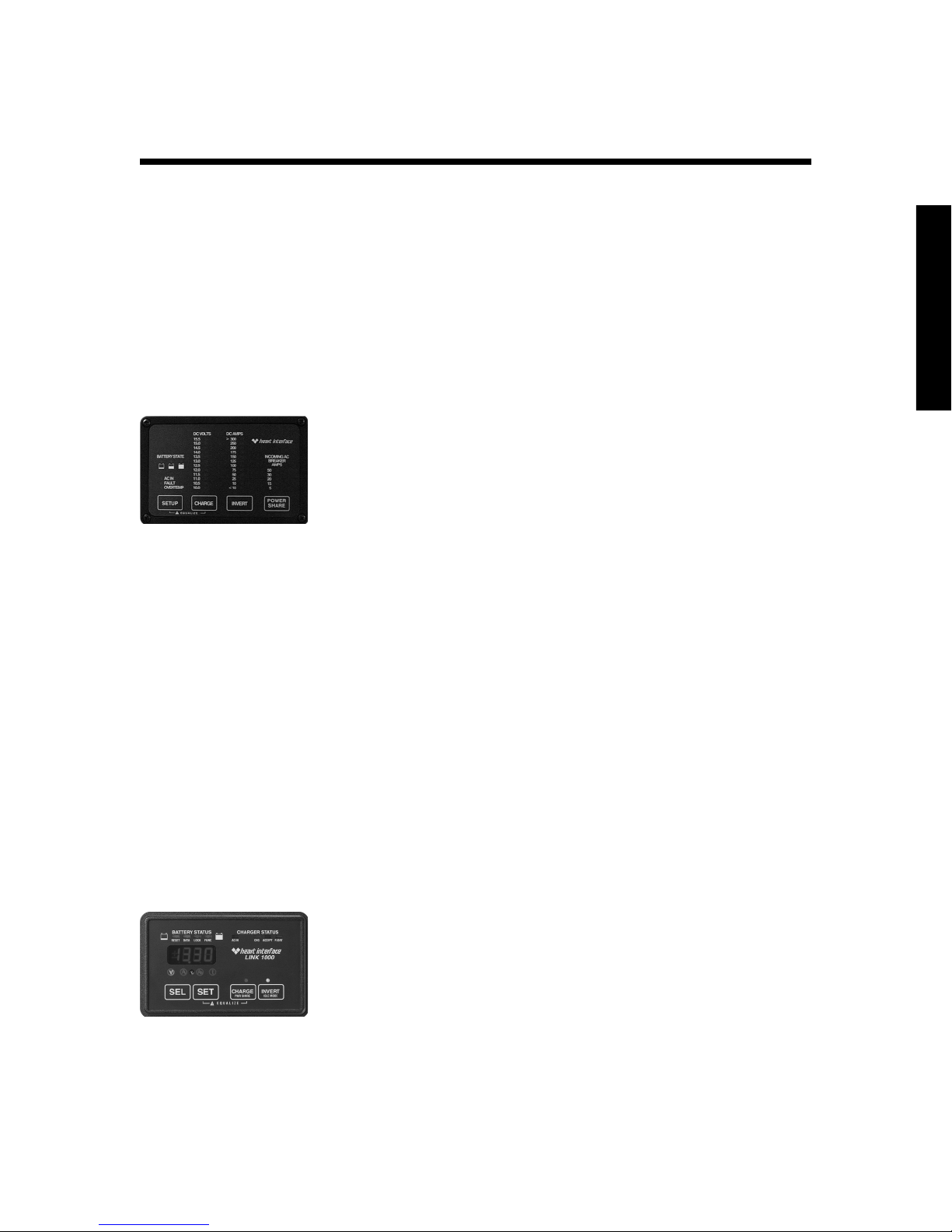
Remote Control Panel
The remote control panel has:
• LED bar graphs to show you the battery voltage and DC
current in both inverter and charger modes.
• Easy to see red, yellow and green LEDs to show you the
state of the battery charge.
• Controls for charger ON/OFF, inverter ON/OFF and
Power Sharing.
• Set up features includes selection of Idle Threshold, Battery Type and Battery Capacity.
LINK Instrument
Heart Interface offers three advanced remote control panels:
LINK 1000, LINK 2000, and LINK 2000R. All LINK instruments provide:
• State of the battery charge information. This includes the
DC voltage, current, amp-hours consumed, how much
time remains on the batteries and historical data.
• Freedom Inverter/Charger controls
LINK 1000
The LINK 1000 provides information and controls for a single
battery bank. It also measures the voltage of an auxiliary
battery.
5

Remote Controls
LINK 2000
The LINK 2000 monitors two battery banks.
LINK 2000R
The LINK 2000R adds the ability to regulate an engine-driven
alternator. The precision regulator in the LINK 2000R allows
the alternator to be controlled as a 3-stage battery charging
system.
6

Batteries
BATTERIES
Selecting Batteries
When you choose your batteries, look for true, deep cycle
batteries that are rated in amp-hours (AH) and sized to match
your power requirements. Use the “Typical Power Consumption” chart on page 10 to help you calculate how many batteries you need to purchase. Check with your battery manufacturer for the specifications.
Deep-cycle batteries fall into three broad categories: wet cell,
gel cell and advanced AGM (Absorbed Glass Mat) batteries.
Wet Cell Batteries
True deep-cycle wet cell batteries have relatively thick internal
plates that are alloyed with antimony. Look for the following
types:
• 12-volt marine/RV deep-cycle batteries are acceptable.
• 6-volt golf cart batteries perform well and may have a
longer life. These batteries must be used in series and
connected in pairs.
• High quality deep-cycle batteries offer good performance
and are available in a wide variety of sizes.
Types of Wet Cell Batteries to Avoid
• Do not use ordinary car batteries or engine starting
batteries. If the battery is rated only in Cold Cranking
Amps (CCA) and reserve capacity, it is designed to start an
engine.
• Most hybrid type, wet cell batteries will have limited life
if deeply discharged. These batteries are described as
suitable for either engine starting or deep-cycle applications.
• Do not use maintenance-free, wet cell batteries. They will
not hold up well to deep discharging and repeated cycling.
Wet Cell Battery Maintenance
• Frequently check the electrolyte level in wet cell batter-
ies. These batteries will give off gas as a natural result of
charging; therefore they will lose water. When necessary,
7

you should add distilled water. Follow the battery
manufacturer’s recommendations for maintenance.
• Never allow the tops of the battery plates to be exposed to
air. This will contaminate the battery cells. When necessary, add distilled water to the battery.
• Keep the battery tops and terminals clean.
• Always provide adequate ventilation in the battery storage
compartment.
Gel Cell Batteries
Gel cell batteries are sealed, lead-acid batteries. They have the
following features:
• No Maintenance
Batteries
• Low Self-Discharge Rate
• Low Internal Resistance
Even though gel cells are sealed batteries, you should ventilate
the battery compartment.
Advanced AGM Batteries
AGM batteries are sealed, lead acid batteries. They are similar
to gel cell batteries. The charging parameters are similar to wet
cell batteries.
Battery Bank Ratings and Sizing
Deep-cycle batteries are rated in amp-hours. The amp-hour
rating is based on a 20-hour discharge rate; therefore, a 100
amp-hour battery can deliver 5 amps for 20 hours.
When the discharge rate is greater than 5 amps, the available
amp-hours are decreased. As the discharge rate increases, the
effective battery capacity is reduced. For example, if the
discharge rate is increased to 100 amps, the battery can deliver
about 45 amp-hours.
8

Batteries
Battery Discharge/Charge Cycling
Deep-cycle batteries can be discharged about 80% of capacity
before damage occurs. Shallow cycling will result in a longer
battery life. A 50% discharge cycle is generally considered to
be a good compromise between long battery life and battery
bank size. To achieve 50% cycling, you should calculate your
amp-hour consumption between charging cycles and use a
battery bank with twice that capacity.
Calculating Your Amp-Hour Usage Between
Battery Recharges
1. Find the amp-hour usage for each AC appliance or tool
that will draw its power from the inverter by:
• Figuring out how long you plan on using each appli-
ance between battery recharges.
• Finding the appliance in the “Typical Power Consump-
tion” chart, on page 10.
• Reading across the row, until you find the amp-hour
usage in the appropriate column.
2. If your AC appliance or tool is not listed in the “Typical
Power Consumption” chart, calculate its power usage by:
• Looking for the rating plate on the appliance or tool. It
will be rated in AC Amps, Watts, or AC VA (VoltAmps) apparent power.
• Using one of the formulas in the “Amp-Hour Con-
sumption Formulas” chart to calculate the DC amphour draw on a 12-volt system.
3. Add up the amp-hour usage figures for all the appliances
or tools. This gives you the total amp-hour load requirement.
4. Your battery bank should be a minimum of 2 times larger
than the total amp-hour load requirement. You should
plan on recharging your batteries when they are 50%
discharged.
9

Batteries
Amp-Hour Consumption Formulas
(AC Amps x 10) x 1.1** x Hours of Operation = DC Amp-Hours
(AC Watts/DC Voltage*) x 1.1** x Hours of Operation = DC Amp-Hours
(AC Volt-Amps/DC Voltage*) x 1.1** x Hours of Operation = DC Amp-Hours
*DC Voltage is 12, 24 or 32 volts, depending on your system.
**1.1 is the inverter-efficiency correction factor.
Typical Power Consumption
The chart identifies typical power consumption for common
AC loads. Use it as a guide when identifying your power
requirements.
Many electric motors have momentary starting requirements
well above their operational rating. Start-up watts are listed
where appropriate. Individual styles and brands of appliances
may vary.
Note: The output power is a modified sine wave. Certain laser
printers, bread-makers, dimmer lights, variable speed tools,
digital clocks and appliance/tool chargers may not operate on
the inverter’s output power.
10

Batteries
Typical Power Consumption
semiTnuRecnailppAsuounitnoC
ecnailppA
lacipyT
egattaW
5
51
.niM
03
.niM
.niM
.rH1.rH2.rH3.rH8.rH42
sruoH-pmACD,tloV-21ni
VTroloC"310533.01248212369
VTroloC"9100166.0248614246291
RCV0533.01248212369
pmaL00166.0248614246291
rednelB0032621
potpaL
retupmoC
0533.01248
norIgnilruC0533.012
llirDrewoP"8/30053.30102
*rekamecI0026.22.54.016.516.142.38
rekaMeeffoC00016.6020408061
.tf.uc3
*rotaregirfeR
.tf.uc02
*rotaregirfeR
tcapmoC
evaworciM
eziSlluF
evaworciM
051248212369
057122448621633276
0575510306021081
0051010306021042063
muucaV00113.7224488671462
*Refrigeration is typically calculated using a 1/3-duty cycle.
11

Batteries
Connecting Batteries
In most cases, you will be using a bank of two or more batteries with your Freedom Inverter/Charger. Depending on your
batteries’ voltage, you may connect batteries:
• In series to increase the battery bank’s voltage
• In parallel to increase the battery bank’s amp-hour capac-
ity
You should increase the voltage of a battery bank connected in
series until it matches your system’s voltage. Your battery
bank’s final DC voltage depends on your system. It should be
12, 24 or 32 volts.
Then you should connect the batteries in parallel to increase
the available amp-hours.
Installation Notes
• Always use properly sized wire and terminals for the
interconnecting battery cables. The cables must be, at a
minimum, the same AWG as those connected to the inverter/charger. For size information, refer to National
Electrical Code (NEC) requirements or contact your local
electrician. See “Selecting battery cables” on page 24 for
more information.
12
• Only similar batteries should be connected together in one
bank. Do not connect wet cell, gel cell or AGM batteries
together.
• Do not connect batteries with different case sizes or amphour ratings in the same battery bank.
• Do not connect old and new batteries together.
• Use hex nuts and lock washers on the battery terminals. If
your battery comes with wing nuts, replace them with hex
nuts.
Batteries
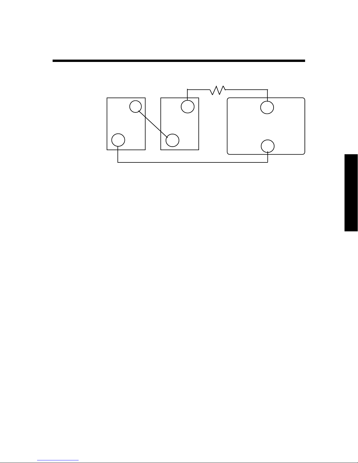
Connecting Batteries in Series
Step 3
Step 1
+
6V 6V
_
Step 3
_
+
Fuse
+
12V INVERTER
_
Step 2
Each battery capacity:
220 amp-hours
@ 6 volts DC
When you connect two batteries in series, you will double the
voltage of the battery bank. The amp-hour capacity of the
battery bank will be the same as the amp-hour capacity of
each individual battery.
For example, two 6-volt, 220 amp-hour batteries connected in
series will produce one 12-volt, 220 amp-hour battery bank.
Total battery bank
capacity:
220 amp-hours
@ 12 volts DC
To connect batteries in series
1. Attach the battery cable to the first battery’s positive (+)
terminal.
2. Attach the other end of the battery cable to the second
battery’s negative (-) terminal.
3. To connect the battery bank to the Freedom Inverter/
Charger, see Installation “Step 4: Connect the battery
cables” on page 23.
13
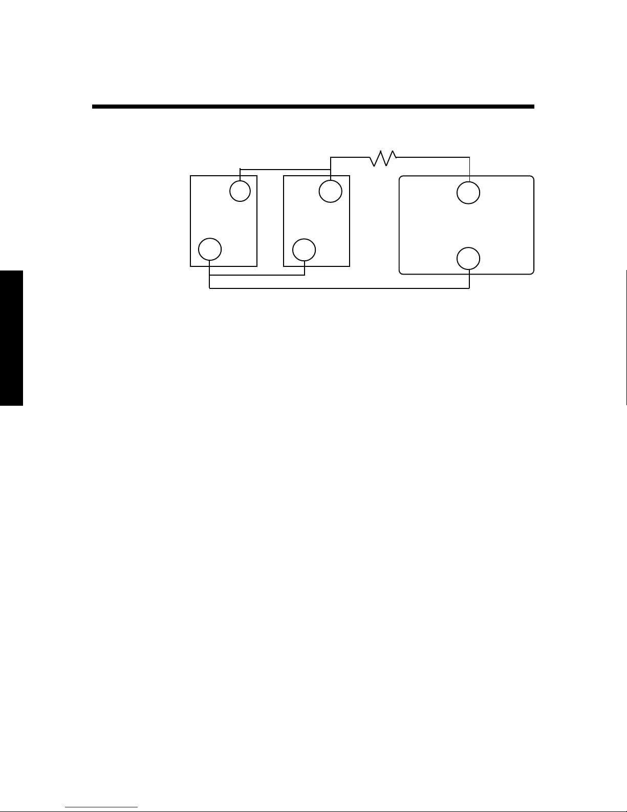
Connecting Batteries in Parallel
Batteries
Step 3
+
12V 12V
_
Step 1 Step 2
Each battery capacity:
105 amp-hours
@ 12 volts DC
When you connect two batteries in parallel, you will double
the amp-hour rating of the battery bank. The bank’s voltage
will be the same as each individual battery’s voltage.
For example, two 12-volt, 105 amp-hour batteries in parallel
will produce one 12-volt, 210 amp-hour battery bank.
To connect batteries in parallel
Step 4
_
+
Fuse
Step 5
Step 5
12V INVERTER
Total battery bank capacity:
210 amp-hours
@ 12 volts DC
+
_
14
1. Attach the negative (-) battery cable to the first battery’s
negative (-) terminal.
2. Attach the other end of the battery cable to the second
battery’s negative (-) terminal.
3. Attach the positive (+) battery cable to the first battery’s
positive (+) terminal.
4. Attach the other end of the battery cable to the second
battery’s positive (+) terminal.
5. To connect the battery bank to the Freedom Inverter/
Charger, see Installation “Step 4: Connect the battery
cables” on page 23.
Note: The load is cross-connected in the drawing, i.e., it is
connected to the positive terminal of the first battery and
the negative terminal of the last battery. This helps to
balance the battery bank.
Batteries
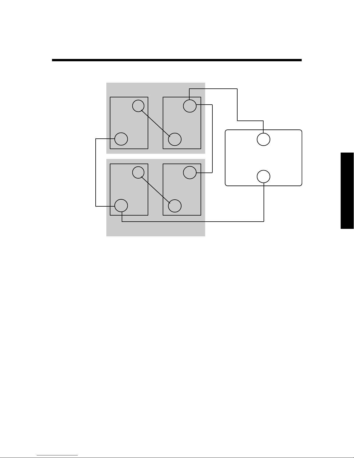
Connecting Battery Banks
Each battery
capacity:
220 amp-hours
@ 6 volts DC
Each series battery
bank capacity:
220 amp-hours
@ 12 volts DC
First battery bank
+
6V 6V
_
Step 1
+
6V 6V
_
Step 2
Second battery bank
When your battery bank is connected in series, and you need
to increase the available amp-hours, you can connect two or
more battery banks together in parallel. This forms a series/
parallel battery bank.
+
Step 3
_
+
Step 4
_
Step 5
Total battery bank
capacity:
440 amp-hours
@ 12 volts DC
+
12V INVERTER
_
Step 5
To connect battery banks in parallel
1. Attach the negative (-) battery cable to the first battery
bank’s empty negative (-) terminal.
2. Attach the other end of the battery cable to the second
battery bank’s empty negative (-) terminal.
3. Attach the positive (+) battery cable to the first battery
bank’s empty positive (+) terminal.
4. Attach the other end of the battery cable to the second
battery bank’s empty positive (+) terminal.
5. To connect the battery bank to the Freedom Inverter/
Charger, see Installation “Step 4: Connect the battery
cables” on page 23.
Note: The load is cross-connected in the drawing. This
helps to balance the battery bank.
15

INSTALLATION
Confirm that your shipping carton contains:
We recommend that an authorized Heart Interface technical
dealer or experienced electrician install your Freedom Inverter/Charger.
Consult the NEC and your local electrical codes for electrical
wiring specifications.
• Inverter/charger
• Owners manual (this manual)
• Warranty card
• TSC temperature sensor with 15’ cable
• Wire nuts
• Two battery terminal covers, one red and one black
Installation
Before You Install Your Freedom Inverter/Charger
Gather the following supplies:
• Fuse—UL Listed, DC Rated slow blow class “T” fuse as
required by NEC. See “Recommended Fuses” chart on
page 27.
• 10-gauge electrical wire for AC input wiring.
• Electrical wire for AC output wiring. Select the correct
gauge for your Freedom Inverter/Charger model, and
type of installation. Consult the NEC for further information.
• Battery Cables: one negative (-) cable, one short positive
(+) cable (maximum 18”) and one longer positive (+) cable.
Consult NEC for proper cable size. See “Selecting Battery
Cables” on page 24.
• Four mounting screws or 1/4” bolts.
16

Installation
Purchase the batteries:
1. Determine your power usage. Refer to “Typical Power
Consumption” on page 10.
2. Determine which type of batteries you want to buy.
3. Buy sufficient batteries to meet your power usage needs.
Gather the following tools:
• Flathead and Phillips screwdrivers
• 3/16” Allen (Hex) wrench
• 9/16” wrench
• Wire cutters
• Wire strippers
• Wire ties and connectors
• Hand help voltmeter
Installing the Freedom Inverter/Charger
Determine the appropriate installation for your model and
your intended usage by referring to the “Installation Examples” on pages 33-50 before you install your Freedom
Inverter/Charger.
To install your unit follow the steps listed below. Each step is
covered in detail in the following sections.
1. Mount the Freedom Inverter/Charger:
• Determine where to mount the unit
• Place the unit in your selected location.
• Bolt it down.
3. Connect the AC wiring:
• Connect the AC input wiring
• Connect the AC output wiring
• Connect the grounding wires
4. Install ground fault circuit interrupter (GFCI).
5. Connect the battery cables.
17
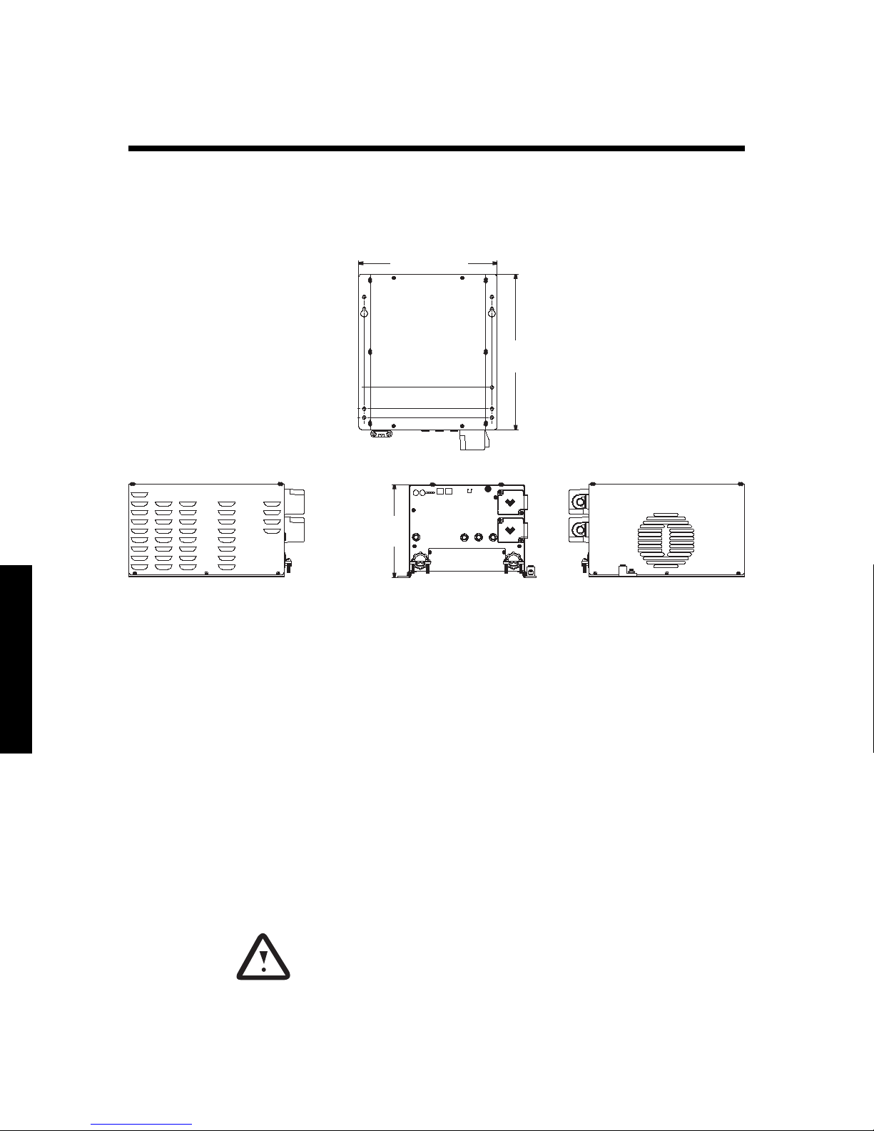
Freedom Inverter/Charger Views
Top View
11.50in
292.10mm
12.88in
327.15mm
Front VIewLeft Side VIew Right Side VIew
7.88in
200.15mm
Installation
6. Install the battery cable fuses.
7. Install the optional remote control panel.
8. Install the Temperature Sensitive Charging (TSC) sensor, if
you are using it.
9. Check over your unit to make sure it is properly installed.
Make sure all wiring conforms to local and national electrical codes. If in doubt, consult a qualified electrician.
Step 1: Mount the Freedom Inverter/Charger
Determine where to mount the unit
Follow these guidelines when you determine where to mount
the unit:
1. Do not install the unit in:
• Enclosed battery compartment.
• Unvented compartment with batteries or flammable
gasses.
18

Installation
• Areas which require ignition-protected equipment.
2. Mount the unit as close to the battery bank as possible.
The overall length of each battery cable should be less than
10 feet.
3. Make sure the unit is not in the presence of flammable
fumes.
4. Mount the unit horizontally (i.e., place on a shelf).
5. Allow several inches of clearance around the unit. This
allows fresh air to reach the cooling fan.
6. Do not block any of the vents or louvers.
7. Make sure that the unit will stay dry and clean.
Install the unit
1. Place the unit in your selected location.
2. Bolt it down. Make sure that it is securely mounted.
Step 2: Connect the AC wiring
Wiring Notes
1. Use appropriate wire gauges throughout the installation.
Refer to NEC regulations.
2. Conventional metal strain reliefs are provided. These can
be replaced with plastic strain reliefs for additional corrosion resistance or with 3/4 inch conduit fittings if you are
using conduit to route the wiring.
3. Do not turn the inverter on until all AC and DC connections (input, output and ground) have been made.
Connect the AC input wiring
1. Check to see that each AC input is protected by a branch
rated circuit breaker.
• In the United States, if a 20-amp breaker protects each
service to the inverter/charger, no additional circuit
breakers are required between the unit and the loads.
• In Canada, a 15-amp breaker must protect each input.
19
 Loading...