


SDX-560V/P
SDX-560V/RP
5.25”Model
Product Specification Manual
Version 1.0
Dec. 2004
Copyright © 2004, Sony Corporation.
All right reserved.
NOTE:
This Product Specification Manual is applicable for AIT-2 Turbo ATAPI I/F drive.

Notice
This document contains proprietary information which is protected by copyright. All rights reserved. No part of this
document may be photocopied, reproduced or translated to another language without prior written consent of
Sony. The information contained in this document is subject to change without notice.
SONY MAKES NO WARRANTY OF ANY KIND WITH REGARD TO THIS DOCUMENT. Sony shall not be liable
for errors contained herein, or indirect, special, incidental or consequential damages in connection with the
furnishing, performance, or use of this document.
© Copyright 2004, by Sony Corporation
For further information , please contact the appropriate Sony location listed below;
Sony Corporation
Electronic Devices Marketing Group
Tape Streamer Marketing Section
Gate City Osaki West Tower
Osaki East Tec.
1-11-1 Osaki Shinagawa-ku, Tokyo, 141-0032 Japan
TEL: (81) 3-5435-3486 FAX: (81) 3-5435-3565
Sony Electronics Inc.
3300 Zanker Road, San Jose, California 95134,
U.S.A.
TEL: (1) 408-432-1600 FAX: (1) 408-955-5533
TLX: 171331 SJESONY
Sony Europe Semiconductor &
Electronic Solutions
The Heights, Blookland, Weybridge, Surrey KT13
OXW
TEL: (01932) 81-6000 FAX: (01932) 81-7001
Sony of Canada Ltd.
Communications & Information Systems Group
Storage Marketing
115 Gordon Baker Road
Toronto, Ontario M2H 3R6
TEL: (416) 499-1414 FAX: (416) 495-3331
Sony Electronics Singapore Pte Ltd
Electronic Devices Marketing (Singapore)
Computer Peripherals Division Enterprise
Storage Solutions Department
2 International Business Park #01-10
Tower One The Strategy Singapore 609930
TEL: +65 6544 7322 FAX: +65 6544 7392
Sony Korea Corporation.
34F, ASEM Tower, World Trade Center, 159-1
Samsung-Dong, Kangnam-Ku, Seoul, 135-798 Korea
TEL: 82-2-6001-4249
Sony Taiwan Limited, ODS Dept. DS Sect.
5F, 145 Changchun Road, Taipei 104, Taiwan
TEL: (886) 2-2522-7953 FAX: (886) 2-2522-2237
Sony Corp. of Hong Kong Ltd. Beijing Rep. Office
Electronic Device Marketing Hong Kong, Computer
Peripheral Division
Tower A, 11/F Full Link Plaza, No.18
Chaoyangmenwai Ave., Beijing, 100020 P.R.C.
TEL: 86-10-6588-0633 FAX: 86-10-6588-0855
Sony Recording Media & Energy Latin America
Storage Drive Group
5201 Blue Lagoon Drive Suite 390
Miami, FL 33126, U.S.A.
TEL: (1) 305-260-4027 FAX: (1) 305-260-7850
Sony Brasil Ltda.
Informatica Division
Rua Inocencio Tobias, 125-Bloco A 01144-000
Sao Paulo, SP Brazil
TEL: (55) 11-3613-9140 FAX: (55) 11-9158-8200

Changing List
Page Clause Title Modify Add Delete Remarks
SDX-560V Series Ver. 1.0 DECEMBER, 2004 (RELEASE)

This page intentionally left blank.

Table of Contents
1. Introducin 1-1
1.1. About This Product Specification Manual 1-1
1.2. Introducing the Sony AIT Technology 1-1
1.3. Features of the Drive 1-1
1.4. Reference 1-2
1.4.1. How to get ECMA-222, 246, 291, 292 Standard Document 1-2
2. Specifications 2-1
2.1. Specifications 2-1
2.1.1. Dimensions 2-1
2.1.1.1. Mounting Holes 2-2
2.1.2. Weight 2-4
2.1.3. Connectors 2-4
2.1.3.1. IDE Cables 2-4
2.2. Environmental Specifications 2-4
2.2.1. Temperature and Humidity Range 2-4
2.2.2. Altitude 2-4
2.2.3. Suspended Particulate 2-5
2.2.4. Vibration 2-5
2.2.5. Shock 2-5
2.2.6. Acoustic Noise 2-5
2.2.7. ESD 2-5
2.2.8. EMI 2-5
2.2.9. Orientation 2-6
2.3. Performance Specification 2-6
2.3.1. Data Capacity 2-7
2.3.2. Data transfer Rate 2-7
2.3.2.1. Sustained Data Transfer Rate to and from Tape 2-7
2.3.2.2. Burst Transfer Rate to and from the IDE Bus 2-7
2.3.3. Initialize Time 2-7
2.3.4. Load Time 2-8
2.3.5. Unload Time 2-8
2.3.6. Search Time 2-8
2.3.7. Rewind Time 2-8
2.3.8. Error Rate 2-8
2.3.9. Retry Limits on Rewrites 2-8
2.3.10. Definition of Failure 2-8
2.3.11. Mean Time Between Failures 2-9
2.3.12. Mean Time to Repair 2-9
2.3.13. Component Life 2-9
2.3.14. Durability 2-9
2.4. Safety 2-9
2.4.1. Conditions of Acceptability 2-9
2.5. Installation Requirements 2-9
2.5.1. Power Requirements 2-10
2.6. Data Compression 2-10
3. Installation 3-1
3.1. Installation Guide 3-1
3.1.1. Data Compression ON Switch 3-2
3.1.2. Power Connector 3-2
3.1.3. IDE Interface Connector 3-2
3.1.4. Jumper Connector 3-3
3.1.5. Attaching and Removing the Dust Cover 3-4
3.1.5.1. Attaching the Dust Cover 3-4
3.1.5.2. Removing the Dust Cover 3-5
SDX-560V series Ver.1.0 Table of Contents

4. Operation 4-1
4.1. Summary of LED Indications 4-1
4.2. Operator Action 4-2
4.2.1. Powering Up the SDX-560V 4-2
4.2.2. Inserting Cassettes 4-2
4.2.3. Removing Cassettes 4-2
4.2.4. Hard Reset Hole 4-2
4.2.5. Write-Protecting Cassettes 4-3
4.3. Internal Function 4-3
4.3.1. The Load Sequence (Effective for SDX-T3N, TAITE-20N,TAIT-40N and TAIT2-80N) Refer to
14.2.1 Fast Media Load/Unload (Effective for SDX1-25C, SDX1-35C, TAIT-40C and
TAIT2-80C MIC cassette) 4-3
4.3.2. The Unload Sequence (Effective for SDX-T3N, TAITE-20N, TAIT1-40N and TAIT2-80N)
Refer to 14.2.1 Fast Media Load/Unload (Effective for SDX1-25C, SDX1-35C, TAIT1-40C
and TAIT2-80C MIC cassette) 4-3
4.3.3. Power-Fail Handling 4-4
4.3.4. Diagnostic and Normal Status Displays 4-4
4.3.4.1. Diagnostic Status Display 4-4
4.3.4.2. Normal Status Display 4-5
4.4. Tape Format 4-5
4.4.1. Tape Partitions 4-5
4.4.1.1. Formatting Partitions 4-5
4.5. Maintenance, Troubleshooting and Service 4-6
4.5.1. Head Cleaning 4-6
4.5.1.1. Message When Cleaning Cassette is Necessary 4-6
4.5.1.2. The Condition of Cleaning Request 4-6
4.5.1.3. Usage of Cleaning Cassette 4-6
4.5.2. Troubleshooting Guide 4-6
4.5.2.1. Operational Problems 4-7
4.5.2.2. Read/Write Problems 4-9
4.5.2.3. Replace Tape 4-9
4.5.2.4. Media Warning 4-9
4.5.3. Clearance for Service 4-9
4.5.4. Packaging for Return to Sony 4-9
5. ATA/ATAPI Interface 5-1
5.1. Introduction 5-1
5.2. Overview of Interface 5-1
5.2.1. Device Registers 5-2
5.2.2. Interrupts 5-4
6. ATA COMMAND Specification 6-1
6.1. Check Power Mode (E5h) 6-2
6.2. Device Reset (08h) 6-4
6.3. Execute Device Diagnostics (90h) 6-5
6.4. Identify Device (ECh) 6-7
6.5. Identify Packet Device (A1h) 6-8
6.6. Idle Immediate (E1h) 6-16
6.7. NOP (00h) 6-18
6.8. Packet (A0h) 6-19
6.9. Read Sectors (20h) 6-23
6.10. Set Features (EFh) 6-24
6.11. Sleep (E6h) 6-26
6.12. Standby Immediate (E0h) 6-28
SDX-560V series Ver.1.0 Table of Contents

7. ATAPI Packet Command Specification 7-1
7.1. ERASE 19h 7-2
7.2. INQUIRY 12h 7-3
7.3. LOAD/UNLOAD 1Bh 7-7
7.4. LOCATE 2Bh 7-8
7.5. LOG SELECT 4Ch 7-9
7.6. LOG SENSE 4Dh 7-11
7.6.1. The Log Page Descriptor 7-12
7.6.2. The Log Parameter Descriptor 7-13
7.6.3. Supported Pages 7-14
7.6.4. Write and Read Error Counter Pages Code 02h & 03h 7-14
7.6.5. Last N Error Events List Page Code 07h 7-15
7.6.6. Tape Log Page (Sony Unique) Page Code 30h 7-15
7.6.7. Tape Capacity Log Page 7-17
7.6.8. Drive Usage Log Page (Sony Unique) Code 33h 7-18
7.6.9. Read and Write Frame Error Counter Page Codes 34h, 35h 7-19
7.6.10. Data Compression Transfer Log Page Code 39h 7-20
7.6.11. AIT Log Page Code 3Ch 7-21
7.7. MODE SELECT 15h 7-23
7.8. MODE SENSE 1Ah 7-25
7.8.1. Disconnect-Reconnect Page 02h 7-27
7.8.2. Data Compression Control Page 0Fh 7-27
7.8.3. Device Configuration Page 10h 7-29
7.8.4. Medium Partition Page 11h 7-31
7.8.5. Medium Partition Page 11h (for multi-partitioned tapes) 7-33
7.8.6. Informational Exceptions Control Page 1Ch 7-35
7.8.7. AIT Device Configuration Page 31h 7-36
7.8.8. Append Partition Page 32h 7-37
7.8.9. Delete Partition Page 33h 7-38
7.8.10. Capabilities and Mechanical Status Page 2Ah 7-39
7.9. PREVENT/ALLOW MEDIUM REMOVAL 1Eh 7-41
7.10. READ 08h 7-42
7.11. READ BLOCK LIMITS 05h 7-44
7.12. READ BUFFER 3Ch 7-45
7.13. READ POSITION 34h 7-47
7.14. RECEIVE DIAGNOSTIC RESULTS 1Ch 7-49
7.15. RELEASE UNIT 17h 7-51
7.16. REQUEST BLOCK ADDRESS 02h 7-52
7.17. REQUEST SENSE 03h 7-53
7.18. RESERVE UNIT 16h 7-59
7.19. REWIND 01h 7-60
7.20. SEND DIAGNOSTIC 1Dh 7-61
7.21. SPACE 11h 7-63
7.22. TEST UNIT READY 00h 7-66
7.23. VERIFY 13h 7-67
7.24. WRITE 0Ah 7-69
7.25. WRITE BUFFER 3Bh 7-70
7.26. WRITE FILEMARK 10h 7-72
8. Drive Diagnostics 8-1
8.1. Overview 8-1
8.2. Diagnostic Test 8-1
8.2.1. Power-on Self Test 8-1
8.2.2. SEND DIAGNOSTIC Command-Self Test 8-2
8.2.3. SEND DIAGNOSTIC Command-Individual Test 8-2
8.2.4. Diagnostic Test Number Summary 8-3
8.2.5. RECEIVE DIAGNOSTIC RESULT Command 8-4
8.2.6. Diagnostics Results Reference 8-6
8.2.7. Diagnostic Tests Requiring Additional Parameters 8-7
SDX-560V series Ver.1.0 Table of Contents

9. APPENDIX A: ASC & ASCQ Alphabetic Order 9-1
10. APPENDIX B: ASC & ASCQ Numeric Order 10-1
11. APPENDIX C: ATA Commands (Op Code Order) 11-1
12. APPENDIX D: ATAPI Commands (Op Code Order) 12-1
13. APPENDIX E: ASC & ASCQ for AIT (Sony Unique) 13-1
SDX-560V series Ver.1.0 Table of Contents

1. Introduction
1. Introduction
1.1. About this Product Specification Manual
This Product Specification Manual is applicable for AIT-2 Turbo drive.
This manual provides information about the Sony SDX-560V series Advanced Intelligent Tape Drives which is
necessary to integrate the drives into OEM products. This manual describes the specifications, ATA/ATAPI
Interface, diagnostics, operation and installation of the Sony SDX-560V Drives.
The Sony SDX-560V drive uses data compression to achieve high capacity and high transfer rates. Actual capacity
and transfer rate depends on the source file type. The capacity ratings listed in the next subsection are based on a
186 meter tape AIT-2 Turbo cassette. The Sony SDX-560V drive is a high capacity data storage device using
Advanced intelligent tape (AIT) technology. The Sony SDX-560V drive achieves high data integrity through
read-after-write, an additional level of Error Correction Code, and other features.
The Sony SDX-560V drives provide MIC technology that automatically enhance reliability and performance. The
Sony SDX-560V drives provide read and write capability for MIC user data area.
1.2. Introducing the Sony AIT Technology
While magnetic storage technologies continue to push the envelope of recording density and provide higher
capacities and transfer rates every 18 to 24 months, improvements in time to access this data have become very
limited. Since 1990, tape recording densities have increased up to ten fold, while the time to access this data has
increased less than two fold, creating a large mismatch between the amount of stored data and the ability to access
it.
This large “gap” between data access latency and areal density has created a dilemma in application development
and limited the potential to implement truly cost-effective tertiary storage solutions. Many applications compensated
for this deficiency by incorporating multiple redundant tape drives, at higher cost, to achieve an acceptable level of
service for their users. Sony’s new Advanced Intelligent Tape design has recognized this need and provided an
innovative approach to solving the data latency problem while increasing capacity and data transfer rates.
Traditional, older tape technologies relied mostly on conventional mechanical means, such as faster search speeds
or an on-tape index to improve access to stored data. While improvements in electronics and magnetics have been
the main enablers of increased capacity and transfer rates, rarely have these same technologies been employed to
significantly improve access to data.
Sony’s Advanced Intelligent Tape (AIT) architecture has deviated from conventional designs and employed
electronic enhancements to significantly improve access to stored data, using a captive, non-volatile memory chip
contained within the magnetic data cartridge. Known as Memory-In-Cassette, or MIC, this memory chip provides a
direct and immediate connection to the tape drive’s on-board processors to enable quick media load, fast access to
user files and provide a wealth of data about the history and current state of the data cartridge.
1.3. Features of the Drive
Major features of the Sony SDX-560V include:
• Capacity
20 Gbyte typical when using 98 meter tape AIT-E Turbo cassette (TAITE-20N)
-52 Gbyte with 2.6:1 data compression ratio.
25 Gbyte typical when using 170 meter tape AIT-1 cassette (SDX1-25C)
-65 Gbyte with 2.6:1 data compression ratio.
35 Gbyte typical when using 230 meter tape AIT-1 cassette (SDX1-35C)
-91Gbyte with 2.6:1 data compression ratio.
40 Gbyte typical when using 186 meter tape AIT-1 Turbo cassette (TAIT1-40N or TAIT1-40C)
-104 Gbyte with 2.6:1 data compression ratio.
36 Gbyte typical when using 170 meter tape AIT-2 cassette (SDX2-36C)
-93 Gbyte with 2.6:1 data compression ratio.
SONY AIT-2 Turbo drive SDX-560V series Ver.1.0
1-1

1. Introduction
50 Gbyte typical when using 230 meter tape AIT-2 cassette (SDX2-50C)
-130 Gbyte with 2.6:1 data compression ratio.
80 Gbyte typical when using 186 meter tape AIT-2 Turbo cassette (TAIT2-80N or TAIT2-80C)
-208 Gbyte with 2.6:1 data compression ratio.
• Sustained transfer rate-12Mbyte/sec when using AIT-E Turbo, AIT-1 Turbo, AIT-2, AIT-2 Turbo cassette.
• Sustained transfer rate-8Mbyte/sec when using AIT-1 cassette.
• Supported Format: AIT-E Turbo, AIT-1, AIT-1 Turbo, AIT-2 and AIT-2 Turbo.
• Not compatible with the DDS and EXABYTE format tapes
• Burst transfer rate
100 Mbyte/sec Ultra DMA (mode 5)
• Large 12 MB Buffer Memory
• 3.5” Standard Height, 5.25” Half Height
• ATA/ATAPI-6 Interface
• Supports Variable or Fixed record length
• Read After Write (RAW) On and Off capability
• Read Retry On and Off capability
• Frame rewrite function
• Three levels of Error Correction Code (ECC)
• High Speed search (120 times nominal Read/Write speed)
• Random read, Append write
• MIC Support (Automatic reliability and performance enhancement.)
• MIC Support (Read and write capability for MIC user data area.)
1.4. Reference
Please refer to the following documents for additional information:
• Information Technology-AT Attachment with Packet Interface-6 (ATA/ATAPI-6) ANSI INCITS 361-2002
• ALDC-Adaptive Loss less Data Compression (ALDC) Algorithm;
ECMA-222, available through
• 8 mm Wide Magnetic Tape Cartridge for Information Interchange-Helical Scan Recording-AIT-1 Format;
ECMA-246, available through ECMA.
• 8 mm Wide Magnetic Tape Cartridge for Information Interchange-Helical Scan Recording-AIT-1 with MIC
Format; ECMA-291, available through ECMA.
• 8 mm Wide Magnetic Tape Cartridge for Information Interchange-Helical Scan Recording-AIT-2 with MIC
Format; ECMA-292, available through ECMA.
1
ECMA.
1.4.1. How to get ECMA-222, 246, 291, 292 Standard Document
You can get these ECMA Standard Document file from the following URL.
http://www.ecma-international.org/publications/standards/standard.html
1
ECMA (European Computer Manufacturers Association)
1-2
SONY AIT-2 Turbo drive SDX-560V series Ver.1.0
2. Specification
2. Specifications
Physical, environmental and performance specifications for the SDX-560V/P and SDX-560V/RP.
2.1. Specifications
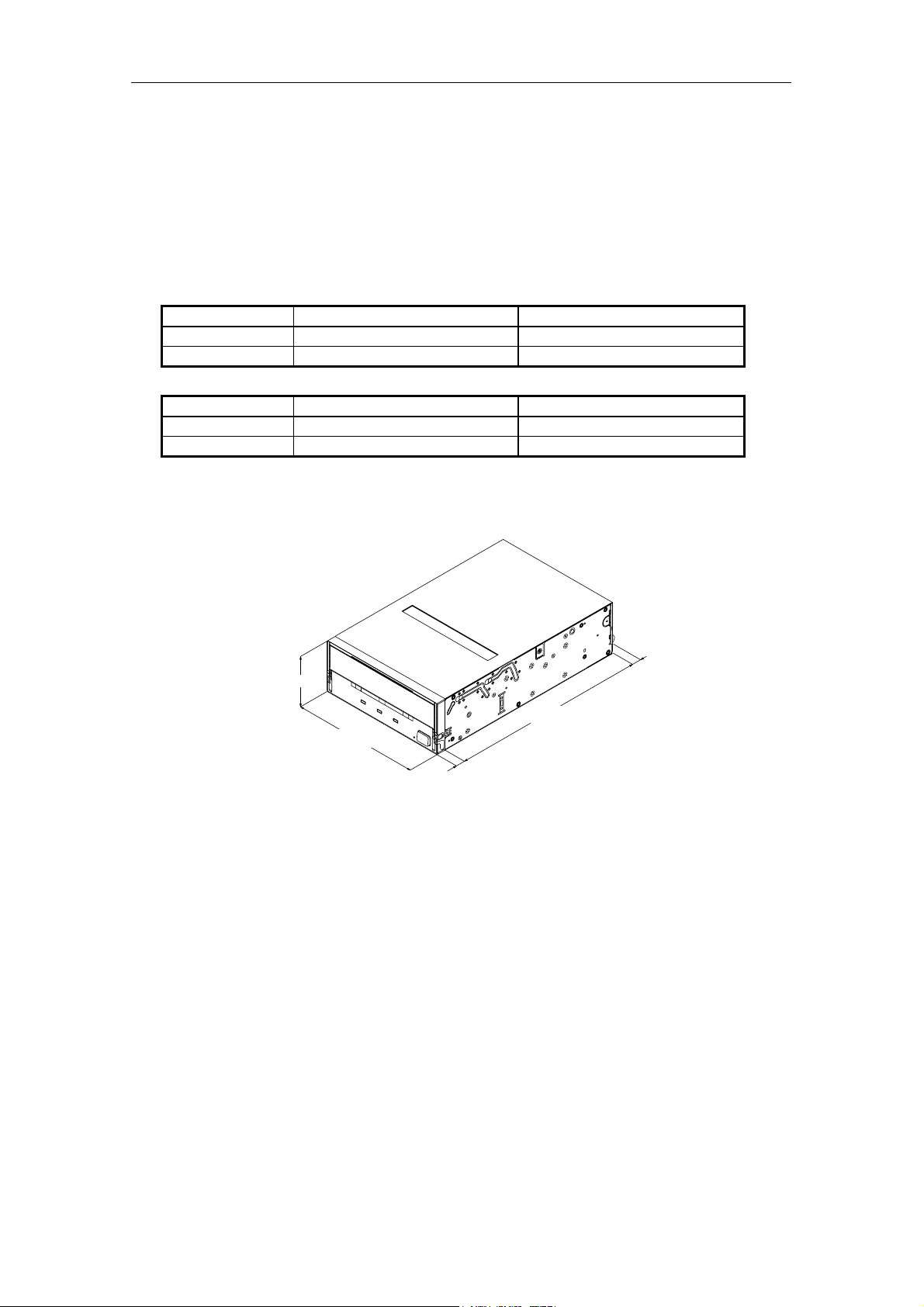
2.1.1. Dimensions
The SDX-560V/P
Height 41.2 mm (1.62 in) ± 0.5 mm (0.02 in)
Width 101.6 mm (4.00 in) ± 0.5 mm (0.02 in)
Depth 155.0 mm (6.10 in) ± 0.5 mm (0.02 in)
The SDX-560V/RP
Height 41.2 mm (1.62 in) ± 0.5 mm (0.02 in)
Width 146.0 mm (5.75 in) ± 0.5 mm (0.02 in)
Depth 155.0 mm (6.10 in) ± 0.5 mm (0.02 in)
Note: The above dimensions do not include the front panel thickness, eject button and IDE connector.
Height 41.2 0.5mm
[1.62" 0.02"]
_
+
_
+
Width 101.6 0.5mm
_
+
[4.00" 0.02"]
_
+
_
+
7.4 0.6mm
_
+
[0.29" 0.02"]
Figure 2-1: Dimensions (SDX-560V)
_
Depth 155.0 0.5mm
[6.10" 0.02"]
+
_
+
_
+
7.6
0.5mm
_
+
[0.30" 0.02"]
SONY AIT-2 Turbo drive SDX-560V series Ver.1.0
2-1
2. Specification
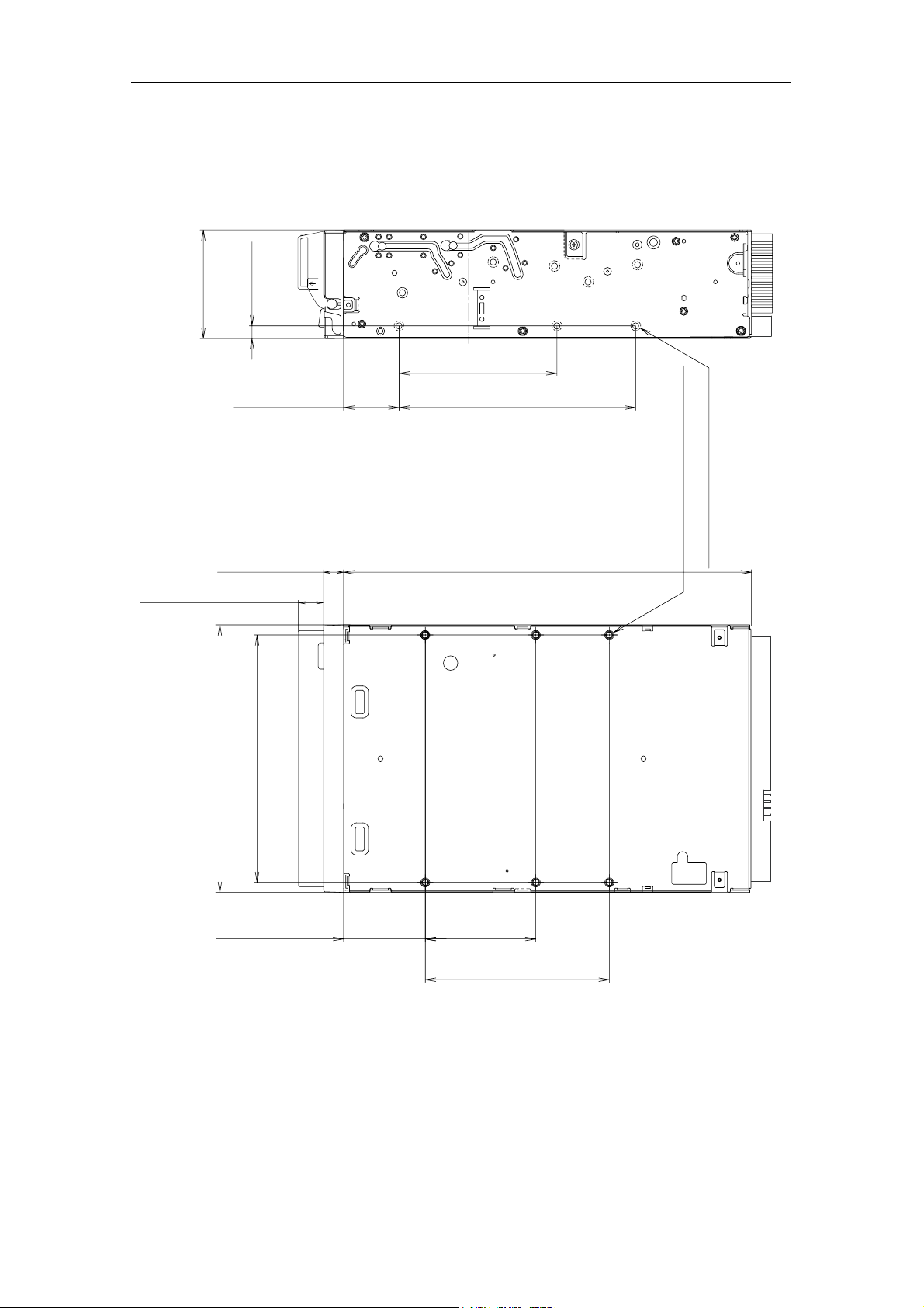
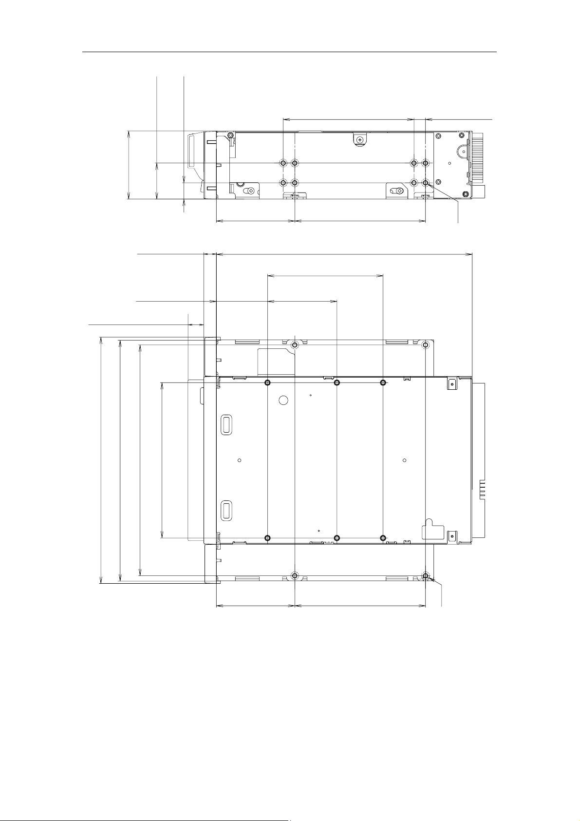
2.1.1.1. Mounting Holes
Figure 2-2a gives details of the mounting holes for the Sony SDX-560V/P and figure 2-2b for the Sony
SDX-560V/RP.
4.8 0.5mm
[0.19" 0.02"]
41.2 0.5mm
[1.62" 0.02"]
+
+
_
+
_
_
+
_
_
+
21.0 0.3mm
_
+
[0.83" 0.01"]
_
+
60.0 0.3mm
_
+
[2.36" 0.01"]
_
+
90.0 0.3mm [3.54" 0.01"]
_
+
6-M3 (depth 2.5mm [0.10"] max.)
6-M3 (depth 2.5mm [0.10"] max.)
_
+
7.4 0.6mm
_
+
[0.29" 0.02"]
_
+
9.8 0.6mm [0.39" 0.02"]
_
+
101.6 0.5mm [4.00" 0.02"]
94.0 0.5mm [3.70" 0.02"]
+
_
+
_
+
_
+
_
_
+
31.0 0.3mm
_
+
[1.22" 0.01"]
_
+
155.0 0.5mm [6.10" 0.02"]
_
+
42.0 0.3mm
_
+
[1.65" 0.01"]
_
+
70.0 0.3mm [2.76" 0.01"]
_
+
_
+
2-2
Figure 2-2a: SDX-560V/P Mounting Holes
SONY AIT-2 Turbo drive SDX-560V series Ver.1.0
2. Specification
21.8 0.5mm
[0.86" 0.02"]
+
_
41.2 0.5mm
[1.62" 0.02"]
+
_
+
_
9.9 0.5mm
[0.39" 0.02"]
+
+
_
+
_
_
_
+
_
+
79.2 0.3mm [3.12" 0.01"]
_
+
7.0 0.5mm
_
+
[0.28" 0.02"]
7.6mm [0.3"]
_
+
7.4 0.6mm
_
+
[0.29" 0.02"]
_
+
31.0 0.3mm
_
+
[1.22" 0.01"]
_
+
9.8 0.6mm
_
+
[0.39" 0.02"]
139.6 0.5mm [5.50" 0.02"]
146.0 0.5mm [5.75" 0.02"]
149.0 0.5mm [5.87" 0.02"]
+
_
+
_
+
_
+
_
94.0 0.5mm [3.70" 0.02"]
+
_
+
_
+
_
+
_
_
+
47.5 0.3mm
_
[1.87" 0.01"]
+
_
+
79.2 0.3mm [3.12" 0.01"]
_
+
155.0 0.5mm [6.10" 0.02"]
_
+
70.0 0.3mm [2.76" 0.01"]
_
42.0 0.3mm
+
_
[1.65" 0.01"]
+
_
+
6-M3
_
+
_
+
_
+
47.5 0.3mm
_
+
[1.87" 0.01"]
Figure 2-2b: SDX-560V/RP Mounting Holes
SONY AIT-2 Turbo drive SDX-560V series Ver.1.0
_
+
79.2 0.3mm [3.12" 0.01"]
_
+
4-M3
2-3
2. Specification
2.1.2. Weight
SDX-560V/P 780 grams, without a cassette and a front bezel.
SDX-560V/RP 1050 grams, without a cassette and a front bezel.
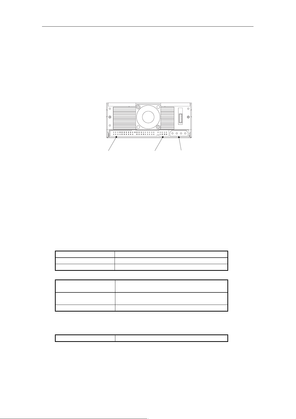
2.1.3. Connectors
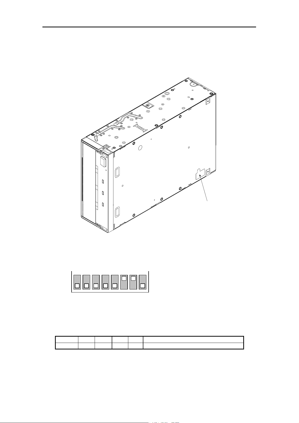
The SDX-560V has a IDE connector with a power connector and Jumpers at the positions shown in Figure 2-3. All
other connectors are for use by Sony’s manufacturing and service facilities only.
IDE Connector
Figure 2-3: Connector Positions
Jumpers
Power Connector
2.1.3.1. IDE Cables
ATA/ATAPI-6 configuration are supported by SDX-560V.
The hardware specification of this interface can be found in Annex A connectors and cable assemblies of the ANSI
INCITS 361-2002.
2.2. Environmental Specifications
The specifications which apply when media is present may be different than these.
2.2.1. Temperature and Humidity Range
Temperature
Operating 5 °C to 40 °C (∆T < 10 °C/h)
Non-Operating (mech.) -40 °C to 70 °C (∆T < 20 °C/h)
Non-Operating (tape) -40 °C to 45 °C (∆T < 20 °C/h)
Humidity
Operating 20 to 80% RH, non-condensing
Maximum wet bulb temperature: 26 °C
Non-operating (mech.) 5 to 95%RH (∆RH<30%/h)
Maximum wet bulb temperature: 45 °C
Non-operating (tape) 20 to 80%RH (∆RH<30%/h)
Note: Please keep cool the drive's heatsink.
2.2.2. Altitude
Operating 0 to 10,000 feet
2-4
SONY AIT-2 Turbo drive SDX-560V series Ver.1.0

2.2.3. Suspended Particulate
2. Specification
Operating
Less than 150 microgram/m
Based Sampling period 24 hours
3
2.2.4. Vibration
Operating Swept Sine 5 to 500Hz, @0.25G Peak 1 Octave/min.
3 axis, 3 directions
Non-operating Swept Sine 5 to 500Hz, @ 0.5G Peak 1 Octave/min.
3 axis, 3 directions
2.2.5. Shock
Operating No Data Loss
Half Sine
Performance
5 G Peak 3 ms
3 axes, 3 directions
*Interval 10 seconds
Non-operating No Device Damage
Half Sine
90 G Peak 3 ms
(30 G Peak 11 ms)
3 axes, 3 directions
*
Interval 10 seconds
2.2.6. Acoustic Noise
The ambient noise level is no greater than 25 dB (A). The sound-meter on (A) scale is located 1m in front of the
center of the drive front panel. (A): A curve weight
Streaming Write/Read 35dB (A)
Insert/Eject 60dB (A)
2.2.7. ESD
Front Panel Only, Integrated
product
Discharge Voltage
Less than 15kV: No operation failure
Less than 20kV: No drive damage
2.2.8. EMI
Radiated Emissions/
Conducted noise Emissions
EN55022 (1998) class B
EN55024 (1998) A1 (2001)+A2 (2003) class B
SONY AIT-2 Turbo drive SDX-560V series Ver.1.0
2-5
2. Specification
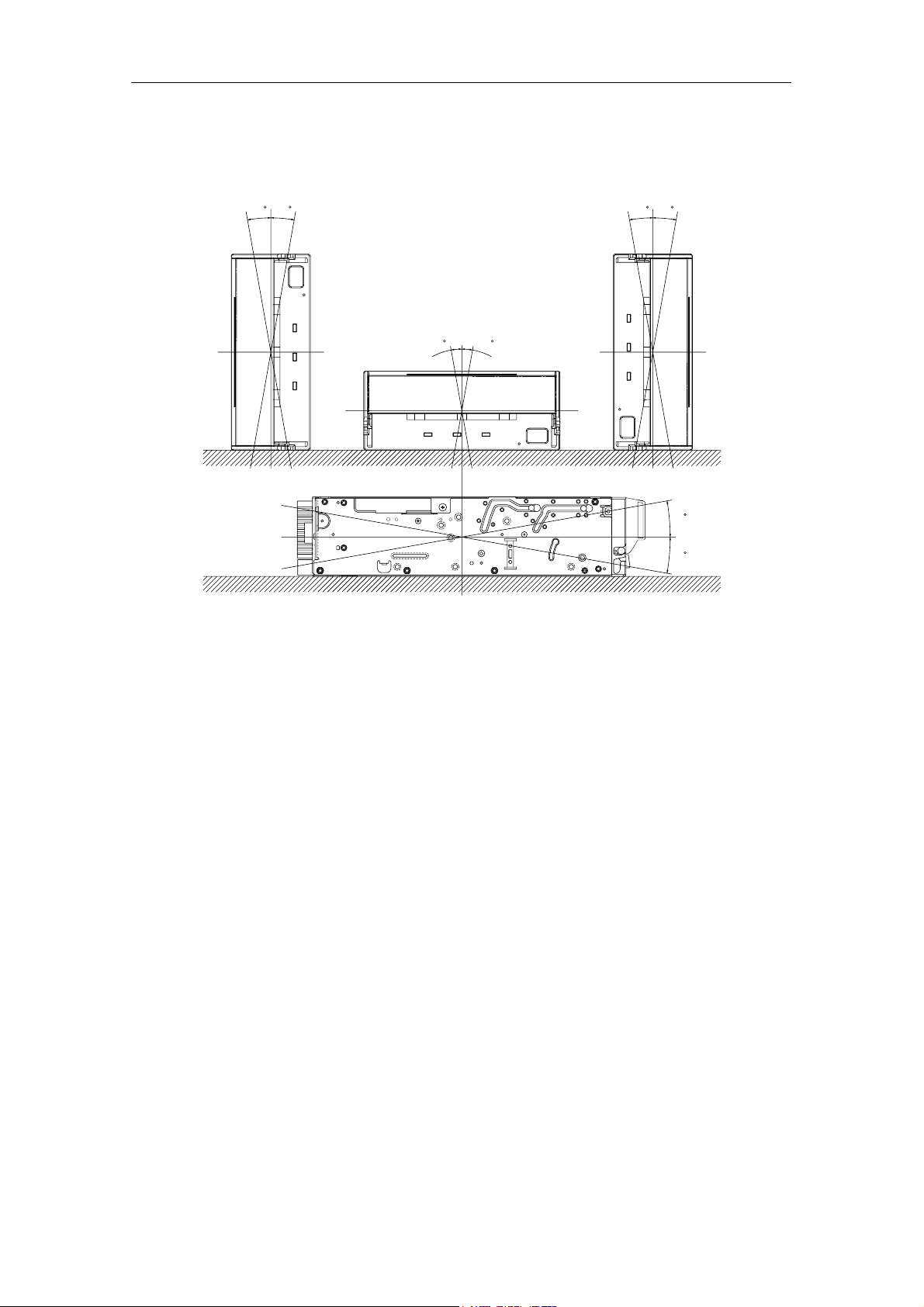
2.2.9. Orientation
The SDX-560V can be installed in three different mounting positions as shown in the figure below. Each position has
a maximum tolerance of ±10 degrees.
10
10
10
10
10
10
10
10
Figure 2-4: Mounting Attitude and Tolerance
2.3. Performance Specification
The data capacity, data transfer rate and data reliability specifications this chapter require the media to conform to
the AIT-E Turbo, AIT-1 Turbo and AIT-1 Media Specification and also require the drive and media to remain within
their respective operating and non-operating environmental specifications. The specifications below also assume
that the C3 ECC frame is generated on writing and used as necessary on reading, and further assumes that
read-after-write rewrites are used as necessary on writing.
2-6
SONY AIT-2 Turbo drive SDX-560V series Ver.1.0
2. Specification
2.3.1. Data Capacity
The SDX-560V includes a data compression capability. When data compression is enabled the drive capacity can
increase from 2 times to 3 times. The efficiency of the data compression depends on the actual data that is being
compressed and cannot be predicted precisely prior to compression.
Format AIT-E Turbo Standard Format
Native
Capacity
Format AIT-1 Standard Format
Native
Capacity
Format AIT-1 Turbo Standard Format
Native
Capacity
Format AIT-2 Standard Format
Native
Capacity
Format AIT-2 Turbo Standard Format
Native
Capacity
20.0 Gbyte typical When using 98 meter tape AIT-E Turbo cassette (TAITE-20N)
25.0 Gbyte typical When using 170 meter tape AIT-1 cassette (SDX1-25C)
35.0 Gbyte typical When using 230 meter tape AIT-1 cassette (SDX1-35C)
40.0 Gbyte typical
50.0 Gbyte typical When using 230 meter tape AIT-2 cassette (SDX2-50C)
36.0 Gbyte typical When using 170 meter tape AIT-2 cassette (SDX2-36C)
80.0 Gbyte typical
When using 186 meter tape AIT-1 Turbo cassette (TAIT1-40N and
TAIT1-40C)
When using 186 meter tape AIT-2 Turbo cassette (TAIT2-80N and
TAIT2-80C)
2.3.2. Data transfer Rate
2.3.2.1. Sustained Data Transfer Rate to and from Tape
The sustained transfer rate to and from the tape is 12 Mbyte per second with AIT-E Turbo, AIT-1 Turbo, AIT-2, AIT-2
Turbo cassette. The sustained transfer rate to and from the tape is 8 Mbyte per second with AIT-1 cassette. For this
sustained rate to be achieved, the drive must be streaming. There may be some dependency on the host and
application softwares for this to be achieved.
2.3.2.2. Burst Transfer Rate to and from the IDE Bus
The SDX-560V will transmit and receive data bursts to and from the IDE bus at a maximum burst rate of 100 Mbyte
per second, using Ultra DMA (mode 5) transfer.
2.3.3. Initialize Time
Initialize Time means the period from the time the drive is powered on to the time when the drive is ready and waiting
for a ATA/ATAPI command such as INQUIRY or TEST UNIT READY. Initialize Time is less than 5 seconds.
The drive will respond with BUSY status until the completion of the Initialize Time. The Initialize Time does not
include the time necessary for drive diagnostics to complete and the drive to become ready for tape insertion.
SONY AIT-2 Turbo drive SDX-560V series Ver.1.0
2-7

2. Specification
2.3.4. Load Time
Load Time means the period from the time when the operator inserts a cassette into the drive to the time when the
drive is ready. The data in the below table represents the average time for SDX-560V. The time it may take for
retrying is not reflected here.
Load Time 80 sec 14 sec 14 sec 80 sec 14 sec 14 sec 25 sec 14 sec
TAITE-20N
(98m)
SDX1-25C
(170m)
SDX1-35C
(230m)
TAIT1-40N
(186m)
TAIT1-40C
(186m)
SDX2-50C
(230m)
TAIT2-80N
(186m)
TAIT2-80C
(186m)
2.3.5. Unload Time
Unload Time means the period from the beginning of the unload sequence caused by Unload Command or Eject
button to the time when a cassette is ejected from the slot. Unload Time does not include Rewind time. The data in
the below table represents the average time for SDX-560V. The time it may take for retrying is not reflected here.
Unload Time 25 sec 20 sec 20 sec 25 sec 20 sec 20 sec 25 sec 20 sec
TAITE-20N
(98m)
SDX1-25C
(170m)
SDX1-35C
(230m)
TAIT1-40N
(186m)
TAIT1-40C
(186m)
SDX2-50C
(230m)
TAIT2-80N
(186m)
TAIT2-80C
(186m)
2.3.6. Search Time
Search Time means the period for the drive to find the position that is required by a command. This time also
depends on the tape length and the position of the head along the tape. The data in the below table represents the
average time for SDX-560V. The time it may take for retrying is not reflected here.
Search Time 60 sec 85 sec 120 sec 105 sec 80 sec 120 sec 105 sec 80 sec
TAITE-20N
(98m)
SDX1-25C
(170m)
SDX1-35C
(230m)
TAIT1-40N
(186m)
TAIT1-40C
(186m)
SDX2-50C
(230m)
TAIT2-80N
(186m)
TAIT2-80C
(186m)
2.3.7. Rewind Time
Rewind Time means the period from the beginning to the end of rewinding sequence. This value depends on the
tape length and the position of the head along the tape. The data in the below table represents the average time for
SDX-560V. The time it may take for retrying is not reflected here.
Rewind Time 55 sec 80 sec 105 sec 90 sec 90 sec 105 sec 90 sec 90 sec
TAITE-20N
(98m)
SDX1-25C
(170m)
SDX1-35C
(230m)
TAIT1-40N
(186m)
TAIT1-40C
(186m)
SDX2-50C
(230m)
TAIT2-80N
(186m)
TAIT2-80C
(186m)
2.3.8. Error Rate
The un-correctable bit error rate is expected to be less than 1 in 10 to the 17th.
2.3.9. Retry Limits on Rewrites
For Read-after-Write error correction, each frame can be rewritten up to a maximum of 63 times giving 64 writes of
the frame.
2.3.10. Definition of Failure
A failure is defined as any permanent manufacture of the drive that prevents the user from retrieving data from tape.
This includes failure to power up, failure to unload or eject a cassette, or failure to write and read data to and from the
tape, providing that both the drive and tape are being used within specification.
Faults are not considered failures when they are related to operator error mishandling and abuse, system-related
faults (cabling problems unsupported systems, operating software and so on) no trouble found, and transportation
damage.
2-8
SONY AIT-2 Turbo drive SDX-560V series Ver.1.0
2. Specification
D
P
2.3.11. Mean Time Between Failures
The Mean Time Between Failures (MTBF) for the SDX-560V is 300,000 power-on hours, assuming a duty cycle of
100%, where:
utyCycle = ×100
Tape Motion Time
owerOn Time
2.3.12. Mean Time to Repair
The Mean Time To Repair (MTTR) of the SDX-560V is 30 minutes. Since at the field level the entire drive is
considered a Field Replaceable Unit (FRU) the time to replace the drive with a new one is less that 30 minutes.
2.3.13. Component Life
The specified life of the SDX-560V is 5 years average.
2.3.14. Durability
The durability of the components in the SDX-560V will exceed the number of operations listed on the following table:
Start/Stop 400,000 times
Reposition 3,000,000 times
Thread/Unthread 100,000 times
Load/Eject 100,000 times
2.4. Safety
The SDX-560V conforms to the following safety Standards:
• UL/cUL (Underwriters Laboratories, Inc.)
UL 60950 3rd Edition/CSA C22.2 No. 60950-00
Safety of Information Technology Equipment.
• TUV
EN 60950-1:2001 Safety of Information Technology Equipment including
Electrical Business Equipment
• CE Mark
2.4.1. Conditions of Acceptability
The SDX-560V is for use only in equipment where the suitability of the combination has been determined by an
appropriate certification organization (for example, Underwriters Laboratories, Inc. or the Canadian Standards
Association in North America, and the British Standards Institution or Verband Deutscher Elektrotechniker in
Europe). Other considerations include the following:
1. An enclosure must be supplied to limit the operator’s access to live parts, to provide system stability, and to
furnish the drive with the necessary grounding integrity.
2. The necessary voltage supplies must be provided. These supplies are Extra Low Voltage SEC for UL and CSA,
or Safety Extra Low Voltage for BSI, VDE, and so on, of +5V and +12V DC.
2.5. Installation Requirements
Note: Do not move the drive while it is operating. It may cause malfunction.
SONY AIT-2 Turbo drive SDX-560V series Ver.1.0
2-9
2. Specification
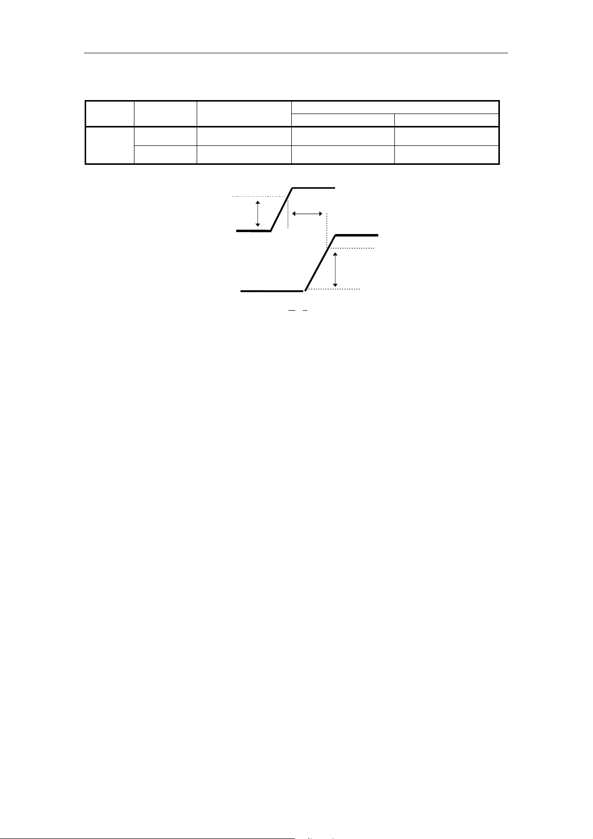
2.5.1. Power Requirements
Voltage Max Ripple
Typical Maximum
Current
5V ± 5% 100 mV p-p 1.4A 1.7A
SDX-560V
12V ± 10% 150 mV p-p 0.5A 1.2A
4.75V
5V
12V
-300 ms <
T
T < 300 ms
10.8V
Figure 2-5: Power-up Sequence
Note: Voltage has to increase constantly during Power-up until Maximum is reached.
Do not turn off the drive while the tape is in the drive.
2.6. Data Compression
The tape capacity is increased by compressing data prior to writing it to the tape. Data compression is a well
established technology for reducing the number of bits used to represent data in order to improve data transfer rate
as well as reduce the amount of storage space consumed by the data. The compression ratio depends on the source
file type. The SDX-560V uses the ALDC Data Compression algorithm. ALDC is ECMA standard data compression
algorithm. (ECMA-222) The Data Compression control page allows the host computer to enable data compression
and decompression and also configure the way in which the drive responds to compressed/uncompressed data
boundaries on the tape. The AIT-E Turbo, AIT-1 Turbo, AIT-1, AIT-2 Turbo and AIT-2 Format allows both
compressed and uncompressed data to reside on the same tape.
The Sony SDX-560V has a DIP switch to disable the Data Compression/ Decompression. After power-on reset with
this DIP switch set, both data compression and data decompression are disabled However, a MODE SELECT
command can override the setting of this DIP switch. After power-on reset without this DIP switch set, both data
compression and data decompression are enabled. (See clause 3.1.5)
2-10
SONY AIT-2 Turbo drive SDX-560V series Ver.1.0
3. Installation
3.1. Installation Guide
This Product Specification Manual is applicable for SDX-560V drive.
3. Installation
Figure 3-1: DIP switch
1 Drive Mode-1
ON
OFF
1 2 3 4 5 6 7 8
Figure 3-2: DIP Switch positions
Table 3-1: Drive Mode
DIP SW 1 2 3 4 MODE
OFF OFF OFF OFF Normal
2 Drive Mode-2
3 Drive Mode-3
4 Drive Mode-4
5 Reserved (OFF)
6 Periodic Cleaning Req (ON)
7 DC Control-1 (ON)
8 DC Control-2 (OFF)
Dip switch
SONY AIT-2 Turbo drive SDX-560V series Ver.1.0
3-1
3. Installation
Table 3-2: Periodic Cleaning Request (Refer to 4.5.1.2)
DIP SW 6 Definition
OFF Disable Periodic Cleaning Request
ON Enable Periodic Cleaning Request
3.1.1. Data Compression ON Switch
Data compression can be selected by DIP switch.
DC Control-1 DC Control-2 Definition
OFF OFF Compression disabled at power-on. The host is allowed to control
compression.
OFF ON Compression disabled at power-on. The host is not allowed to control
compression.
ON OFF Compression enabled at power-on. The host is allowed to control
compression.
ON ON Compression enabled at power-on. The host is not allowed to control
compression.
Figure 3-3: Data Compression Switches
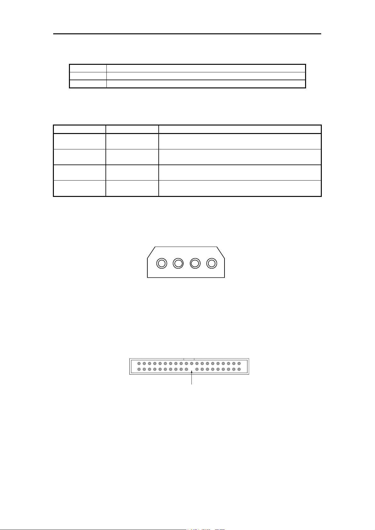
3.1.2. Power Connector
The power connector is illustrated as Figure 3-4.
4 3 2 1
5V GND GND 12V
Figure 3-4: Power Connector
3.1.3. IDE Interface Connector
Figure 3-5 illustrates IDE 40 pin connector and table 3-3 shows the assignments for the pins of the connector.
Pos 39 Pos 1
Pos 40
Pos 20 (Pin removed)
Figure 3-5: IDE Device Connector
Pos 2
3-2
SONY AIT-2 Turbo drive SDX-560V series Ver.1.0
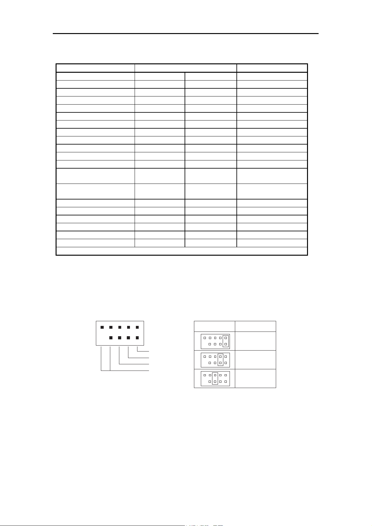
Table 3-3: 40 pin connector interface signals
Signal Name Cable Conductor Number Signal Name
RESET- 1 2 Ground
DD7 3 4 DD8
DD6 5 6 DD9
DD5 7 8 DD10
DD4 9 10 DD11
DD3 11 12 DD12
DD2 13 14 DD13
DD1 15 16 DD14
DD0 17 18 DD15
Ground 19 20 (keypin)
DMARQ 21 22 Ground
DIOW-:STOP 23 24 Ground
DIOW-:HDMARDY-
:HSTROBE
IORDY:DDMARDY-
:DSTROBE
DMACK- 29 30 Ground
INTRQ 31 32 Obsolete (see note)
DA1 33 34 PDIAG-:CBLIDDA0 35 36 DA2
CS0- 37 38 CS1-
DASP- 39 40 Ground
NOTE-Pin 32 was defined as IOCS in ATA-E Turbo, AIT-1 Turbo, ANSI X3.279-1996.
A dash character (-) at the end of a signal name indicates the signal is low active signal.
25 26 Ground
27 28 CSEL
3. Installation
3.1.4. Jumper Connector
The DEVICE number of SDX-560V is selected by jumpers.
Below figure shows the jumper configuration.
Master
Slave
CSEL
No connection
Jumper Drive Setting
Master
Slave
Cable Select
SONY AIT-2 Turbo drive SDX-560V series Ver.1.0
3-3
3. Installation
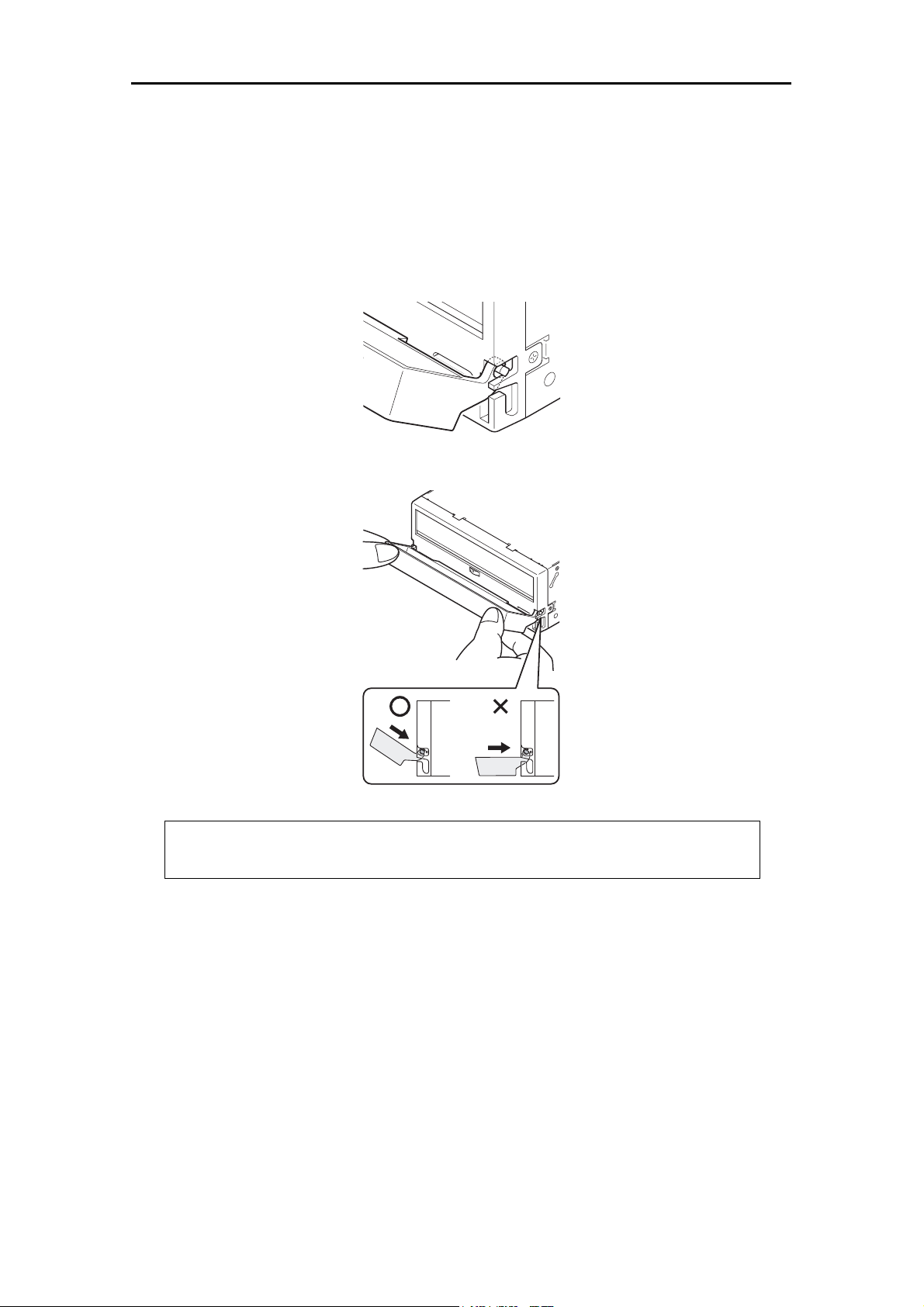
3.1.5. Attaching and Removing the Dust Cover
3.1.5.1. Attaching the Dust Cover
(1) Align the dust cover’s hinge clips (one on each side) with the pins of the drive bezel.
• The dust cover should be positioned so that the six magnets on the cover’s back face the drive bezel.
• Holding the dust cover at an angle as shown in the figure below, set the hinge clips on top of the bezel pins,
positioning them so that they bracket the pins.
(2) Press down at an angle on each side in turn until you hear the hinge clips click into place.
Caution:
Do not press the dust cover in horizontally from the side. Doing so could cause the dust cover to break.
(3) Close the dust cover.
This completes attachment of the dust cover.
3-4
SONY AIT-2 Turbo drive SDX-560V series Ver.1.0

3.1.5.2. Removing the Dust Cover
(1) Open the dust cover.
(2) Holding the dust cover at both corners, carefully raise the dust cover.
The dust cover hinge clips and drive bezel pins uncouple.
3. Installation
SONY AIT-2 Turbo drive SDX-560V series Ver.1.0
3-5

3. Installation
This page intentionally left blank.
3-6
SONY AIT-2 Turbo drive SDX-560V series Ver.1.0
4. Operation
4. Operation
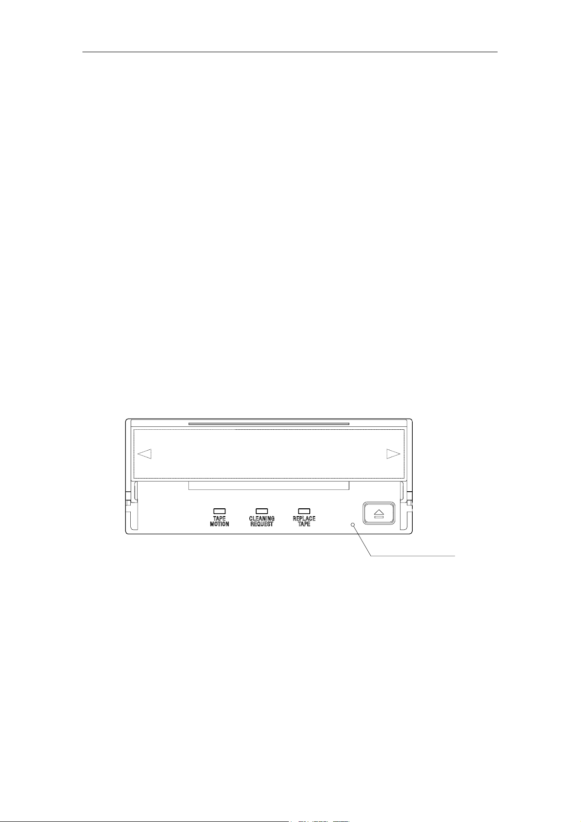
4.1. Summary of LED Indications
The SDX-560V have 3 LEDs. Each LED shows "Tape Motion", "Cleaning Request", and "Replace Tape" as defined.
"Tape Motion" to show the tape motion in the drive.
"Cleaning Request" to be on, when CLEANING is required.
"Replace Tape" to be on, when the tape needs to be replaced. It should be on when a medium error occurred.
All of three LEDs flash fast simultaneously, when the drive is in malfunction.
The following table shows the meaning of each LED indications:
Table 4-1: Meaning of each LED indications
LED Tape Motion Cleaning Request Replace Tape
Off No Tape Cleaning is Not Necessary No Media Error Occurred
On Tape Loaded Cleaning Request Media Error Occurred
Flash Slowly Tape Access in Progress
(Write/Read)
Flash Fast Tape Access in Progress
(Others)
All LED Flash Fast H/w Error Occurred
Cleaning is Not Completed
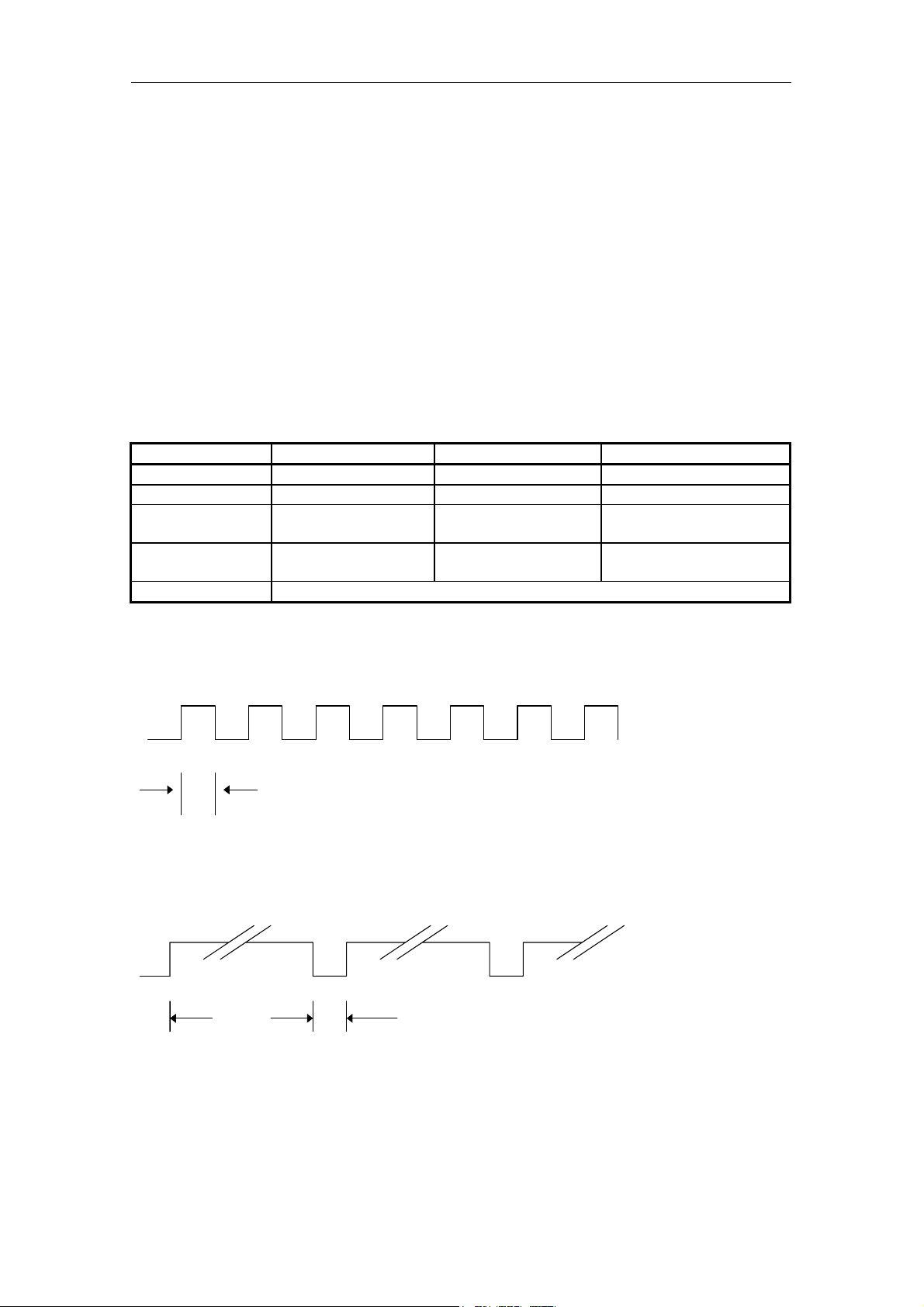
Flash Fast (0.3sec on/0.3sec off)
0.3 sec
Flash Slowly (0.9sec on/0.3sec off)
0.9sec 0.3sec
SONY AIT-2 Turbo drive SDX-560V series Ver.1.0
4-1
4. Operation
4.2. Operator Action
4.2.1. Powering Up the SDX-560V
After the initial installation of the SDX-560V has been verified, power can be applied to the unit. The +12V and +5V
power must be applied simultaneously. (See Figure 2-5) The SDX-560V will execute a power-up diagnostic and then
comes ready.
Once the tape has been loaded the SDX-560V sends a CHECK CONDITION response on receipt of the next
ATA/ATAPI command from the host. The UNIT ATTENTION key is set in the returned REQUEST SENSE data to
indicate that the tape may have been changed. (Sense Key/ASC/ASCQ=06/28/00)
4.2.2. Inserting Cassettes
The operator inserts a cassette into the slot on the front panel. As the cassette is inserted, the drive takes it and
automatically loads it into the drive mechanism. The SDX-560V performs a tape load sequence as described in
clause 4.3.1
4.2.3. Removing Cassettes
The cassette can be removed from the SDX-560V either in response to a ATA/ATAPI UNLOAD command, or by
pressing the Eject button. The operator uses the Eject button to initiate the unload sequence (see clause 4.3.2). The
mechanism winds the tape to Beginning of Media (BOM), unthreads it, and ejects the cassette from the slot.
Operation of the Eject button is disabled if the host has previously sent an ATA/ATAPI PREVENT ALLOW MEDIA
REMOVAL command with prevent bit set to one. In this case, pressing the Eject button has no effect, and does not
initiate an Unload sequence. The Eject button returns to normal operation following receipt of an PREVENT ALLOW
MEDIA REMOVAL command with prevent bit clear.
4.2.4. Hard Reset Hole
Hard reset hole
In case of emergency, you can immediately reset the drive itself by pushing the switch in the “Hard Reset Hole” with
the tip of a pin. However, there is a risk of losing data upon execution of this operation in the Write or Read mode.
The hardware reset operation is only for manufacturing and repair purposes.
4-2
SONY AIT-2 Turbo drive SDX-560V series Ver.1.0
4. Operation
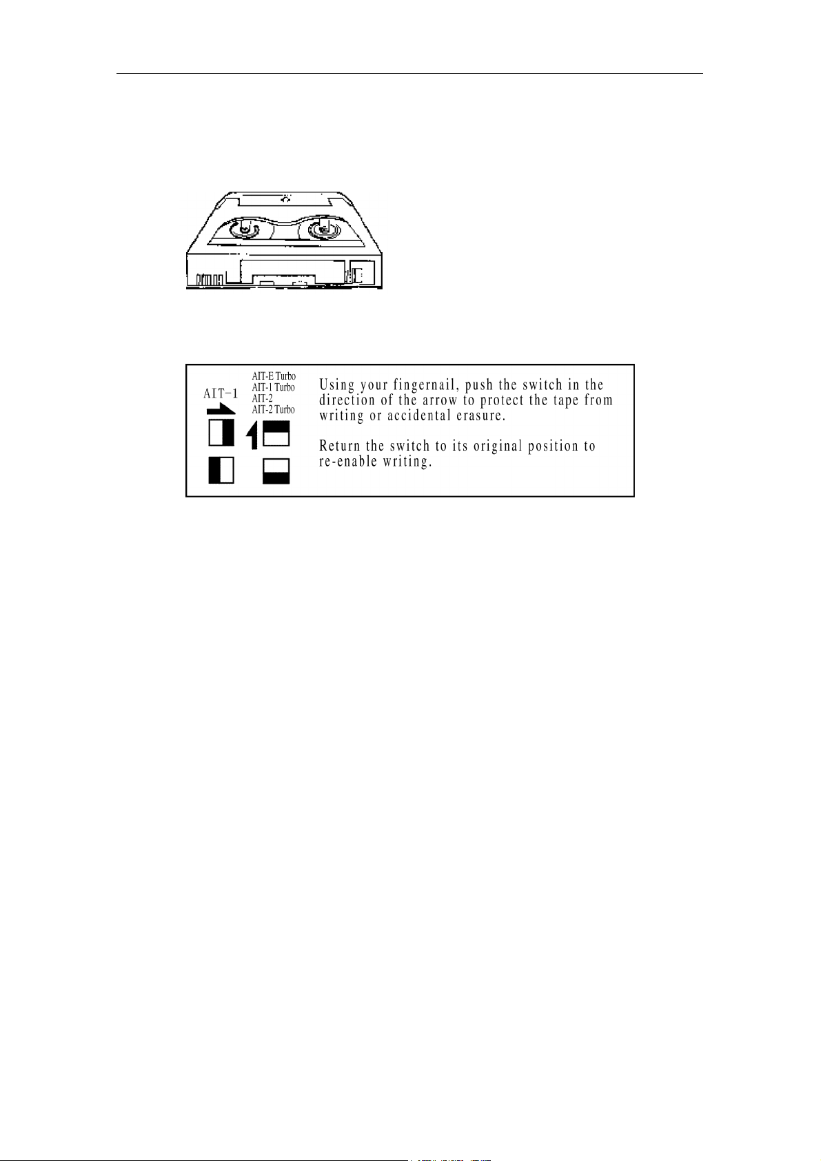
4.2.5. Write-Protecting Cassettes
Cassettes can be write-protected by sliding the tab on the back of the cassette open. In this state, data can be read
from the tape but not written to it.
Caution: The Tape Log, which contains a history of usage of the tape, will not be updated when the cassette is
write-protected. It follows that the Tape Log becomes inaccurate if a cassette is used write-protected, and the media
warning cannot be relied on to indicate that the cassette needs to be copied and replaced.
4.3. Internal Function
4.3.1. The Load Sequence
Refer to 14.2.1 Fast Media Load/Unload (Effective for SDX1-25C, SDX1-35C, TAIT1-40C and TAIT2-80C MIC
cassette)
During load sequence, the following occurs:
(1) The drive mechanism accepts the cassette and threads the tape. The tape is then moved to Beginning-of-Tape
(2) The System area is then accessed and the System log is read into the drive.
(3) Finally the drive goes on-line.
In the case of 2 partition tape the drive detects that the tape has been formatted as a two partition tape when the
Reference Area is read. The drive will then automatically position to the beginning of partition 0 before coming on
-line. Partition 0 is the partition that begins the furthest from BOM.
(BOT) and the Reference area is checked to find the tape format. If the format is not AIT-1, the drive rewinds
the tape to BOT and awaits either a Write, Partitioning, Mode Select or an UNLOAD command.
(Effective for SDX-T3N, TAITE-20N, TAIT1-40N and TAIT2-80N)
4.3.2. The Unload Sequence (Effective for SDX-T3N, TAITE-20N, TAIT1-40N and TAIT2-80N)
Refer to 14.2.1 Fast Media Load/Unload (Effective for SDX1-25C, SDX1-35C, TAIT1-40C and TAIT2-80C MIC
cassette)
The drive will always write any buffered data out to tape followed by an EOD prior to initiating the Unload sequence.
During this sequence the tape is rewound to BOT and, if the tape is write-enabled, the copy of the tape log held in
RAM is written back to tape. The tape is then rewound to BOM and the tape unthreaded from the mechanism. At this
stage the tape is either retained in the drive or ejected, depending on media removal is enabled by the Prevent Allow
Media Removal command.
In the case of two partition tape the drive detects that the tape has been formatted as a two partition tape when the
Reference Area is read during the load sequence. When the Unload operation begins the drive will then
automatically update the Tape Log for each partition before unloading the tape.
SONY AIT-2 Turbo drive SDX-560V series Ver.1.0
4-3
4. Operation
4.3.3. Power-Fail Handling
If there is a power-fail, the SDX-560V performs the following actions, and reverts to its default configuration:
(1) The drive remains positioned at the point where the power-fail.
(2) It executes the Power-Up sequence of self-tests. (When power is restored.)
(3) If a tape is in the drive, the SDX-560V starts a LOAD sequence. The drive rewinds the tape to BOT and remains
on-line.
(4) The drive returns CHECK CONDITION status for the first command after the power-fail or Reset. The next
command from the initiator should be a REQUEST SENSE. The drive will return sense data including a sense
key that will indicate that the drive has been reset. (Sense Key/ASC/ASCQ=06/29/00)
4.3.4. Diagnostic and Normal Status Displays
This chapter describes LED displays while the SDX-560V is starting up. When power is turned on, the SDX-560V will
go through its diagnostics to reach normal status. When a failure is detected during diagnostics, the LEDs show that
the SDX-560V is out of order and needs to be repaired.
Note: When power is turned on, the all LED on before the front panel test.
4.3.4.1. Diagnostic Status Display
The SDX-560V starts with its Diagnostic function. This is made up of the Front Panel Test and the Kernel Test.
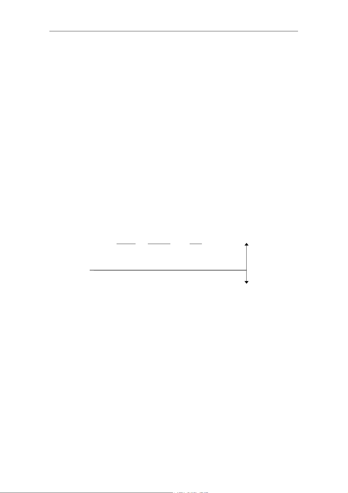
Front Panel Test
LED display sequence:
This function is for checking TAPE MOTION, CLEANING REQUEST, REPLACE TAPE LEDs and the related
circuits. No errors can be generated as this test is only for operator verification of indicator operation.
Kernel Test
After the Front Panel Test, the SDX-560V checks its internal units. When a Diagnostic error occurs, all LED flash
fast. Then the SDX-560V must be powered off. The SDX-560V will not work and should be checked or repaired
immediately.
0.3sec on on on
0.3sec - - -
0.3sec on on on
0.3sec - - - Front Panel Test
0.3sec on - - Kernel Test
0.3sec - on -
0.3sec - - on
0.3sec on - -
0.3sec - on -
0.3sec - - on
0.3sec on - -
TAPE CLEANING REPLACE
MOTION
REQUEST TAPE
The purpose of the diagnostic firmware to test the SDX-560V electronics for functionality. If the diagnostic request
comes from the host through IDE, then the results are reported through IDE.
If the electronics are not functioning, the diagnostic firmware tries to isolate the non-functional area to a specific
Failed Unit. Given a failure, the firmware decides on an hierarchical basis which Unit to designate as the Most
Suspect Failed Unit (MSFU). The confidence in this decision is intended to be 95%. For the details of Diagnostics,
see clause 7.2.6
4-4
SONY AIT-2 Turbo drive SDX-560V series Ver.1.0

4. Operation
4.3.4.2. Normal Status Display
After the Diagnostic Display, when no failures are detected, the SDX-560V is in the Normal Status. The LEDs show
various Normal Status (No Error) indications as shown in the table below:
Table 4-2: Normal LED indications
LED Tape Motion Cleaning Request Replace Tape
Off No Tape Cleaning is Not Necessary No Media Error Occurred
On Tape Loaded Cleaning Request Media Error Occurred
Flash Slowly Tape Access in Progress
(Write/Read)
Flash Fast Tape Access in Progress
(Others)
All LED Flash Fast H/w Error Occurred
Cleaning is Not Completed
4.4. Tape Format
The SDX-560V is an implementation of the Advanced Intelligent Tape (AIT-E Turbo, AIT-1, AIT-1 Turbo, AIT-2 and
AIT-2 Turbo) format, a standard developed by Sony for 8mm data storage drives.
- C1,C2, first and second level Error Correction Code, providing correction for random and Burst Symbol errors.
- C3 ECC, third level Error Correction Code, providing correction across frames within groups
- Read-After-Write, where data is verified immediately after it is written and re-written if there is any error.
- Randomizer, to reduce inter-symbol interference.
4.4.1. Tape Partitions
Tapes can be formatted as a single data space or as two partitions. With two partitions, each has the same structure
and can be written independently. Some for example, the partition further from BOM (Partition 0) can contain data
files, and the partition closer to BOM (Partition 1) could contain a directory of these files, written later.
With the exception of the Device area on the tape, each partition of a 2-partition tape is identical to a single data
space tape in structure. This means each partition has its own Tape Log area; this is necessary because the patterns
of usage may be very different for each partition. Similarly, each has its own Vendor Group, because the partitions
might be written by different drives.
4.4.1.1. Formatting Partitions
The ATA/ATAPI MODE SELECT command is used to create partitions on a tape. The command can perform the
following operations:
- Set up two partitions on a blank tape.
- Convert a single data space tape to a 2-partition tape.
- Convert a 2-partition tape to a single data space tape.
- Change the size of both partitions on a 2-partition tape.
- Re-size the partitions of a 2-partition.
Note: Formatting is not needed for single partition operation.
The MODE SELECT, Medium Partitions Parameters Page (11h) is used to Format the tape. MODE SELECT,
Device Configuration Page (10h) is used to change from one partition to another, see the MODE SELECT Command
description in the ATA/ATAPI command clause of this manual. The LOCATE Command also has the capability to
select a partition prior to positioning.
Any data on the tape before the format pass becomes inaccessible, even if the format pass is intended only to
change the size of the two partitions. The Tape Logs are also destroyed and new logs created.
If you do not format a new tape, it will be organized as a single data space tape. After data has been written to it,
whether it was first initialized or not, a format pass is necessary to alter its characteristics and hence how it is handled
by the tape drive system.
SONY AIT-2 Turbo drive SDX-560V series Ver.1.0
4-5

4. Operation
Note: The format operation can be very time consuming depending on the requested size of the first partition on the
tape. The amount of time required can be approximated by use of the following formula:
- Number of Megabytes in Partition 1 × 0.006 = number of minutes required
- Add 30 additional seconds for processing overhead
4.5. Maintenance, Troubleshooting and Service
4.5.1. Head Cleaning
In case of SDX-560V,a cleaning function which prevents and recovers from head contamination is built in the drive.
However, to keep optimum Read/Write performance, cleaning cassette is recommended to use.
4.5.1.1. Message When Cleaning Cassette is Necessary
When drive displays cleaning cassette requirement, (Cleaning Request LED is on or in case of ATA/ATAPI, CLN bit
is set at Request Sense.) use specified cleaning cassette (model name: SDX1-CL )
4.5.1.2. The Condition of Cleaning Request
(1) Read/Write performance decreased.
(2) Every 100 hours of operation
Note: (2) is enable when Periodic Cleaning Req Dip-SW6 is on.
4.5.1.3. Usage of Cleaning Cassette
(1) Drive displays cleaning cassette requirement.
(2) When specified cleaning cassette is inserted, automatic cleaning operation starts and when its over, the
cassette is ejected.
(3) One cleaning cassette can be used approximately 60 times.
(4) When the Cleaning Request LED indicates "Cleaning is Not Completed", it is possible that there were no more
cleaning tape left. Since cleaning tape cannot be used twice, please insert new cleaning cassette in this case.
(5) SDX1-CL can be inserted in other drives or consumer 8 mm drives, but you cannot expect good effect.
(6) The drive will automatically eject cleaning cassette for consumer drives or for any other format. The cleaning
Request is indicated by the Starts LED flashing:
- on for 3.5 seconds
- off for 0.5 seconds
4.5.2. Troubleshooting Guide
Problems encountered while operating the Sony SDX-560V tape drive fall into two categories: Operational problems
and Read/Write problems.
Operational problems include any conditions that prevent the tape drive from operating. Operational problems
usually are discovered the first time the drive is installed on a system or when the system configuration is changed or
physically moved.
Read/Write problems include conditions that effect the transfer of data to and from the tape drive. Commands such
as REWIND, REQUEST SENSE and UNLOAD perform normally but data transfers fail.
The following clauses describe the recommended procedures for solving operational and read/write problems.
4-6
SONY AIT-2 Turbo drive SDX-560V series Ver.1.0

4. Operation
r
4.5.2.1. Operational Problems
The tape drive will not accept a tape cartridge
Withdraw the tape cassette and turn the power to drive off, wait 5 seconds, then back on. Observe the drive for a
normal power up sequence (see clause 4.3.4). If the LEDs do not light, check the power supply and power cable
connection. If the drive completes the power on sequence normally but still won’t accept the tape cassette, the drive
may be defective.
A tape may already be in the drive. TAPE MOTION LED is on. Press EJECT to remove the first tape. The power has
been removed from the drive with a tape loaded. When the power is restored to the drive, it will detect the tape and
rewind the tape to BOT. Press EJECT remove the cassette.
A tape is in the drive and will not eject.
If the ATA/ATAPI command PREVENT ALLOW MEDIA REMOVAL (with Prevent bit set to one) has been sent to the
drive, the cartridge will be retained in the drive even after an UNLOAD command. The EJECT button is also disabled.
Send an PREVENT ALLOW MEDIA REMOVAL (with prevent bit clear) command, or power the drive off and back on
to override this condition.
If Tape is still in the drive after following the above procedure. The drive has a serious problem and should be
returned to Sony for repair with the tape in place.
Note: If it is absolutely mandatory that the tape cassette be removed prior to returning the drive for repair the
following Emergency Cassette Removal procedure should be followed:
Caution: This procedure should only be attempted by a mechanically qualified person and will probably result in the
tape being unusable. Do not proceed if further damage to the tape drive would be done.
Reel motor
Photo 4-1: Emergency Tape Removal Procedure
Loading moto
Emergency Cassette Removal Procedure
1. Remove the drive from the chassis or enclosure to allow access to the bottom of the drive.
2. Remove the drive’s top cover.
3. Locate the small opening in the bottom of the drive and insert the tip of a precision screwdriver so that the
Loading motor shaft can be rotated.
4. Rotate the motor shaft clockwise to bring the threading mechanism back to the initial position.
SONY AIT-2 Turbo drive SDX-560V series Ver.1.0
4-7

4. Operation
pe g
A
Tape guide surface
Ta
uide surface
C
B
Detail A
Cartridge
Photo 4-2: The Initial Position of the Threading Mechanism
Caution:
Stop rotating the motor shaft immediately, when the guide B (see detail A of Photo 2) gets to the area
below the line C-C (This line is defined by 2 circular tape guide surfaces of the cartridge). Otherwise the
gear of the drive can be damaged.
5. Before manual eject procedure, tape slack must be removed in order to prevent tape damage. Rotate the gear
mechanism located on the bottom of the drive counterclockwise to tighten the tape.
6. After the tape slack has been removed, continue to turn the Loading moter shaft located on the bottom of the
drive clockwise by a precision screwdriver until the tape cartridge is lifted out of the drive mechanism and is
ejected.
7. Return the drive to Sony for repair.
C
The drive powers up properly and loads and unloads tapes but will not respond to any ATA/ATAPI
commands.
If host does not recognize the tape drive:
- Check the IDE cable connectors
- Check Jumper setting
- Check IDE cable pin one is aligned with the IDE connector pin one
- Check for a broken cable or defective connector
- Try another known good IDE device in the same location
4-8
SONY AIT-2 Turbo drive SDX-560V series Ver.1.0

4. Operation
4.5.2.2. Read/Write Problems
To prevent read/write errors, follow the cleaning recommendation in clause 4.5.1 If a read/write error occurs, a
combination of the following steps should correct the problem.
- Remove the tape.
- Clean the drive with the AIT cleaning cartridge.
- Load a new tape in the drive.
- Retry the operation.
Note: If these steps do not correct the problem the drive may be defective and should be returned to Sony for
service.
4.5.2.3. Replace Tape
When Media Error occur drive will indicate that tape is bad by turning on the Replace Tape LED. If this condition
occurs, a combination of the following steps should correct the problem.
- Remove the tape.
- Clean the drive with the AIT cleaning cartridge.
- Load a new tape in the drive.
- Retry the operation.
Note: If these steps do not correct the problem the drive may be defective and should be returned to Sony for
service.
4.5.2.4. Media Warning
When a Media Warning threshold is exceeded the drive will indicate that the tape is bad by flashing the Replace
Tape LED MEW(Media Warning) bit is 1. The indicator will be on for 0.9 seconds, off for 0.3 seconds. The Tape
Motion and Cleaning Request LEDs will operate normally. If this occurs, the data on the cassette should be copied
onto a new one and the old cassette discarded. This status is cleared by unloading the cassette. The Media Warning
is displayed if any of the following conditions are met:
- More than 1,024 RAW retry per 1,024 groups written
- More than 11 read retry or 11 C3 ECC, third level Error Correction Code, per 1,000 groups read
Note: Media warning is calculated as an average value of 1024 groups of data (either Read of Write) 1024 Groups of
data is approximately 1.2 Gbyte.
4.5.3. Clearance for Service
All servicing is performed only after removal of the SDX-560V from is mounting. It is recommended that in mounting
the drive into a chassis provisions should be made to allow easy access to the mounting screws (see Figure 2-2).
4.5.4. Packaging for Return to Sony
The drive should be returned in its original packaging. Sony will not take responsibility for shipping damage caused
to an improperly packaged drive.
SONY AIT-2 Turbo drive SDX-560V series Ver.1.0
4-9

4. Operation
This page intentionally left blank.
4-10
SONY AIT-2 Turbo drive SDX-560V series Ver.1.0

5. ATA/ATAPI Interface
5. ATA/ATAPI Interface
5.1. Introduction
The SONY SDX-560V ATAPI TAPE DRIVE uses the ATA Packet Interface (ATAPI) to connect to the host system.
ATAPI is an industry standard interface, approved by the American National Standards Institute (ANSI). It is
recommended that this document be used along with the ANSI standard document. The ANSI specification
defines the interface in general while this document describes the specific implementation for this unit. The
ATA/ATAPI documents, listed in detail in section 1.2, offer the information required to integrate this unit with
ATAPI compatible computer systems.
The Introduction provides general, high-level information. For the hardware description and the installation
requirements, see section 2.
5.2. Overview of Interface
The ATAPI implementation provides the unit with a standard set of features and functions. These include:
• Support for 2 devices (master and slave)
• Registers for passing command and control information
• Device addressing considerations
In traditional controller operation, only the selected device receives commands from the host following selection.
For ATAPI devices, when a register is written, the value is written to the register of both devices. The host
discriminates between the two by using the DEV bit in the Device/Head register. When the DEV bit is cleared to
zero, Device 0 is selected. When the DEV bit is set to one, Device 1 is selected. When two devices are connected
to the cable, one shall be set as Device 0 and the other as Device 1
The devices using this interface shall be programmed by the host computer to perform commands and return
status to the host at command completion. Commands may be delivered in two forms. ATAPI devices use the
PACKET Command feature set which utilizes packet delivered commands as well as some register delivered
commands. Register delivered commands and command parameters are delivered by writing the device
Command Block registers.
When two devices are connected on the cable, commands are written in parallel to both devices, and for all except
the EXECUTE DEVICE DIAGNOSTIC command, only the selected device executes the command. Both devices
shall execute an EXECUTE DEVICE DIAGNOSTIC command regardless of which device is selected, and Device
1 shall post status to Device 0 via PDIAG-.
When the Device Control register is written, both devices respond to the write regardless of which device is
selected.
Data is transferred in parallel either to or from host memory to the device’s buffer under the direction of commands
previously transferred from the host. The device performs all of the operations necessary to properly write data to,
or read data from, the media. Data read from the media is stored in the device’s buffer pending transfer to the host
memory and data is transferred from the host memory to the device’s buffer to be written to the media.
5.2.1. Device Registers
The Command Block registers are used for sending commands to the device or posting status from the device.
These registers include the Cylinder High, Cylinder Low, Device/Head, Sector Count, Sector Number, Command,
Status, Features, Error, and Data registers. The Control Block registers are used for device control and to post an
alternate status. These registers include the Device Control and Alternate Status registers.
Alternate Status register
This register contains the same information as the Status register in the command block.
SONY AIT-2 Turbo drive SDX-560V series Ver.1.0
5-1

5. ATA/ATAPI Interface
Command register
7 6 5 4 3 2 1 0
Command Code
This register contains the command code being sent to the device. Command execution begins immediately after
this register is written.
Cylinder High register
The content of this register is command dependent and becomes a command parameter when the Command
register is written.
Cylinder Low register
The content of this register is command dependent and becomes a command parameter when the Command
register is written.
Data port
The data port is 16-bits in width. DMA out data transfers are processed by a series of reads to this port, each read
transferring the data that follows the previous read. DMA in data transfers are processed by a series of writes to
this port, each write transferring the data that follows the previous write.
Data register
The data register is 16-bits wide. PIO out data transfers are processed by a series of reads to this register, each
read transferring the data that follows the previous read. PIO in data transfers are processed by a series of writes
to this register, each write transferring the data that follows the previous write.
Device Control register
This register allows a host to software reset attached devices and to enable or disable the assertion of the INTRQ
signal by a selected device. When the Device Control register is written, both devices respond to the write
regardless of which device is selected. When the SRST bit is set to one, both devices shall perform the software
reset protocol. The device shall respond to the SRST bit when in the SLEEP mode. When the nIEN bit is set or
cleared, both devices shall disable or enable assertion of the INTRQ signal.
7 6 5 4 3 2 1 0
r r r r r SRST nIEN 0
- Bits 7 through 3 are reserved.
- SRST is the host software reset bit.
- nIEN is the enable bit for the device interrupt to the host. When the nIEN bit is cleared to zero, and the
device is selected, INTRQ shall be enabled through a tri-state buffer and shall be asserted or negated by
the device as appropriate. When the nIEN bit is set to one, or the device is not selected, the INTRQ signal
shall be in a high impedance state.
- Bit 0 shall be cleared to zero.
Device/Head register
The DEV bit becomes effective when this register is written by the host or the signature is set by the device. All
other bits in this register become a command parameter when the Command register is written.
7 6 5 4 3 2 1 0
obsolete # obsolete DEV # # # #
- obsolete - These bits are obsolete.
NOTE - Some hosts set these bits to one. Devices shall ignore these bits.
- # - The content of these bits is command dependent.
- DEV - Device select. Cleared to zero selects Device 0. Set to one selects Device 1.
5-2
SONY AIT-2 Turbo drive SDX-560V series Ver.1.0

5. ATA/ATAPI Interface
Error register
This register contains status for the current command. Following a power on, a hardware or software reset, or
command completion of an EXECUTE DEVICE DIAGNOSTIC or DEVICE RESET command, this register contains
a diagnostic code.
At command completion of any command except EXECUTE DEVICE DIAGNOSTIC, the contents of this register
are valid when the ERR bit is equal to one in the Status register.
7 6 5 4 3 2 1 0
# # # # # ABRT # #
- Bit 2 - ABRT (command aborted) is set to one to indicate the requested command has been command
aborted because the command code or a command parameter is invalid or some other error has occurred.
- # -The content of this bit is command dependent.
Features register
The content of this register is command dependent and becomes a command parameter when the Command
register is written.
Sector Count register
The content of this register is command dependent and becomes a command parameter when the Command
register is written.
Sector Number register
The content of this register is command dependent and becomes a command parameter when the Command
register is written.
Status register
This register contains the device status. The contents of this register are updated to reflect the current state of the
device and the progress of any command being executed by the device.
7 6 5 4 3 2 1 0
BSY DRDY # DSC DRQ obsolete obsolete ERR
BSY is set to one to indicate that the device is busy. After the host has written the Command register the device
shall have either the BSY bit set to one, or the DRQ bit set to one, until command completion or the device has
performed a bus release for an overlapped command.
DRDY is set to one to indicate that the device is ready to accept a new command.
DSC is used with ATAPI packet commands to provide efficient use of the IDE bus by allowing overlapped
commands to be sent to the other IDE Device on the same cable while the SDX-560V is executing a command.
This field is not supported.
DRQ indicates that the device is ready to transfer a word of data between the host and the device. After the host
has written the Command register the device shall either set the BSY bit to one or the DRQ bit to one, until
command completion or the device has performed a bus release for an overlapped command.
ERR indicates that an error occurred during execution of the previous command. For the PACKET and SERVICE
commands, this bit is defined as CHK and indicates that an exception condition exists.
SONY AIT-2 Turbo drive SDX-560V series Ver.1.0
5-3

5. ATA/ATAPI Interface
5.2.2. Interrupts
INTRQ is used by the selected device to notify the host of an event. The device internal interrupt pending
state is set when such an event occurs. If nIEN is cleared to zero, INTRQ is asserted.
The device shall enter the interrupt pending state when:
1. any command except a PIO data-in command reaches command completion successfully;
2. any command reaches command completion with error;
3. the device is ready to send a data block during a PIO data-in command;
4. the device is ready to accept a data block after the first data block during a PIO data-out command;
5. a device implementing the PACKET Command feature set is ready to receive the command packet and
bits 6-5 in word 0 of the IDENTIFY PACKET DEVICE response have the value 01b;
6. a device implementing the PACKET Command feature set is ready to transfer a DRQ data block during
a PIO transfer;
7. a device implementing the Overlap feature set performs a bus release if the Bus release interrupt is
enabled;
8. a device implementing the Overlap feature set has performed a Bus release and is now ready to
continue the command execution;
9. a device implementing the Overlap feature set is ready to transfer data after a SERVICE command if the
Service interrupt is enabled;
10. Device 0 completes an EXECUTE DEVICE DIAGNOSTIC command. Device 1 does not enter the
interrupt pending state when completing an EXECUTE DEVICE DIAGNOSTIC command.
The device shall not exit the interrupt pending state when the device is deselected.
The device shall exit the interrupt pending state when:
1. the device is selected, BSY is cleared to zero, and the Status register is read;
2. the device is selected, both BSY and DRQ are cleared to zero, and the Command register is written;
3. the RESET- signal is asserted;
4. the SRST bit is set to one.
5-4
SONY AIT-2 Turbo drive SDX-560V series Ver.1.0

6. ATA Command Specification
6. ATA Command Specification
This section includes all supported ATA commands for this drive.
Table 6-1: ATAPI Packet Command List
Command Description OP code Page
CHECK POWER MODE E5h 6-2
DEVICE RESET 08h 6-4
EXECUTE DEVICE
DIAGNOSTICS
IDENTIFY DEVICE ECh 6-7
IDENTIFY PACKET DEVICE A1h 6-8
IDLE IMMEDIATE E1h 6-16
NOP 00h 6-18
PACKET A0h 6-19
READ SECTORS 20h 6-23
SET FEATURES EFh 6-24
SLEEP E6h 6-26
STANDBY IMMEDIATE E0h 6-28
90h 6-5
SONY AIT-2 Turbo drive SDX-560V series Ver.1.0
6-1

6. ATA Command Specification Check Power Mode
6.1. Check Power Mode (E5h)
The CHECK POWER MODE command allows the host to determine the current power mode of the device. The
CHECK POWER MODE command shall not cause the device to change power or affect the operation of the
Standby timer.
Inputs
Register 7 6 5 4 3 2 1 0
Features na
Sector Count na
Sector Number na
Cylinder Low na
Cylinder High na
Device/Head 1 na 1 DEV na na na na
Command E5h
Note: na indicates the content of a bit of field is not applicable to the particular command.
Device/Head register -
DEV indicates the selected device. When the DEV bit is equal to zero, Device 0 (master) is selected.
When the DEV bit is equal to one, Device 1 (slave) is selected.
Normal outputs
Register 7 6 5 4 3 2 1 0
Error na
Sector Count Result value
Sector Number na
Cylinder Low na
Cylinder High na
Device/Head 1 na 1 DEV na na na na
Status BSY DRDY DF DSC DRQ na na CHK
Status register BSY is cleared to zero indicating the command is completed.
DRDY is set to one.
DF is cleared to zero.
DSC is set to one.
DRQ is cleared to zero.
CHK is cleared to zero.
Sector Count register -
Result value:
00h - device is in Standby mode.
80h - device is in Idle mode.
FFh - device is in Active mode.
Error outputs
Register 7 6 5 4 3 2 1 0
Error na ABRT na
Sector Count na
Sector Number na
Cylinder Low na
Cylinder High na
Device/Head 1 na 1 DEV na
Status BSY DRDY DF DSC DRQ na na CHK
6-2
SONY AIT-2 Turbo drive SDX-560V series Ver.1.0

Check Power Mode 6. ATA Command Specification
Error register -
ABRT is set to one if the Sony ATAPI Drive is not able to complete the action requested by the
command.
Device/Head register -
DEV indicates the selected device.
Status register -
BSY is cleared to zero when the command is completed.
DRDY is set to one.
DF is set to one if a device fault has occurred.
DSC is set to one.
DRQ is cleared to zero.
CHK is set to one if an Error register bit is set to one.
Prerequisites
DRDY set equal to one.
Description
If the Sony ATAPI Drive is in the Standby mode, the Sony ATAPI Drive sets the BSY bit, sets the Sector Count
register to 0 (00h), clears the BSY bit, and asserts INTRQ.
If the Sony ATAPI Drive is in the Idle mode, the Sony ATAPI Drive sets the BSY bit, sets the Sector Count register
to 128 (80h), clears the BSY bit, and asserts INTRQ.
If the Sony ATAPI Drive is in the Active mode, the Sony ATAPI Drive sets the BSY bit, sets the Sector Count
register to 255 (FFh), clears the BSY bit, and asserts INTRQ.
SONY AIT-2 Turbo drive SDX-560V series Ver.1.0
6-3

6. ATA Command Specification Device Reset
6.2. Device Reset (08h)
The DEVICE RESET command enables the host to reset an individual device without affecting the other device.
Inputs
Register 7 6 5 4 3 2 1 0
Features na
Sector Count na
Sector Number na
Cylinder Low na
Cylinder High na
Device/Head 1 na 1 DEV na na na na
Command 08h
Device/Head register -
DEV indicates the selected device.
Normal outputs
Register 7 6 5 4 3 2 1 0
Error Diagnostic Code
Sector Count 01h
Sector Number 01h
Cylinder Low 14h
Cylinder High EBh
Device/Head 1 na 1 DEV na na na na
Status 00h
Error outputs
None. This command cannot end in an error condition.
Prerequisites
DRDY set equal to one.
Description
The DEVICE RESET command enables the host to reset an individual device without affecting the other device.
6-4
SONY AIT-2 Turbo drive SDX-560V series Ver.1.0

Execute Device Diagnostics 6. ATA Command Specification
6.3. Execute Device Diagnostics (90h)
This command shall perform the internal diagnostic tests implemented by the device. The DEV bit in the
Device/Head register is ignored. Both devices, if present, shall execute this command regardless of which device
is selected. If the host issues an EXECUTE DEVICE DIAGNOSTIC command while a device is in or going to a
power management mode except Sleep, then the device shall execute the EXECUTE DEVICE DIAGNOSTIC
sequence.
Inputs
Register 7 6 5 4 3 2 1 0
Features na
Sector Count na
Sector Number na
Cylinder Low na
Cylinder High na
Device/Head 1 na 1 DEV na na na na
Command 90h
The DEV bit in the Device/Head register is ignored.
Normal outputs
Register 7 6 5 4 3 2 1 0
Error Diagnostic code
Sector Count 01h
Sector Number 01h
Cylinder Low 14h
Cylinder High EBh
Device/Head 1 na 1 DEV na na na na
Status BSY DRDY DF DSC DRQ 0 na CHK
The diagnostic code written into the Error register is an 8-bit code. Table 6-2: Diagnostic Codes defines these
values.
Error register -
Diagnostic code.
Device/Head register -
DEV indicates the selected device.
Status register -
BSY is cleared to zero, indicating the command is completed.
DRDY is cleared to zero.
DF is cleared to zero.
DSC is cleared to zero.
DRQ is cleared to zero.
CHK is cleared to zero.
SONY AIT-2 Turbo drive SDX-560V series Ver.1.0
6-5

6. ATA Command Specification Execute Device Diagnostics
Table 6-2: Diagnostic Codes
Code Description
When this code is in the Device 0 Error register.
01h Device 0 passed, Device 1 passed or not present.
00h Device 0 failed, Device 1 passed or not present.
81h Device 0 passed, Device 1 failed.
80h Device 0 failed, Device 1 failed.
When this code is in the Device 1 Error register.
01h Device 1 passed (see Note 1).
00h Device 1 failed (see Note 1).
Note −
If Device 1 is not present, the host may see the information from Device 0 even though Device 1 is selected.
Error outputs
Table 6-2: Diagnostic Codes shows the error information that is returned as a diagnostic code in the Error register.
Prerequisites
This command is accepted regardless of the state of DRDY.
Description
This command performs the internal diagnostic tests implemented by the device. The DEV bit in the Device/Head
register is ignored. Both devices, if present, execute this command regardless of which device is selected.
If the host issues an EXECUTE DEVICE DIAGNOSTIC command while a device is in or going to a power
management mode except Sleep, then the device executes its EXECUTE DEVICE DIAGNOSTIC sequence.
6-6
SONY AIT-2 Turbo drive SDX-560V series Ver.1.0

Identify Device 6. ATA Command Specification
6.4. Identify Device (ECh)
In response to this command the device shall post command aborted and place the PACKET Command feature
set signature in the Command Block registers (see Table 6-13: ATAPI Identification Signature).
Inputs
Register 7 6 5 4 3 2 1 0
Features na
Sector Count na
Sector Number na
Cylinder Low na
Cylinder High na
Device/Head 1 na 1 DEV na na na na
Command ECh
Device/Head register –
DEV shall indicate the selected device.
Outputs for PACKET Command feature set devices
In response to this command, devices that implement the PACKET Command feature set shall post command
aborted and place the PACKET Command feature set signature in the Command Block registers (see Table 6-13:
ATAPI Identification Signature).
Normal outputs
Command must return error status.
Error outputs
Register 7 6 5 4 3 2 1 0
Error 04h
Sector Count 01h
Sector Number 01h
Cylinder Low 14h
Cylinder High EBh
Device/Head 1 na 1 DEV na na na na
Status BSY DRDY DF DSC DRQ na na ERR
Device/Head register –
DEV shall indicate the selected device.
Status register –
BSY shall be cleared to zero indicating command completion.
DRDY shall be set to one.
DF (Device Fault) shall be cleared to zero.
DSC shall be set to one.
DRQ shall be cleared to zero.
ERR shall be set to one.
Prerequisites
DRDY set equal to one.
SONY AIT-2 Turbo drive SDX-560V series Ver.1.0
6-7

6. ATA Command Specification Identify Packet Device
6.5. Identify Packet Device (A1h)
The IDENTIFY PACKET DEVICE command enables the host to receive parameter information from the device.
When the command is issued, the device sets the BSY bit to one, prepares to transfer the 256 words of device
identification data to the host, sets the DRQ bit to one, clears the BSY bit to zero, and asserts INTRQ if nIEN is
cleared to zero. The host may then transfer the data by reading the Data register. The following table explains the
arrangement and meanings of the parameter words in the buffer. All reserved bits or words shall be zero. Some
parameters are defined as a group of bits. A word that is defined as a set of bits is transmitted with indicated bits
on the respective data bus bit (e.g., bit 15 appears on DD15).
Inputs
Register 7 6 5 4 3 2 1 0
Features na
Sector Count na
Sector Number na
Cylinder Low na
Cylinder High na
Device/Head 1 na 1 DEV na na na na
Command A1h
Device/Head register -
DEV indicates the selected device.
Normal outputs
Register 7 6 5 4 3 2 1 0
Error na
Sector Count na
Sector Number na
Cylinder Low na
Cylinder High na
Device/Head 1 na 1 DEV na
Status BSY DRDY DF DSC DRQ na na CHK
Device/Head register -
DEV indicates the selected device.
Status register -
BSY is cleared to zero when the command is completed.
DRDY is set to one.
DF is cleared to zero.
DSC is set to one.
DRQ is cleared to zero.
CHK is cleared to zero.
Error outputs
None. This command does not end with an error.
Prerequisites
This command is accepted regardless of the state of DRDY.
Description
The IDENTIFY PACKET DEVICE command enables the host to receive parameter information from a Sony ATAPI
Tape Drive that implements the PACKET Command feature set.
6-8
SONY AIT-2 Turbo drive SDX-560V series Ver.1.0

Identify Packet Device 6. ATA Command Specification
When the command is issued, the Sony ATAPI Tape Drive sets the BSY bit to one, prepares to transfer the 256
words of device identification data to the host, sets the DRQ bit to one, clears the BSY bit to zero, and generates
an interrupt. The host may then transfer the data by reading the Data register. Table 6-3: Identify Packet Device
information defines the arrangement and meanings of the parameter words in the buffer. All reserved bits or words
are zero.
Some parameters are defined as a group of bits. A word that is defined as a set of bits is transmitted with indicated
bits on the respective data bus bit (e.g., bit 15 appears on DD15).
Some parameters are defined as a 16-bit value. A word that is defined as a 16-bit value places the most significant
bit of the value on bit DD15 and the least significant bit on bit DD0.
Some parameters are defined as 32-bit values (e.g., words 57 and 58). Such fields are transferred using two word
transfers. The Sony ATAPI Tape Drive transfers the least significant bits first, bits 15 through 0 of the value, on
bits DD (15-0) respectively. After the least significant bits have been transferred, the most significant bits, bits 31
through 16 of the value, are transferred on DD (15-0) respectively.
Some parameters are defined as a string of ASCII characters. For the string “Copyright”, the character “C” is the
first byte, the character “o” is the 2nd byte, etc. When such fields are transferred, the order of transmission is:
the 1st character (“C”) is on bits DD (15-8) of the first word,
the 2nd character (“o”) is on bits DD (7-0) of the first word,
the 3rd character (“p”) is on bits DD (15-8) of the second word,
the 4th character (“y”) is on bits DD (7-0) of the second word, etc.
Table 6-3: Identify Packet Device information
Word F/V Description
0
1 R Reserved
2 V 0000h
3-9 R Reserved
General configuration bit-significant information:
R 13 reserved
F 12-8 01=Sequential Access Device
F 7 1=removable media device
F 6-5 10=Device shall set DRQ to one within 50µs of receiving PACKET command.
R 4-3 reserved
V 2 Incomplete Response
F 1-0
F Serial number (20 ASCII characters) 10-19
“xxxxxxxxxxxxxxxxxxxx”
R Reserved 20-22
0000h x 3
F Firmware revision (8 ASCII characters) 23-26
“xxxxxxxx”
F Model number (40 ASCII characters) 27-46
“SONY SDX-560V”
10=ATAPI device F 15-14
00=12 byte command packet
1000 0001 1000 0000=81C0h
SONY AIT-2 Turbo drive SDX-560V series Ver.1.0
6-9

6. ATA Command Specification Identify Packet Device
Word F/V Description
R Reserved 47-48
0000hx2
49
51-52 F Obsolete
53
Capabilities
F 15 0=interleaved DMA not supported
F 14 0=command queuing not supported
F 13 0=overlap operation not supported
F 12 0=ATA software reset required (obsolete)
F 11 1=IORDY supported
F 10 1=IORDY may be disabled
F 9 1=LBA supported
F 8 1=DMA supported
X 7-0 Vendor specific
0000 1111 0000 0000=0F00h
R Reserved 50
0000h
R 15-3 Reserved
F
F
V
R Reserved 54
R Reserved 55
R Reserved 56
R Reserved 57-58
R Reserved 59
R Reserved 60-61
R Reserved 62
2
1=the fields reported in word 88 are valid
1
1=the fields reported in words 64-70 are valid
0 0=the fields reported in words 54-58 may be valid
0000 0000 0000 0110=0006h
0000h
0000h
0000h
0000 0000h
0000h
0000 0000h
0000h
6-10
SONY AIT-2 Turbo drive SDX-560V series Ver.1.0

Identify Packet Device 6. ATA Command Specification
Word F/V Description
63
R 15-11 Reserved
V
V
V
R 7-3 Reserved
F 2 1=Multiword DMA mode 2 is supported
F 1 1=Multiword DMA mode 1 is supported
F 0 1=Multiword DMA mode 0 is supported
10
1=Multiword DMA mode 2 is selected (Default on Power up)
0=Multiword DMA mode 2 is not selected
9
1=Multiword DMA mode 1 is selected
0=Multiword DMA mode 1 is not selected
8
1=Multiword DMA mode 0 is selected
0=Multiword DMA mode 0 is not selected
0000 0xxx 0000 0111=0x07h
64
65
66
67
68
R 15-8 Reserved
F 7-0 Advanced PIO transfer modes supported
0000 0000 0000 0011=0003h
Minimum Multiword DMA transfer cycle time per word
F 15-0 Cycle time in nanoseconds
0078h (120ns)
Manufacturer’s recommended Multiword DMA transfer cycle time
F 15-0 Cycle time in nanoseconds
0078h (120ns)
Minimum PIO transfer cycle time without flow control
F 15-0 Cycle time in nanoseconds
Minimum PIO transfer cycle time with IORDY flow control
F 15-0 Cycle time in nanoseconds
R Reserved (for future command overlap and queuing) 69-70
0000hx2
F Typical time in ns from receipt of PACKET command to bus release 71
0000h
00F0h (240ns)
(0078h (120ns)
F Typical time in ns from receipt of SERVICE command to BSY cleared to zero 72
0000h
R Reserved 73-74
0000h x 2
75
F Queue depth
15-5 Reserved
4-0 Maximum queue depth supported
0000h
SONY AIT-2 Turbo drive SDX-560V series Ver.1.0
6-11

6. ATA Command Specification Identify Packet Device
Word F/V Description
R Reserved 76-79
0000hx4
80
F Major version number
0000h or FFFFh=device does not report version.
15 Reserved
14 Reserved for ATA/ATAPI-14
13 Reserved for ATA/ATAPI-13
12 Reserved for ATA/ATAPI-12
11 Reserved for ATA/ATAPI-11
10 Reserved for ATA/ATAPI-10
9 Reserved for ATA/ATAPI-9
8 Reserved for ATA/ATAPI-8
7 Reserved for ATA/ATAPI-7
6 1=supports ATA/ATAPI-6
5 1=supports ATA/ATAPI-5
4 1=supports ATA/ATAPI-4
3 1=supports ATA-3
2 1=supports ATA-2
1 Obsolete
0 Reserved
007Ch
81
82
F Minor version number
0000h or FFFFh=device does not report version
0001h-FFFEh=Reserved
0013h
F Command set supported. If words 82 and 83 =0000h or FFFFh command set notification not supported.
15 Obsolete
14 1=NOP command supported
13 0=READ BUFFER command not supported
12 0=WRITE BUFFER command not supported
11 Obsolete
10 0=Host Protected Area feature set not supported
9 1=DEVICE RESET command supported
8 0 =SERVICE interrupt not supported
7 0=release interrupt not supported
6 0=look-ahead not supported (relates to Set Feature 55h, AAh)
5 0=write cache not supported (relates to Set Feature 02h, 82h)
4 1=supports PACKET Command feature set
3 1=supports Power Management feature set
2 0=Removable Media feature set not supported
1 0=Security Mode feature set not supported
0 0=SMART feature set not supported
0100 0010 0001 1000=4218h
6-12
SONY AIT-2 Turbo drive SDX-560V series Ver.1.0

Identify Packet Device 6. ATA Command Specification
Word F/V Description
83 F
84 F
85 V
86 V
87 V
Command sets supported. If words 82 and 83=0000h or FFFFh command set notification not supported.
15 Shall be cleared to zero
14 Shall be set to one
13-6 Reserved
5 0=Power-Up In Standby feature set not supported
4 0=Removable Media Status Notification feature set not supported
3-1 Reserved
0 0=DOWNLOAD MICROCODE command not supported
0100 0000 0000 0000=4000h
Command set/feature supported extension. If words 82, 83, and 84=0000h or FFFFh command set
notification extension is not supported
15 Shall be cleared to zero
14 Shall be set to one
13-0 Reserved
0100 0000 0000 0000=4000h
Command set/feature enabled. If words 85, 86, and 87=0000h or FFFFh command set enabled notification is
not supported.
15 Obsolete
14 1=NOP command enabled
13 0=READ BUFFER command enabled
12 0=WRITE BUFFER command enabled
11 Obsolete
10 0=Host Protected Area feature set enabled
9 1=DEVICE RESET command enabled
8 0 =SERVICE interrupt not enabled
7 0=release interrupt not enabled
6 0=look-ahead not enabled (relates to Set Feature 55h, AAh)
5 0=write cache not enabled (relates to Set Feature 02h, 82h)
4 1= PACKET Command feature set enabled
3 1= Power Management feature set enabled
2 0=Removable Media feature set not enabled
1 0=Security Mode feature set not enabled
0 0=SMART feature set not enabled
0100 0010 0001 1000=4218h
Command set/feature enabled. If words 85, 86, and 87=0000h or FFFFh command set enabled notification is
not supported.
15-6 Reserved
5 0=Power-Up In Standby feature set not enabled
4
0=Removable Media Status Notification feature set not supported
3-1 Reserved
0 0=DOWNLOAD MICROCODE command not supported
0000 0000 0000 0000=0000h
Command set/feature default. If words 85, 86, and 87 = 0000h or FFFFh command set default notification is
not supported.
15 Shall be cleared to zero
14 Shall be set to one
13-0 Reserved
0100 0000 0000 0000=4000h
.
SONY AIT-2 Turbo drive SDX-560V series Ver.1.0
6-13

6. ATA Command Specification Identify Packet Device
Word F/V Description
88
93 V
94-125 R Reserved
R 15-14
V
V
V
V
V
V
R 7
F 6
F 5
F 4
F 3
F 2
F 1
F 0
Reserved 89-92 R
0000hx4
Hardware reset result. The contents of bits 12-0 of this word shall change only during
the execution of a hardware reset. These settings depend on the hardware jumper settings and cable type
12-8
7-0
01x0 xxx1 0xxx xxx1
Reserved
1=Ultra DMA mode 5 is selected
13
0=Ultra DMA mode 5 is not selected
1=Ultra DMA mode 4 is selected
12
0=Ultra DMA mode 4 is not selected
1=Ultra DMA mode 3 is selected
11
0=Ultra DMA mode 3 is not selected
1=Ultra DMA mode 2 is selected
10
0=Ultra DMA mode 2 is not selected
1=Ultra DMA mode 1 is selected
9
0=Ultra DMA mode 1 is not selected
1=Ultra DMA mode 0 is selected
8
0=Ultra DMA mode 0 is not selected
Reserved
0=Ultra DMA mode 6 is not supported
1=Ultra DMA mode 5 is supported
1=Ultra DMA mode 4 is supported
1=Ultra DMA mode 3 is supported
1=Ultra DMA mode 2 is supported
1=Ultra DMA mode 1 is supported
1=Ultra DMA mode 0 is supported
00xx xxxx 0011 1111=xx3Fh
15 Shall be cleared to zero.
14 Shall be set to one.
13 1=device detected CBLID- above V
0=device detected CBLID- below ViL
Device 1 hardware reset result. Device 0 shall clear these bits to zero.
Device 1 shall set these bits as follows:
12 Reserved.
11 0= Device 1 did not assert PDIAG-.
1= Device 1 asserted PDIAG-.
10-9 These bits indicate how Device 1 determined the device number:
00=Reserved.
01=a jumper was used.
10=the CSEL signal was used.
11=some other method was used or the method is unknown.
8 Shall be set to one.
Device 0 hardware reset result. Device 1 shall clear these bits to zero.
Device 0 shall set these bits as follows:
7 Reserved.
6 0=Device 0 does not respond when Device 1 is selected.
1=Device 0 responds when Device 1 is selected.
5 0=Device 0 did not detect the assertion of DASP-.
1=Device 0 detected the assertion of DASP-.
4 0=Device 0 did not detect the assertion of PDIAG-.
1=Device 0 detected the assertion of PDIAG-.
3 0=Device 0 failed diagnostics.
1=Device 0 passed diagnostics.
1-2 These bits indicate how Device 0 determined the device number:
00=Reserved.
01=a jumper was used.
10=the CSEL signal was used.
11=some other method was used or the method is unknown.
0 Shall be set to one.
iH
6-14
SONY AIT-2 Turbo drive SDX-560V series Ver.1.0

Identify Packet Device 6. ATA Command Specification
Word F/V Description
126 F 0=ATAPI byte count behavior (TBD)
127 F
128 V 0000h = Security status
129-159 X Vendor Specific
160-175 R Reserved for assignment by the Compact Flash.Association
176-254 R Reserved
255 F/V
Key:
F=the content of the word is fixed and does not change. For removable media devices, these values may change when media is removed or
changed.
V=the content of the word is variable and may change depending on the state of the device or the commands executed by the device.
X=the content of the word is vendor specific and may be fixed or variable.
R=the content of the word is reserved and shall be zero.
15-2 Reserved
1-0 00=Removable Media Status Notification feature set not supported
0000 0000 0000 0000=0000h
0000hx31
Integrity Word
15-8 Checksum
7-0 Signature
xxA5h
SONY AIT-2 Turbo drive SDX-560V series Ver.1.0
6-15

6. ATA Command Specification Idle Immediate
6.6. Idle Immediate (E1h)
The IDLE IMMEDIATE command allows the host to immediately place the device in the Idle mode. INTRQ may be
asserted even though the device may not have fully transitioned to Idle mode. This command is emulated for
software compatibility.
Inputs
Register 7 6 5 4 3 2 1 0
Features na
Sector Count na
Sector Number na
Cylinder Low na
Cylinder High na
Device/Head 1 na 1 DEV na na na na
Command E1h
Device/Head register -
DEV indicates the selected device.
Normal outputs
Register 7 6 5 4 3 2 1 0
Error na
Sector Count na
Sector Number na
Cylinder Low na
Cylinder High na
Device/Head 1 na 1 DEV na
Status BSY DRDY DF DSC DRQ na na CHK
Device/Head register -
DEV indicates the selected device.
Status register -
BSY is cleared to zero when the command is completed.
DRDY is set to one.
DF is cleared to zero.
DSC is set to one.
DRQ is cleared to zero.
CHK is cleared to zero.
Error outputs
Register 7 6 5 4 3 2 1 0
Error na ABRT na
Sector Count na
Sector Number na
Cylinder Low na
Cylinder High na
Device/Head 1 na 1 DEV na
Status BSY DRDY DF DSC DRQ na na CHK
Error register -
ABRT is set to one if the Sony ATAPI Drive is not able to complete the action requested by the
command.
Device/Head register -
DEV indicates the selected device.
6-16
SONY AIT-2 Turbo drive SDX-560V series Ver.1.0

Idle Immediate 6. ATA Command Specification
Status register -
BSY is cleared to zero when the command is completed.
DRDY is set to one.
DF is set to one if a device fault has occurred.
DSC is set to one.
DRQ is cleared to zero.
CHK is set to one if an Error register bit is set to one.
Prerequisites
DRDY set equal to one.
Description
The IDLE IMMEDIATE command allows the host to immediately place the Sony ATAPI Drive in the Idle mode.
INTRQ is asserted even though the Sony ATAPI Drive does not have fully transitioned to Idle mode.
SONY AIT-2 Turbo drive SDX-560V series Ver.1.0
6-17

6. ATA Command Specification NOP
6.7. NOP (00h)
The device shall respond with command aborted. For devices implementing the Overlapped feature set,
subcommand code 00h in the Features register shall abort any outstanding queue. Subcommand codes 01h
through FFh in the Features register shall not affect the status of any outstanding queue.
Inputs
Register 7 6 5 4 3 2 1 0
Features na
Sector Count na
Sector Number na
Cylinder Low na
Cylinder High na
Device/Head 1 na 1 DEV na na na na
Command 00h
Device/Head register -
DEV indicates the selected device.
Normal outputs
This command always fails with an error.
Error outputs
The Command Block registers, other than the Error and Status register, are not changed by this command. This
command always fails with the device setting the ABRT bit to one.
Register 7 6 5 4 3 2 1 0
Error na ABRT na
Sector Count Initial value
Sector Number Initial value
Cylinder Low Initial value
Cylinder High Initial value
Device/Head Initial value
Status BSY DRDY DF DSC DRQ na na CHK
Error register -
ABRT is set to one.
Sector Count, Sector Number, Cylinder Low, Cylinder High, Device/Head resisters-
Value set by host is not changed.
Status register -
BSY is cleared to zero when the command is completed.
DRDY is set to one.
DF is set to one if a device fault has occurred.
DSC is set to one.
DRQ is cleared to zero.
CHK is set to one.
Prerequisites
DRDY set equal to one.
Description
This command enables a host that only performs 16-bit register accesses, to check device status. The Sony
ATAPI Drive responds, as it does to an unrecognized command, by setting ABRT bit to one in the Error register,
CHK in the Status register, clearing BSY to zero in the Status register, and asserting INTRQ.
6-18
SONY AIT-2 Turbo drive SDX-560V series Ver.1.0

Packet 6. ATA Command Specification
6.8. Packet (A0h)
The PACKET command is used to transfer a device command via a command packet (See section 6.1 for
command packet descriptions). If the native form of the encapsulated command is shorter than the packet size
reported in bits 1 and 0 of word 0 of the IDENTIFY PACKET DEVICE response, the encapsulated command shall
begin at byte 0 of the packet. Packet bytes beyond the end of the encapsulated command are reserved. If the
device supports overlap, the OVL bit is set to one in the Features register and the Release interrupt has been
disabled via the SET FEATURES command, the device may or may not perform a bus release. If the device is
ready for the data transfer, the device may begin the transfer immediately as described in the non-overlapped
protocol. If the data is not ready, the device may perform a bus release and complete the transfer after the
execution of a SERVICE command.
Inputs
Register 7 6 5 4 3 2 1 0
Features na na na na na na na
Sector Count na
Sector Number na
Byte count low
(Cylinder Low)
Byte count high
(Cylinder High)
Device/Head 1 na 1 DEV 0 LUN (0)
Command A0h
Byte count limit (7-0)
Byte count limit (15-8)
DMA
Features register -
DMA bit is set to one to inform the device that the data transfer (not the command packet transfer)
associated with this command is via DMA mode.
Sector Count and Sector Number registers -
These fields are not applicable.
Byte count low and Byte count high registers -
These registers are written by the host with the maximum byte count that is to be transferred in any
single DRQ assertion for PIO transfers. The byte count does not apply to the command PACKET
transfer. If the PACKET command does not transfer data, the byte count is ignored.
If the PACKET command results in a data transfer:
a) the host shall not set the byte count limit to zero. If the host sets the byte count limit to zero the
device sets the limit to FFFEh;
b) the value set into the byte count limit maybe even or odd;
c) the value FFFFh is interpreted by the device as though it were FFFEh.
Device/Head register -
DEV indicates the selected device.
Normal outputs
Awaiting command
When the Sony ATAPI Drive is ready to accept the command packet from the host, the register content shall be as
shown below.
SONY AIT-2 Turbo drive SDX-560V series Ver.1.0
6-19

6. ATA Command Specification Packet
Register 7 6 5 4 3 2 1 0
Error na
Interrupt reason
(Sector Count)
Sector Number na
Byte count low
(Cylinder Low)
Byte count high
(Cylinder High)
Device/Head 1 na 1 DEV na na na na
Status BSY DRDY DF DSC DRQ na na CHK
Reserved (00h) REL I/O C/D
Byte count (7-0)
Byte count (15-8)
Byte count high/low registers -
These registers reflect the value set by the host when the command was issued.
Interrupt reason register -
REL is cleared to zero.
I/O is cleared to zero indicating transfer to the device.
C/D is set to one indicating the transfer of a command packet.
Device/Head register -
DEV indicates the selected device.
Status register -
BSY is cleared to zero.
DRDY is na
DF is cleared to zero.
DSC is set to one.
DRQ is set to one.
CHK is cleared to zero.
Data transmission
When the Sony ATAPI Drive is ready to transfer data requested by a data transfer command, the Sony ATAPI
Drive sets the following register content to initiate the data transfer.
Register 7 6 5 4 3 2 1 0
Error 00h
Interrupt reason
(Sector Count)
Sector Number na
Byte count low
(Cylinder Low)
Byte count high
(Cylinder High)
Device/Head 1 na 1 DEV na na na na
Status BSY DRDY DF DSC DRQ na na CHK
Reserved (00h) REL I/O C/D
Byte count (7-0)
Byte count (15-8)
Byte count high/low registers -
If the transfer is to be in PIO mode, the byte count of the data to be transferred for this DRQ assertion is
presented.
Valid byte count values are as follows:
a) the byte count is less than or equal to the byte count limit value from the host;
b) the byte count is not zero;
c) the byte count is less than or equal to FFFEh;
d) the byte count is even except for the last transfer of a command;
e) if the byte count is odd, the last valid byte transferred is on DD [7-0] and the data on DD [15-8]
is a pad byte of undefined value;
f) if the last transfer of a command has a pad byte, the byte count shall be odd.
6-20
SONY AIT-2 Turbo drive SDX-560V series Ver.1.0

Packet 6. ATA Command Specification
Interrupt reason register -
REL is cleared to zero.
I/O is cleared to zero if the transfer is to the device. Is set to one if the transfer is to the host.
C/D is cleared to zero indicating the transfer of data.
Device/Head register -
DEV indicates the selected device.
Status register -
BSY is cleared to zero.
DRDY is na.
DF is cleared to zero.
DSC is set to one.
DRQ is set to one.
CHK is cleared to zero.
Successful command completion
When the Sony ATAPI Drive has completed the command without error, the Sony ATAPI Drive sets the following
register content.
Register 7 6 5 4 3 2 1 0
Error na
Interrupt reason
(Sector Count)
Sector Number na
Byte count low
(Cylinder Low)
Byte count high
(Cylinder High)
Device/Head 1 na 1 DEV na na na na
Status BSY DRDY DF DSC DRQ na na CHK
Reserved (00h) REL I/O C/D
na
na
Byte count high/low registers - na
Interrupt reason register REL is cleared to zero.
I/O is set to one.
C/D is set to one.
Device/Head register -
DEV indicates the selected device.
Status register -
BSY is cleared to zero.
DRDY is set to one.
DF is cleared to zero.
DSC is set to one.
DRQ is cleared to zero.
CHK is cleared to zero.
Error outputs
The Sony ATAPI Drive doesn’t terminate the PACKET command with an error before the last byte of the
command packet has been written.
SONY AIT-2 Turbo drive SDX-560V series Ver.1.0
6-21

6. ATA Command Specification Packet
Register 7 6 5 4 3 2 1 0
Error Sense key na ABRT EOM ILI
Interrupt reason
(Sector Count)
Sector Number na
Byte count low na
Byte count high na
Device/Head 1 na 1 DEV na na na na
Status BSY DRDY DF DSC DRQ na na CHK
Reserved (00h) REL I/O C/D
Error register -
Sense Key is a command packet set specific error indication.
ABRT is set to one if the requested command has been aborted because the command code or a
command parameter is invalid. ABRT may be set to one if the Sony ATAPI Drive is not able to
complete the command.
EOM - the meaning of this bit is command set specific. See the appropriate command set standard for
its definition.
ILI - the meaning of this bit is command set specific. See the appropriate command set standard for its
definition.
Interrupt reason register -
REL is cleared to zero.
I/O is set to one.
C/D is set to one.
Device/Head register -
DEV indicates the selected device.
Status register -
BSY is cleared to zero indicating the command is completed.
DRDY is set to one.
DF is set to one if a device fault has occurred.
DSC is set to one.
DRQ is cleared to zero.
CHK is set to one if an Error register sense key or code bit is set.
Prerequisites
This command is accepted regardless of the state of DRDY.
Description
The PACKET command is used to transfer a device command via a command packet. If the native form of the
encapsulated command is shorter than the packet size reported in bits 1 and 0 of word 0 of the IDENTIFY
PACKET DEVICE response, the encapsulated command shall begin at byte 0 of the packet. Packet bytes beyond
the end of the encapsulated command are reserved.
6-22
SONY AIT-2 Turbo drive SDX-560V series Ver.1.0

Read Sectors 6. ATA Command Specification
6.9. Read Sectors (20h)
In response to this command, devices that implement the PACKET Command feature set shall post command
aborted and place the PACKET Command feature set signature in the Cylinder High and the Cylinder Low register
(see 6.1.2).
SONY AIT-2 Turbo drive SDX-560V series Ver.1.0
6-23

6. ATA Command Specification Set Features
6.10. Set Features (EFh)
This command is used by the host to establish parameters that affect the execution of certain device features. The
following table defines these features.
Inputs
Register 7 6 5 4 3 2 1 0
Features Subcommand code
Sector Count Subcommand specific
Sector Number Subcommand specific
Cylinder Low Subcommand specific
Cylinder High Subcommand specific
Device/Head 1 na 1 DEV na na na na
Command EFh
Table 6-4: SET FEATURES Register Definitions defines the value of the subcommand in the Feature register.
Some subcommands use other registers, such as the Sector Count register, to pass additional information to the
Sony ATAPI Drive.
Device/Head register DEV indicates the selected device.
Normal outputs
See the subcommand descriptions.
Error outputs
Register 7 6 5 4 3 2 1 0
Error na ABRT na
Sector Count na
Sector Number na
Cylinder Low na
Cylinder High na
Device/Head 1 na 1 DEV na
Status BSY DRDY DF DSC DRQ na na CHK
If any subcommand input value is not supported or is invalid, the Sony ATAPI Drive sets the ABRT bit to one.
Error register -
ABRT is set to one if this subcommand is not supported or if value is invalid.
Device/Head register -
DEV indicates the selected device.
Status register -
BSY is cleared to zero when the command is completed.
DRDY is set to one.
DF is set to one if a device fault has occurred.
DSC is set to one.
DRQ is cleared to zero.
CHK is set to one if an Error register bit is set to one.
Prerequisites
DRDY set equal to one.
Description
This command is used by the host to establish parameters that affect the execution of certain device features.
Table 6-4: SET FEATURES Register Definitions defines these features. At power on, or after a hardware reset,
the default setting of the functions specified by the subcommands are vendor specific.
6-24
SONY AIT-2 Turbo drive SDX-560V series Ver.1.0

Set Features 6. ATA Command Specification
Subcommand Code
Table 6-4: SET FEATURES Register Definitions
Feature Value Set Feature Command
03h Set transfer mode based on value in Sector Count register.
66h Disable reverting to power on defaults
CCh Enable reverting to power on defaults
Set transfer mode
A host selects the transfer mechanism by Set Transfer Mode, subcommand code 03h, and specifying a
value in the Sector Count register. The upper 5 bits define the type of transfer and the low order 3 bits
encode the mode value. One PIO mode and one DMA mode shall be selected at all times. Therefore, if
a Multiword DMA mode is selected then no UDMA mode is selected and if a UDMA mode is selected, no
Multiword DMA mode is selected. The host may change the selected modes by the SET FEATURES
command.
Table 6-5: SET FEATURES Transfer Mode
Sector Count Transfer Mode Transfer Speed
00h PIO default mode
01h PIO default mode, disable IORDY
08h PIO transfer mode 0 3.333 MByte/s
09h PIO transfer mode 1 5.221 Mbyte/s
0Ah PIO transfer mode 2 8.333 MByte/s
0Bh PIO transfer mode 3 11.111 MByte/s
0Ch PIO transfer mode 4 16.667 MByte/s
20h Multiword DMA mode 0 4.167 MByte/s
21h Multiword DMA mode 1 13.333 MByte/s
22h Multiword DMA mode 2 16.667 MByte/s
40h Ultra DMA mode 0 16.667 MByte/s
41h Ultra DMA mode 1 25.000 MByte/s
42h Ultra DMA mode 2 33.333 MByte/s
43h Ultra DMA mode 3 44.444 MByte/s
44h Ultra DMA mode 4 66.667 MByte/s
45h Ultra DMA mode 5 100.000 MByte/s
Note: Issuing the set features transfer mode command only selects the speed for the particular type of
transfer. It does not select the transfer operation. The use of DMA for packet commands is selected
with the Packet command. See Packet Command (A0h) section 6.1.
Enable/disable reverting to defaults
Subcommand codes CCh and 66h are implemented for compliance with the ATAPI-6 standard. These
commands do not affect the operation of the SDX-560V, and should never return error.
If the SDX-560V ATAPI Tape Drive receives a SET FEATURES command with a Set Transfer Mode parameter
and a Sector Count register value of “00000000b”, it sets its default PIO mode. If the value is “00000001b”, the
Sony ATAPI Drive sets its default PIO mode and disable IORDY. The SDX-560V supports all PIO modes below
the highest mode supported.
SONY AIT-2 Turbo drive SDX-560V series Ver.1.0
6-25

6. ATA Command Specification Sleep
6.11. Sleep (E6h)
This is implemented for compatibility issues. It is treated as an idle command.
Inputs
Register 7 6 5 4 3 2 1 0
Features na
Sector Count na
Sector Number na
Cylinder Low na
Cylinder High na
Device/Head 1 na 1 DEV na na na na
Command E6h
Device/Head register -
DEV indicates the selected device.
Normal outputs
Register 7 6 5 4 3 2 1 0
Error na
Sector Count na
Sector Number na
Cylinder Low na
Cylinder High na
Device/Head 1 na 1 DEV na
Status BSY DRDY DF DSC DRQ na na CHK
Device/Head register -
DEV indicates the selected device.
Status register -
BSY is cleared to zero when the command is completed.
DRDY is set to one.
DF is cleared to zero.
DSC is set to one.
DRQ is cleared to zero.
CHK is cleared to zero.
Error outputs
Register 7 6 5 4 3 2 1 0
Error na ABRT na
Sector Count na
Sector Number na
Cylinder Low na
Cylinder High na
Device/Head 1 na 1 DEV na
Status BSY DRDY DF DSC DRQ na na CHK
Error register -
ABRT is set to one if the Sony ATAPI Drive is not able to complete the action requested by the
command.
Device/Head register -
DEV indicates the selected device.
6-26
SONY AIT-2 Turbo drive SDX-560V series Ver.1.0

Sleep 6. ATA Command Specification
Status register -
BSY is cleared to zero when the command is completed.
DRDY is set to one.
DF is set to one if a device fault has occurred.
DSC is set to one.
DRQ is cleared to zero.
CHK is set to one if an Error register bit is set to one.
Prerequisites
DRDY set equal to one.
Description
This command is equal to the Standby mode.
This command does not enter the drive to the Sleep mode.
SONY AIT-2 Turbo drive SDX-560V series Ver.1.0
6-27

6. ATA Command Specification Standby Immediate
6.12. Standby Immediate (E0h)
This command causes the device to immediately enter the Standby mode. This command is emulated for software
compatibility.
Inputs
Register 7 6 5 4 3 2 1 0
Features na
Sector Count na
Sector Number na
Cylinder Low na
Cylinder High na
Device/Head 1 na 1 DEV na na na na
Command E0h
Device/Head register -
DEV indicates the selected device.
Normal outputs
Register 7 6 5 4 3 2 1 0
Error na
Sector Count na
Sector Number na
Cylinder Low na
Cylinder High na
Device/Head 1 na 1 DEV na
Status BSY DRDY DF DSC DRQ na na CHK
Device/Head register -
DEV indicates the selected device.
Status register -
BSY is cleared to zero when the command is completed.
DRDY is set to one.
DF is cleared to zero.
DSC is set to one.
DRQ is cleared to zero.
CHK is cleared to zero.
Error outputs
Register 7 6 5 4 3 2 1 0
Error na ABRT na
Sector Count na
Sector Number na
Cylinder Low na
Cylinder High na
Device/Head 1 na 1 DEV na
Status BSY DRDY DF DSC DRQ na na CHK
Error register -
ABRT is set to one if the Sony ATAPI Drive is not able to complete the action requested by the
command.
Device/Head register -
DEV indicates the selected device.
6-28
SONY AIT-2 Turbo drive SDX-560V series Ver.1.0

Standby Immediate 6. ATA Command Specification
Status register -
BSY is cleared to zero when the command is completed.
DRDY is set to one.
DF is set to one if a device fault has occurred.
DSC is set to one.
DRQ is cleared to zero.
CHK is set to one if an Error register bit is set to one.
Prerequisites
DRDY set equal to one.
Description
This command causes the Sony ATAPI Drive immediately to enter the Standby mode. INTRQ is asserted even
though the Sony ATAPI Drive does not have fully transitioned to Standby mode.
Signature and Persistence
A device implementing the PACKET command feature set shall place the signature in the Command Block
registers listed below for power on reset, hardware reset, software reset, the EXECUTE DEVICE DIAGNOSTIC
command, and the DEVICE RESET command. The DEVICE RESET command shall not change the value of the
DEV bit when writing the signature into the Device/Head register for a device implementing the PACKET
command feature set. If the device implements the PACKET command feature set, the signature is also written in
the registers for the IDENTIFY DEVICE and READ SECTOR(S)
commands.
This device implements the PACKET command feature set, therefore the signature shall be:
Table 6-6: ATAPI Identification Signature
Register Value
Sector Count 01h
Sector Number 01h
Cylinder Low 14h
Cylinder High EBh
The PACKET command feature set is implemented by this device, therefore the signature values written by the
device in the Command Block registers following power on reset, hardware reset, software reset, or the DEVICE
RESET command shall not be changed by the device until the device receives a command that sets DRDY to one.
These commands are a PACKET command or an IDENTIFY PACKET DEVICE command. Writes by the host to
the Command Block registers that contain the signature values shall overwrite the signature values and invalidate
the signature.
SONY AIT-2 Turbo drive SDX-560V series Ver.1.0
6-29

6. ATA Command Specification Standby Immediate
This page intentionally left blank.
6-30
SONY AIT-2 Turbo drive SDX-560V series Ver.1.0

7. ATAPI Packet Command Specification
7. ATAPI Packet Command Specification
This section includes all supported ATAPI commands for this drive.
All of the ATAPI commands are 12 bytes in length, therefore any of the following commands which are listed as 6
and 10 bytes in length are padded to 12 bytes at the trailing end. The following is a list of the supported ATAPI
Commands and page index:
Table 7-1: ATAPI Packet Command List
Command Description OP code
ERASE 19h Yes 7-2
INQUIRY 12h 7-3
LOAD/UNLOAD 1Bh Yes 7-7
LOCATE 2Bh Yes 7-8
LOG SELECT 4Ch 7-9
LOG SENSE 4Dh 7-11
MODE SELECT 15h 7-23
MODE SENSE 1Ah 7-25
PREVENT ALLOW MEDIUM
REMOVAL
READ 08h Yes 7-42
READ BLOCK LIMITS 05h 7-44
READ BUFFER 3Ch 7-45
READ POSITION 34h Yes 7-47
RECEIVE DIAGNOSTIC RESULTS 1Ch 7-49
RELEASE UNIT 17h 7-51
REQUEST BLOCK ADDRESS 02h Yes 7-52
REQUEST SENSE 03h 7-53
RESERVE UNIT 16h 7-59
REWIND 01h Yes 7-60
SEND DIAGNOSTICS 1Dh 7-61
SPACE 11h Yes 7-63
TEST UNIT READY 00h 7-66
VERIFY 13h Yes 7-67
WRITE 0Ah Yes 7-69
WRITE BUFFER 3Bh 7-70
WRITE FILEMARK 10h Yes 7-72
1Eh 7-41
Media
Access
Page
Note: The device will terminate the command with a CHECK CONDITION status and the sense key will be set to
ILLEGAL REQUEST when a reserved bit, byte, field or code is not ZERO.
SONY AIT-2 Turbo drive SDX-560V series Ver.1.0
7-1

7. ATAPI Packet Command Specification ERASE
7.1. ERASE 19h
Bit
Byte
0 Operation Code (19h)
1 Reserved Immed Long
2 Reserved
3 Reserved
4 Reserved
5 Reserved
6 Reserved
7 Reserved
8 Reserved
9 Reserved
10 Reserved
11 Reserved
7 6 5 4 3 2 1 0
The ERASE command causes part or all of the medium to be erased beginning at the current position. As used
here, “erased” means either the medium shall be erased or a pattern shall be written on the medium that indicates
the end of recorded data.
An Immed (immediate) bit of zero indicates the Device shall not return status until the operation has completed.
An Immed bit of one indicates that the target shall return status as soon as all buffered commands have
completed execution and the CDB has been validated. If CHECK CONDITION status is returned when the Immed
bit is set to one, the operation shall not be performed.
Long: The Long bit controls the distance to be erased. The drive will always erase data from its current logical
position and then write 300 frames of EOD. If this bit is set, an EOD is written to the end of the current partition.
7-2
SONY AIT-2 Turbo drive SDX-560V series Ver.1.0

INQUIRY 7. ATAPI Packet Command Specification
7.2. INQUIRY 12h
Bit
Byte
0 Operation Code (12h)
1 Reserved CmdDT EVPD
2 Page or Operation Code
3 Reserved
4 Allocation Length
5 Reserved
6 Reserved
7 Reserved
8 Reserved
9 Reserved
10 Reserved
11 Reserved
7 6 5 4 3 2 1 0
The INQUIRY command requests that information regarding parameters of the Device be sent to the Host. An
option allows the Host to request additional information about the Device.
CmdDT: The Command support data (CmDT) bit of one specifies that the drive returns the optional support data
specified by the operation code field.
If both the CmDT and EVPD bits are zero, the drive returns the standard INQUIRY data. If the page or operation
code field is not zero when both CmdDT and EVPD are zero, the drive returns a CHECK CONDITION status with
an ILLEGAL REQUEST Sense Key.
If the CmdDT and EVPD bits are one, the drive returns a CHECK CONDITION status with an ILLEGAL REQUEST
Sense Key.
When the EVPD bit is set to one, the drive returns vital product data that is specified in the page or operation code
field. If the page or operation code field is reserved or not implemented by the target, the target shall terminate the
command with a CHECK CONDITION status. The sense key shall be set to ILLEGAL REQUEST.
When the CmdDT bit is set to one, the page or operation field specifies the operation code for which the drive
shall return support data.
EVPD: The Enable Vital Product Data (EVPD) bit of one specifies that the drive returns the optional vital product
data specified by the page code field.
Allocation Length: This specifies the maximum number of bytes that the host has allocated for returned Inquiry
data. An Allocation Length of ZERO indicates that no Inquiry data is transferred. This condition is not considered
an error. The drive will terminate the data transfer when Allocation Length bytes have been transferred or when all
available Inquiry data have been transferred to the host, whichever is less.
The INQUIRY command shall return “Check Condition” status only when the Device cannot return the requested
INQUIRY data. The INQUIRY data should be returned even though the Device may not be ready for other
commands.
If an INQUIRY command is received with a pending unit attention condition (i.e. before the Device reports “Check
Condition” status), the Device shall perform the INQUIRY command and shall not clear the unit attention condition.
SONY AIT-2 Turbo drive SDX-560V series Ver.1.0
7-3

7. ATAPI Packet Command Specification INQUIRY
Standard Inquiry Data
Table 7-2: INQUIRY Standard Inquiry Data
Bit
Byte
0 Reserved (Peripheral Qualifier) Peripheral Device Type (01)
1 RMB (1) Reserved
2 ISO Version (0) ECMA Version (0) ANSI Version (02)
3 Reserved
4 Additional Length (1Fh)
5 Reserved
6 Reserved
7 Reserved
8-15 Vendor Identification
16-31 Product Identification
32-35 Product Revision Le vel
7 6 5 4 3 2 1 0
(AENC)
(RelAdr)
Reserved
(TrmIO)
WBus32
(O)
Reserved Response Data Format (02)
WBus16
(I)
Sync Reserved
(Linked)
(SONY)
(SDX-560V)
Reserved Reserved
(CmdQue)
Reserved
(SftRe)
A Removable Medium Bit (RMB) of zero indicates that the medium is not removable. A RMB bit of one indicates
that the medium is removable. Streaming Tape Devices should always report “Removable”.
The usage of non-zero code values in the ISO Version and ECMA Version fields are defined by the International
Organization for Standardization and the European Computer Manufacturers Association, respectively.
The ANSI Version field must contain a 02h to comply with this version of this Specification.
A Response Data Format value of 02h indicates that the data shall be in the format specified in this Specification.
Other Response Data Format values are reserved.
The Additional Length field shall specify the length in bytes of the parameters. If the allocation length of the CDB
is too small to transfer all of the parameters, the additional length shall not be adjusted to reflect the truncation.
ASCII data fields shall contain only graphic codes (i.e. code values 20h through 7Eh). Left-aligned fields shall
place any unused bytes at the end of the field (highest offset) and the unused bytes shall be filled with space
characters (20h). Right-aligned fields shall place any unused bytes at the start of the field (lowest offset) and the
unused bytes shall be filled with space characters (20h).
A relative addressing (RelAdr) bit of one indicates that the device supports the relative addressing mode for this
logical unit. If this bit is set to one, the linked command (Linked) bit shall also be set to one; since relative
addressing can only be used with linked commands. A RelAdr bit of zero indicates the device does not support
relative addressing for this logical unit.
A wide bus 32 (WBus32) bit of one indicates that the device supports 32-bit wide data transfers. A value of zero
indicates that the device does not support 32-bit wide data transfers.
A wide bus 16 (WBus16) bit of one indicates that the device supports 16-bit wide data transfers. A value of zero
indicates that the device does not support 16-bit wide data transfers.
A synchronous transfer (Sync) bit of one indicates that the device supports synchronous data transfer. A value of
zero indicates the device does not support synchronous data transfer.
The Vendor Identification field contains 8 bytes of ASCII data identifying the vendor of the product as “SONY”.
The data shall be left-aligned within this field.
The Product Identification field contains 16 bytes of ASCII data verifying the product as “SDX-560V”. The data
shall be left-aligned within this field.
7-4
SONY AIT-2 Turbo drive SDX-560V series Ver.1.0

INQUIRY 7. ATAPI Packet Command Specification
The Product Revision Level field contains 4 bytes of ASCII data as defined by the vendor. The data shall be leftaligned within this field.
Vital Product Data
This contains a list of the vital product data codes supported by the drive.
Table 7-3: INQUIRY Supported Vital Product Data Page
Bit
Byte
0 Peripheral Qualifier Peripheral Device Type (01h)
1 Page Code (00h)
2 Reserved (00h)
3 Page Length (03h)
4 Supported Page List (00h)
5 Supported Page List (80h)
6 Supported Page List (83h)
7 6 5 4 3 2 1 0
Table 7-4: INQUIRY Unit Serial Number Page
Bit
Byte
0 Peripheral Qualifier Peripheral Device Type (01h)
1 Page Code (80h)
2 Reserved (00h)
3 Page Length (0Ah)
4-13 Product Serial Number (in ASCII)
7 6 5 4 3 2 1 0
The page length field specifies the length of the product serial number. If the allocation length is too small to
transfer all of the page, the page length shall not be adjusted to reflect the truncation.
The product serial number field contains ASCII data that is vendor-specific. The least significant ASCII character
of the number shall appear as the last byte of a successful data transfer.
Table 7-5: INQUIRY Device Identification Page
Bit
Byte
0 Peripheral Qualifier Peripheral Device Type(01h)
1 Page Code (83h)
2 Reserved (00h)
3 Page Length (32h)
4 Reserved (00h) Code set (02h)
5 Reserved (00h) Identifier type (01h)
6 Reserved (00h)
7 Identifier length (22h)
8-15 Vendor ID (SONY)
16-31 Product ID (SDX-560V)
32-41 Serial Number of drive
42 Reserved (00h) Code set (01h)
43 Reserved (00h) Identifier type (02h)
44 Reserved (00h)
45 Identifier length (80h)
46-53 IEEE EUI-64 Code
7 6 5 4 3 2 1 0
Command Support Data
If the drive implements the requested ATAPI operation code, it shall return the data defined in the following table.
If the device does not implement the requested ATAPI operation code it shall return the peripheral qualifier and
type and 001h in the Support field.
SONY AIT-2 Turbo drive SDX-560V series Ver.1.0
7-5

7. ATAPI Packet Command Specification INQUIRY
Table 7-6: INQUIRY Command Support Data Page
Bit
Byte
0 Peripheral Qualifier Peripheral Device Type (01h)
1 Reserved (00h) Support (03h)
2 ISO Version (0) ECMA Version (0) ANSI-Approved Version (02h)
3 Reserved (00h)
4 Reserved (00h)
5 CDB size (m-5)
6-m CDB Usage Data
7 6 5 4 3 2 1 0
Support: The drive supports the tested operation code in conformance. The data format conforms to the definition
in the previous table.
7-6
SONY AIT-2 Turbo drive SDX-560V series Ver.1.0

LOAD/UNLOAD 7. ATAPI Packet Command Specification
7.3. LOAD/UNLOAD 1Bh
Bit
Byte
0 Operation Code (1Bh)
1 Reserved Immed
2 Reserved
3 Reserved
4 Reserved EOT Re-Ten Load
5 Reserved
6 Reserved
7 Reserved
8 Reserved
9 Reserved
10 Reserved
11 Reserved
7 6 5 4 3 2 1 0
The LOAD/UNLOAD command requests that the Device enables or disables further media access operations.
This command may also be used to request a re-tension function. Prior to performing the load or unload operation,
the Device shall ensure that all buffered data, and filemarks have been transferred to the medium.
An Immed (immediate) bit of zero indicates the Device shall not return status until the operation has completed.
An Immed bit of one indicates that the Device shall return status as soon as all buffered commands have
completed execution and the CDB has been validated. If CHECK CONDITION status is returned when the Immed
bit is set to one, the operation shall not be performed.
A Re-Tension (Re-Ten) bit of one indicates that the medium on the Device shall be correctly tensioned.
EOT: An end-of-tape (EOT) bit of one and a Load bit of ZERO indicates that the medium shall be positioned at
end-of-medium for removal from the peripheral device. Prior to performing the unload operation, any buffered data
that is to be written shall be transferred to the medium. An EOT bit of ZERO and Load bit of ZERO indicates that
the medium shall be positioned at beginning-of-medium for removal etc. An EOT bit of one and a Load bit of one
shall cause the drive to return CHECK CONDITION status. The sense key shall be set to ILLEGAL REQUEST and
the additional sense code shall be set to ILLEGAL FIELD IN CDB.
If the Load bit is set to one, the medium shall be loaded and positioned to the beginning-of-partition zero. If the
Load bit is zero, the medium in the Device shall be positioned for removal at the extreme position along the
medium. Following successful completion of an unload operation, the Device shall return “Check Condition” status
with the Sense Key set to NOT READY for all subsequent medium-access commands until a new volume is
mounted or a load operation is successfully completed.
PREVENT MEDIA REMOVAL (with prevent bit set) command, the tape is retained in the drive. A subsequent
LOAD command will load and position the tape at BOP ZERO. If an UNLOAD were sent instead, the drive would
return NOT READY and the tape would remain within the drive. In this case, the drive requires a PREVENT
ALLOW MEDIA REMOVAL (with prevent bit clear) command before an UNLOAD will eject the tape.
Note: While the PREVENT MEDIA REMOVAL is in effect, the Front Panel EJECT button is completely disabled.
If the cassette is unloaded but has not been ejected from the drive because of moisture detection, then a
subsequent UNLOAD will cause the tape to ejected from the drive. All commands except INQUIRY, REQUEST
SENSE and READ BLOCK LIMITS will return a CHECK CONDITION status with a HARDWARE ERROR sense
key set. The tape may also be ejected via the Front Panel EJECT button. If no cassette is in drive, both LOAD and
UNLOAD will return a CHECK CONDITION status with
NOT READY sense key set
SONY AIT-2 Turbo drive SDX-560V series Ver.1.0
7-7

7. ATAPI Packet Command Specification LOCATE
7.4. LOCATE 2Bh
Bit
Byte
0 Operation Code (2Bh)
1 Reserved BT (0) CP Immed
2 Reserved
3 (MSB)
4
5
6
7 Reserved
8 Partition
9 Reserved
10 Reserved
11 Reserved
7 6 5 4 3 2 1 0
Block Address
(LSB)
The LOCATE command causes the Device to position to the specified block address in a specified partition. Upon
completion, the logical position shall be after the specified location. Prior to performing the locate operation, the
Device shall ensure that all buffered data, filemarks, and setmarks have been transferred to the medium.
BT: A Block address Type (BT) bit=1 is not supported and shall be set to ZERO otherwise a CHECK CONDITION
with an ILLEGAL REQUEST sense key will be returned.
CP: A Change Partition (CP) bit of one indicates that a change to the partition specified in the partition field is to
occur prior to positioning to the block specified in the Block Address field. A CP bit of zero indicates no partition
change is to be made and the partition field is to be ignored.
Immed: An immediate (Immed) bit of zero indicates the Device shall not return status until the operation has
completed. An Immed bit of one indicates that the Device shall return status as soon as all buffered commands
have completed execution and the CDB has been validated. If CHECK CONDITION status is returned when the
Immed bit is set to one, the operation shall not be performed.
Block Address: The Block Address field specifies the logical block address to which the Device shall position
the medium.
Partition: The Partition field specifies which partition to select if the CP bit is one.
7-8
SONY AIT-2 Turbo drive SDX-560V series Ver.1.0

LOG SELECT 7. ATAPI Packet Command Specification
7.5. LOG SELECT 4Ch
Bit
Byte
0 Operation Code (4Ch)
1 Reserved PCR SP (0)
2 PC Reserved
3 Reserved
4 Reserved
5 Reserved
6 Reserved
7 (MSB)
8
9 Reserved
10 Reserved
11 Reserved
7 6 5 4 3 2 1 0
Parameter List Length
(LSB)
The LOG SELECT command provides a means for the Host to manage statistical information maintained by the
device about its own hardware or the installed media. This description should be read in conjunction with the
description of the LOG SENSE command which follows it, to provide the reader with information about log page
format, parameters and supported pages.
PCR: A Parameter Code Reset bit of one and a Parameter List Length of ZERO will cause ALL log pages which
can be cleared, to be cleared. If this field is set and the Parameter List Length field is non-ZERO then the
command will be terminated with a CHECK CONDITION status with the sense key set to ILLEGAL REQUEST,
and an additional sense code of INVALID FIELD IN CDB.
SP: The device does not have non-volatile RAM into which it may save parameters. Therefore, the Save Page bit
is not supported by this device and shall always be set to ZERO. If the SP bits is set, the command will be
terminated with CHECK CONDITION status with the sense key set to ILLEGAL REQUEST, and an additional
sense code of INVALID FIELD IN CDB.
PC: The Page Control field defines the type of parameter values to be selected:
Table 7-7: LOG PAGE Page Control Field Values
Value Description
00b Current Threshold Values
01b Current Cumulative Values
10b Default Threshold Values
11b Default Cumulative Values
If this field is set to 00b, 10b or 11b and the Parameter List Length field is non-0 then the command will be
terminated with a CHECK CONDITION status with the sense key set to ILLEGAL REQUEST, and an additional
sense code of INVALID FIELD IN CDB. This is because no modification of these log pages are permitted. For a
description of command behavior if this field is set to 01b then see the description of the Parameter List Length
field below.
If this field is set to 10b and the Parameter List length field is 0 then all Current Threshold Values will be reset to
the Default Threshold Values. This is equivalent to no change as Threshold Values cannot be modified.
If this field is set to 11b and the Parameter List Length field is 0 then all Current Cumulative Values will be reset to
the Default Cumulative Values. This is equivalent to all log pages which can be cleared.
Parameter List Length: This field specifies the length in bytes of the LOG SELECT parameter list that shall be
transferred from the initiator to the target during the DATA OUT phase. A parameter list length of ZERO indicates
that no data shall be transferred. This condition shall not be considered as an error (see description of Parameter
Code Reset and Page Control fields above). If this field is non-0 the Page Control field must be 01b.
SONY AIT-2 Turbo drive SDX-560V series Ver.1.0
7-9

7. ATAPI Packet Command Specification LOG SELECT
The purpose of the Log Select command is to allow the host to modify and initialize parameters within the logs
supported by the device. However in this case, assess to individual parameters within log pages is not supported
and so only complete log pages may be reset.
To achieve this, the host must send the log page header of the page to be cleared, with the Page Length field set
to ZERO. The following pages can be cleared in this manner.
Table 7-8: LOG PAGE Page Codes
Page Code Description
02h Write Error Counter Page
03h Read Error Counter Page
07h Last n Error Events Page
34h Write Frame Error Counter Page
35h Read Frame Error Counter Page
39h Data Compression Transfer Log Page
Note: Due to the way in which logs are stored and updated, clearing log page 2 will result in log page 3 also being
cleared and vice versa.
Because of this method of clearing the log pages, the Parameter List Length field must be an integer multiple of
the Log Page Header length (i.e. 4). Otherwise the command will be terminated with a CHECK CONDITION status
with the sense key set to ILLEGAL REQUEST and an additional sense code of INVALID FIELD IN CDB.
If multiple pages are sent during the Data Transfer then they must be sent in ascending order according to page
code. Otherwise the command will terminate with a CHECK CONDITION status with the sense key set to
ILLEGAL REQUEST and an additional sense code of ILLEGAL FIELD IN PARAMETER LIST. The same status
will be returned if an unsupported Page Code appears in any header or if the specified page cannot cleared.
Other Log Select Page Codes have been defined for MIC support. MIC Variable Length Information Page is
assigned as 3Eh. Please refer to the description for ”Log Sense Page 3Eh” in the Product Specification Manual.
User Volume Note and User Partition Note is automatically created with indicated size, if it does not exist. User
Volume Note size and User Partition Note size must be the same size with current one, if it is already exist. Just
only supersede operation is allowed.
Table 7-9: LOG PAGE MIC Variable Length Information Parameter Codes
Parameter Code Description Length (bytes)
0001h User Volume Note n-3
0002h User Partition Note for Partition 0 n-3
0003h User Partition Note for Partition 1 n-3
n User Partition Note for Partition n-2
(only when AIT bit is ONE)
n-3
1. See Note for Log Sense Page 3Eh.
2. If there is no User Volume Note and there is no User Partition Note, User Volume Note will be created for the
specific Length if it does not exceed the Available Free Byte Count returned in Log Sense Page 3Dh
Parameter Code 0003h. If there is existing User Volume Note and User Partition Note data the new User
Volume Note data must be exactly the same size as the existing User Volume Note data, otherwise a Check
Condition status will be returned and no new data will be written to MIC. If there is existing User Volume Note
data but no User Partition Note data then User Volume Note length may be equal to the Available Free Byte
Count.
3. If there is User Partition 00 Note data, but no User Partition 01 Note data User Partition 01 Note data will be
created for the specified Length, if it does not exceed the Available Free Byte Count. If there is both User
Partition 00 Note data and User Partition 01 Note data, new User Partition 00 Note data size must be exactly
the same size as the existing User Partition 00 Note data size, otherwise a Check Condition status will be
returned, and no new data will be written to MIC.
4. There is no format to writing user data to MIC. The application is free do define MIC data for its use.
7-10
SONY AIT-2 Turbo drive SDX-560V series Ver.1.0

LOG SENSE 7. ATAPI Packet Command Specification
7.6. LOG SENSE 4Dh
Bit
Byte
0 Operation Code (4Dh)
1 Reserved Reserved
2 PC Page Code
3 (MSB)
4
5
6
7 (MSB)
8
9 Reserved
10 Reserved
11 Reserved
7 6 5 4 3 2 1 0
(PPC)
Parameter Pointer
Allocation Length
Reserved
(SP)
(LSB)
(LSB)
LOG SENSE provides a means for the Host to retrieve statistical information maintained by the device about its
own hardware or the installed media. It is a complementary command to the LOG SELECT command.
SP: The device does not have non-volatile RAM into which it may save parameters. Therefore, the Save Page bit
is not supported by this device and shall always be set to ZERO. If the SP bit is set, the command will be
terminated with CHECK CONDITION status with the sense key set to ILLEGAL REQUEST, and an additional
sense code of INVALID FIELD IN CDB.
PPC: The Parameter Pointer Control bit shall always be set to ZERO. This indicates that the parameter data
requested from the device will start with the parameter code specified in the Parameter Pointer field and return the
number of bytes specified in the Allocation Length field in ascending order of parameter codes from the specified
log page. A PPC bit of ZERO and a Parameter Pointer field of ZERO cause all available parameter data for that
page code to be returned to the initiator. If the PPC bit is set or the Parameter Pointer is larger than the highest
numbered parameter on the page, then the target shall terminate the command with CHECK CONDITION status.
The sense key shall be set to ILLEGAL REQUEST and the additional sense code shall be set to INVALID FIELD
IN CDB. If the drive does not support a parameter code within this page then it shall not return any data
associated with this parameter.
PC: The Page Control field defines the type of parameter values to be selected. The page control field is defined
below:
Table 7-10: LOG PAGE Page Control Field Values
Value Description
00b Current Threshold Values
01b Current Cumulative Values
10b Default Threshold Values
11b Default Cumulative Values
The Current Threshold Values and the Default Threshold Values are non-changeable and will both return the
same values-i.e. the maximum values that each parameter can attain. Note that for some parameters the term
threshold value has no meaning. See the description of individual pages/ parameters below for more details.
The Current Cumulative Values are the values computed since the last reset of the device (either by power-cycling,
ATA RESET). Note that for some parameters these values cannot be reset by any method. See description of
individual pages/parameters below for more details.
The Default Cumulative Values are the values to which each parameter gets initialized on a reset condition as
described above. See description of individual pages/parameters below for more details.
Page Code: The Page Code field identifies which log page is being requested by the initiator. If the page is not
supported then the command will terminate with a CHECK CONDITION status with the sense key set to ILLEGAL
REQUEST and an additional sense code of INVALID FIELD IN CDB.
SONY AIT-2 Turbo drive SDX-560V series Ver.1.0
7-11

7. ATAPI Packet Command Specification LOG SENSE
Supported pages are:
Table 7-11: LOG PAGE Supported Log Pages
Page Code Description Allocation Length
00h Supported Log Pages 12h
02h Write Error Counter Page 20h
03h Read Error Counter Page 20h
07h Last n Error Events Page 1A8h (max)
30h Tape Log Page (Sony Unique) 5Ch
31h Tape Capacity Log Page 24h
33h Drive Usage Log Page (Sony Unique) 8Eh
34h Write Frame Error Counter Page 3Ch
35h Read Frame Error Counter Page 4Ch
39h Transfer Log Page 5Ch
3Ch AIT Log Page 90h X Partition_number+4
Parameter Pointer: The Parameter Pointer field allows the host to specify at which parameter within a log page
the requested data should begin.
For example if a page supported parameters 0 through 5, and the Parameter Pointer field contained 3 then only
parameters 3, 4 and 5 would be returned to the initiator. Similarly, if a page supported parameters 1, 3 and 6, and
the Parameter Pointer field contained 2, then only parameters 3 and 6 would be returned to the initiator.
Note that parameters within a page are always returned in ascending order according to parameter code. If an
invalid parameter pointer is sent the drive will return CHECK CONDITION with the sense key set to ILLEGAL
REQUEST and an additional sense code of INVALID FIELD IN CDB.
Allocation Length: The Allocation Length field is used to inform the target how much space the initiator has
allocated for data. The drive will give a CHECK CONDITION because of this. It will return whatever host requests,
up to the total data. Note however that if this field is 0 then this is not considered an error and the device will just
return a GOOD STATUS.
7.6.1. The Log Page Descriptor
The format of the log pages consists of ZERO or more variable-length parameter structures. Each page begins
with a 4-byte header followed by ZERO or more variable-length parameter structures defined for that page. The
Log Select command supports the ability to send ZERO or more log pages. The LOG SENSE command returns a
single log page as specified in the Page Code field of the CDB.
Table 7-12: LOG PAGE Page Descriptor
Bit
Byte
0 Reserved Page Code
1 Reserved
2 (MSB)
3
4 Log Parameter (First)
x+3 (Length x)
n-y Log Parameter (Last)
n (Length y)
Page code: Identifies which page of data is being transferred. If the Page Code field value is reserved or not
implemented by the target, the target shall terminate the command with a CHECK CONDITION status. The sense
key shall be set to ILLEGAL REQUEST, and the additional sense code shall be set to INVALID FIELD IN
PARAMETER LIST.
7 6 5 4 3 2 1 0
Page Length (n-3)
(LSB)
Log Parameter (s)
7-12
SONY AIT-2 Turbo drive SDX-560V series Ver.1.0

LOG SENSE 7. ATAPI Packet Command Specification
Page Length: The Page Length field indicates the total number of bytes that follow this byte. The value returned
for this field depends on the value you specified for the Page Code and the Parameter Pointer in the CDB. This
value is independent of what you specified for the Allocation Length. A Page Length value that results in the
truncation of any parameter shall cause the target to terminate the command with CHECK CONDITION status.
The sense key shall be set to ILLEGAL REQUEST and the additional sense code shall be set to INVALID FIELD
IN PARAMETER LIST.
7.6.2. The Log Parameter Descriptor
Most log pages contain one or more special data structures called log parameters. These may be data counters
which record the occurrence of certain events, or they may be more complex structures which describe activities
or other events which occur within the device. Each parameter structure begins with a 4-byte parameter header
followed by one or more bytes of parameter structure data. The 4-byte header is shown below:
Table 7-13: LOG PAGE Parameter Descriptor
Bit
Byte
0 (MSB)
1
2 DU (0) DS (1) TSD (0) ETC (0) TMC (00) Reserved LP (0)
3 Parameter Length (n-3)
4
n
7 6 5 4 3 2 1 0
Parameter Code
(LSB)
Parameter Value
Parameter Code: Identifies which parameter of data is being transferred. If the parameter code value is reserved
or not implemented by the target, then the target shall terminate the command with CHECK CONDITION status.
The sense key shall be set to ILLEGAL REQUEST and the additional sense code shall be set to INVALID FIELD
IN PARAMETER LIST.
The DU, DS, TSD, ET, TMC, and LP fields are collectively referred to as the control byte.
DU: The DU bit (Disable Update) is not defined for threshold values (indicated by the PC field of the LOG SENSE
command descriptor block). The target shall ignore the value of any DU bits in a LOG SELECT command.
DS: The DS bit informs the initiator that savable parameters are disabled (i.e. not supported), and should always
be 1. If it is 0 the command will terminate with CHECK CONDITION status with sense key set to ILLEGAL
REQUEST and additional sense code of ILLEGAL FIELD IN PARAMETER LIST.
TSD: A target save disable (TSD) bit of ZERO indicates a target-defined method for saving log parameters. This
implicit saving operation shall be done frequently enough to insure that the cumulative parameter values retain
statistical significance (i.e. across power cycles). A TSD bit of one indicates that either the target does not provide
a target-defined method for saving log parameters or the target-defined method has been disabled by the initiator.
If the initiator sets both the DS and the TSD bits set to one, the target shall terminate the command with CHECK
CONDITION status . The sense key shall be set to ILLEGAL REQUEST with the additional sense code set to
INVALID FIELD IN PARAMETER LIST.
ETC: An enable threshold comparison (ETC) bit of one indicates that when the cumulative parameter value is
updated, it shall be compared to the threshold parameter value and the action specified by the TMC field shall be
taken. An (ET) bit of ZERO disables this comparison. The ET bit is the same for both the cumulative and threshold
log parameter. Thus when the ET bit is set to a value by the initiator, this value is returned for both the cumulative
and threshold values of the log parameter.
TMC: The threshold met criteria (TMC) field defines the binary relationship between the cumulative and threshold
log parameter values under which the threshold is met. If the ET bit is one and the threshold condition is met, a
Unit Attention condition shall be posted to all initiators. When reporting the unit attention condition, the target shall
set the sense key to UNIT ATTENTION, the additional sense code to LOG EXCEPTION, and the additional sense
code qualifier to THRESHOLD CONDITION MET.
The TMC field is the same for both the cumulative and threshold parameter. Thus when the TMC field is set to a
value by the initiator, this value is returned for both cumulative and threshold values of the log parameter.
SONY AIT-2 Turbo drive SDX-560V series Ver.1.0
7-13

7. ATAPI Packet Command Specification LOG SENSE
7.6.3. Supported Pages
The following log pages are supported:
Table 7-14: LOG PAGE Supported Log Pages
Page Code Description Allocation Length
00h Supported Log Pages 12h
02h Write Error Counter Page 20h
03h Read Error Counter Page 20h
07h Last n Error Events Page 1A8h (max)
30h Tape Log Page (Sony Unique) 5Ch
31h Tape Capacity Log Page 24h/404h (404h—AIT mode)
33h Drive Usage Log Page (Sony Unique) 8Eh
34h Write Frame Error Counter Page 3Ch
35h Read Frame Error Counter Page 4Ch
39h Transfer Log Page 5Ch
3Ch AIT Log Page 90h X Partition_number+4
Summary List of Supported Pages
The summary list of supported log pages returns the list of page codes supported by the target. This page is only
valid for the Log Sense command and if sent to the host during a Log Select command will cause termination with
CHECK CONDITION status with sense key set to ILLEGAL REQUEST and additional sense code of INVALID
FIELD IN PARAMETER LIST.
Table 7-15: LOG PAGE Supported Pages (00h)
Bit
Byte
0 Reserved Page Code (00h)
1 Reserved
2 (MSB)
3
4
n
7 6 5 4 3 2 1 0
Page Length (n-3)
(LSB)
Supported Page List
(00 02 03 07 2E 30 31 33 34 35 39 3C)
The supported page list should be padded with zeros such that the entire page size is a multiple of four bytes. The
page length includes the pad bytes.
7.6.4. Write and Read Error Counter Pages Code 02h & 03h
The Error Counters Pages (Write and Read) are used to report statistical information about Write and Read soft
and hard errors and retries. Each parameter is a counter which is updated by the target every time the
corresponding event occurs. The format of the Error Counters Pages is given below:
Table 7-16: LOG PAGE Error Counters (02h, 03h)
Bit
Byte
0 Reserved Page Code (02h or 03h)
1 Reserved
2 (MSB)
3
4 (MSB)
5
6 0 (DU) 1 (DS) 0 (TSD) 0 (ETC) 00 (TMC) Reserved 0 (LP)
7 Parameter Length (n-3)
8
n
7 6 5 4 3 2 1 0
Page Length (n)
(LSB)
Parameter Code
(LSB)
Parameter Value
Error Counter Page (Read 03h)
Error Counter Page (Write 02h)
The following parameter codes are supported for each Error Counters Page:
7-14
SONY AIT-2 Turbo drive SDX-560V series Ver.1.0

LOG SENSE 7. ATAPI Packet Command Specification
Table 7-17: Error Counter Page Parameters
Code Description
0003h Total Errors Corrected (Soft Errors) 2 0 FFFFh
0004h Total Times Correction 4 0 FFFFFFFFh
0005h Total Groups Processed (Algorithm Processed) 4 0 FFFFFFFFh
0006h Total Errors Uncorrected (Hard Errors) 2 0 FFFFh
Parameter Length
(Bytes)
Default
Cumulative
Default
Threshold
7.6.5. Last N Error Events List Page Code 07h
This page is used to report information on soft and hard errors encountered by the device during normal operation.
Each parameter corresponds to an encountered error and is a report of what type of error occurred and when it
occurred. The format of the page is given below:
Table 7-18: LOG PAGE Error Events List (07h)
Bit
Byte
0 Reserved Page Code (07h)
1 Reserved
2 (MSB)
3
4 (MSB)
5
6 0 (DU) 1 (DS) 0 (TSD) 0 (ETC) 00 (TMC) Reserved 1 (LP)
7 Parameter Length (0Ah)
8
17
The Parameter Codes supported are 1 through 30 where 30 is the maximum number of entries in the log page.
If there are no entries, the command will return the Page Header with the Page Length field set to ZERO.
Each error event record contains diagnostic information for a single error encountered by the device. The
parameter codes associated with the error-event records indicate the order in which the errors occurred. A higher
parameter code indicates that the error event occurred later in time.
Each parameter entry is 10 bytes long and has the following format:
7 6 5 4 3 2 1 0
Page Length (n*14)
(LSB)
Parameter Code
(LSB)
Parameter Value
Table 7-19: Error Event Format
Code Meaning
0-4 Result Message (See Diagnostic Clause)
5 Unused
6-9 Time-stamp (number of 1 minute increments since power-on)
When the log page becomes full, no more entries will be added until the log is cleared (using one of the methods
described previously) or a reset occurs. The current cumulative values will be returned regardless of the page
control field in the LOG SENSE CDB.
7.6.6. Tape Log Page (Sony Unique) Page Code 30h
This page is a Sony unique page which provides information on the tape currently being used. This log cannot be
cleared and has the following format:
SONY AIT-2 Turbo drive SDX-560V series Ver.1.0
7-15

7. ATAPI Packet Command Specification LOG SENSE
Table 7-20: LOG PAGE Tape Log (30h)
Bit
Byte
0 Reserved Page Code (30h)
1 Reserved
2 (MSB)
3
4 (MSB)
5
6 0 (DU) 1 (DS) 0 (TSD) 0 (ETC) 00 (TMC) Reserved 0 (LP)
7 Parameter Length (0Ah)
8
17
7 6 5 4 3 2 1 0
Page Length (58h)
(LSB)
Parameter Code
(LSB)
Parameter Value
This page is used to return Tape Log information to the host in a format which conforms to the LOG SENSE
command page format.
Supported Parameter Codes in this page are listed below along with their meanings:
Table 7-21: Tape Log Parameter Codes
Parameter Code Description Description
01h Current number of Groups Written 3
02h Current number of RAW Retries 2
03h Current number of Groups Read 3
04h Current number of ECC-3 Retries 2
05h Previous number of Groups Written 3
06h Previous number of RAW Retries 2
07h Previous number of Groups Read 3
08h Previous number of ECC-3 Retries 2
09h Total number of Groups Written 4
00Ah Total number of RAW Retries 3
00Bh Total number of Groups Read 4
00Ch Total number of ECC-3 Retries 3
00Dh Load Count 2
This information is contained within RAM in the Drive Controller. When a cassette is loaded, the contents of the
System Area are copied into this log. The log is updated as the tape is used and is copied back onto the System
Area when the cassette is unloaded (if the tape is Write enabled).
Note: The System Area only contains ‘previous’ and ‘total’ information–(when the cassette is unloaded, the
‘current’ values become the System Area ‘previous’ values).
The term ‘current refers to information generated during the current load of the tape; ‘previous’ refers to
information generated during the last tape load; ‘total’ refers to information generated during the life of the tape
since it was first initialized including the current load.
Use: An estimate of reading and writing performance can be made by the ratios of ‘RAW retries’ to ‘groups written’
and ‘ECC-3 retries’ to ‘groups read’. An indication of tape degradation can be gained by comparing these ratios for
‘current’, ‘previous’ and ‘total’ entries.
Any attempt to change this page using LOG SELECT will result in a CHECK CONDITION with a Sense Key of
ILLEGAL REQUEST. The current cumulative values will be returned regardless of the Page Control field n the
LOG SENSE CDB.
7-16
SONY AIT-2 Turbo drive SDX-560V series Ver.1.0

LOG SENSE 7. ATAPI Packet Command Specification
7.6.7. Tape Capacity Log Page
The tape Capacity Log Page is used to indicate the approximate capacity of the tape currently being used. The PC
field of the LOG SENSE command is ignored for this field.
When the AIT bit is set to ZERO in Mode Sense Page 31h, the 36 bytes of the log page shall be returned.
When the AIT bit is set to ONE, the 1028 bytes of the log page shall be returned.
The 36 bytes of the log page have the following format.
Table 7-22: LOG PAGE Tape Capacity (31h)
Bit
Byte
0 Page Code (31h)
1 Reserved
2 (MSB)
3
4 (MSB)
5
6 0 (DU) 1 (DS) 0 (TSD) 0 (ETC) 0 (TMC) Reserved 0 (LP)
7 Parameter Length (04h)
8 (MSB)
11
7 6 5 4 3 2 1 0
Page Length (0020h when AIT bit=0
0400h when AIT bit=1))
Parameter Code
Parameter Value
Tape Capacity Log Page Parameters:
Code Value: When AIT bit is set to ZERO in Mode Sense Page 31h
0001 Remaining capacity, partition 0 (kilobytes)
0002 Remaining capacity, partition 1 (kilobytes), For a single partition tape, it will be ZERO.
0003 Maximum capacity, partition 0 (kilobytes)
0004 Maximum capacity, partition 1 (kilobytes). For a single partition tape, it will be ZERO.
Code Value: When AIT bit is set to ONE in Mode Sense Page 31h
0001 Remaining capacity, partition 0 (kilobytes)
0002 Remaining capacity, partition 1 (kilobytes)
0003 Maximum capacity, partition 0 (kilobytes)
0004 Maximum capacity, partition 1 (kilobytes)
0005 Remaining capacity, partition 2 (kilobytes)
0006 Remaining capacity, partition 3 (kilobytes)
0007 Maximum capacity, partition 2 (kilobytes)
0008 Maximum capacity, partition 3 (kilobytes)
.
.
.
007D Remaining capacity, partition 62 (kilobytes)
007E Remaining capacity, partition 63 (kilobytes)
007F Maximum capacity, partition 62 (kilobytes)
0080 Maximum capacity, partition 63 (kilobytes)
(LSB)
(LSB)
(LSB)
SONY AIT-2 Turbo drive SDX-560V series Ver.1.0
7-17

7. ATAPI Packet Command Specification LOG SENSE
7.6.8. Drive Usage Log Page (Sony Unique) Code 33h
This page is a SONY unique page which provides information on the drive currently being used. This log cannot
be cleared and has the following format.
Table 7-23: LOG PAGE Drive Usage (33h)
Bit
Byte
0 Page Code (33h)
1 Reserved
2 (MSB)
3
4 (MSB)
5
6 0 (DU) 1 (DS) 0 (TSD) 0 (ETC) 0 (TMC) Reserved 0 (LP)
7 Parameter Length (m)
8 (MSB)
7+m
7 6 5 4 3 2 1 0
Page Length (008Ah)
(LSB)
Parameter Code
(LSB)
Parameter Value
(LSB)
This page is used to return the vendor unique Drive Usage Log information to the host in a format which conforms
to the Log Sense command page format.
Supported Parameter Code in this page are listed below with their meaning:
Table 7-24: LOG PAGE Drive Usage – supported parameter codes
Parameter Code Description Length (bytes)
0001h Drum revolution minute 3
0002h Load count 2
0003h Thread count 2
0004h Mechanism motion count (rotary encoer) 3
0005h * Cleaning Request Flag and Interval (minute) 3
0006h EEPROM written count 3
0007h MD serial number 4
0008h All board revision number 6
0009h Drive Serial number 4
0011h-0018h Last 8 Mechanism Error Events List 5x8
*Detail of the Cleaning Request Flag and Interval
All board revision number is 6 bytes long and has the following format:
0
1
2
3
4
5
SSS Board revision
BDC Board revision
RF Board revision
Each Mechanism Error Event is 5 bytes long and has the following format:
Table 7-25: Mechanism Error Event Format
Byte Offset Meaning
0 Error Code
1 Executing Mechanism Commands when error was detected
2-4 Time-Stamp (minute)
7-18
SONY AIT-2 Turbo drive SDX-560V series Ver.1.0

LOG SENSE 7. ATAPI Packet Command Specification
Executing Mechanism Commands
Forward-ATF-On 01h
Spool-Forward 07h
Thread 0Fh
Un-tension 10h
Reverse 11h
Spool-Reverse 17h
Unthread 20h
Stop 21h
Eject 22h
Still 23h
Forward 30h
Load 31h
Re-tension 32h
Re-start 33h
Pinch-On 36h
Pinch-Off 37h
Diagnostics 80h
7.6.9. Read and Write Frame Error Counter Page Codes 34h, 35h
The Read Write Error Counter Page has the following format. All fields in these logs are initialized to ZERO in the
following circumstances:
At Power ON
After a cassette loading
After a user sends a request for initialization through Log Select
After a reset
Following configuration for error rate testing
Table 7-26: LOG PAGE Frame Error Counters (34h, 35h)
Bit
Byte
0 Reserved Page Code (34h or 35h)
1 Reserved
2 (MSB)
3
4 (MSB)
5
6 0 (DU) 1 (DS) 0 (TSD) 0 (ETC) 00 (TMC) Reserved 0 (LP)
7 Parameter Length (n-3)
8
n
7 6 5 4 3 2 1 0
Page Length (38h/48h)
(LSB)
Parameter Code
(LSB)
Parameter Value
Frame Error Counter Page (Read 35h)
Frame Error Counter Page (Write 34h)
Parameter Code: This identifies which parameter of data is being transferred. The following codes are supported
for each Error Counter Page.
SONY AIT-2 Turbo drive SDX-560V series Ver.1.0
7-19

7. ATAPI Packet Command Specification LOG SENSE
Table 7-27: Frame Error Counter Page Parameters
Code Description
0001h Frame Read or Write 4 0 FFFFFFFFh
0002h Main Data SYMN Block Errors CH1 4 0 FFFFFFFFh
0003h Main Data SYMN Block Errors CH1 4 0 FFFFFFFFh
0004h Reserved 4 0 FFFFFFFFh
0005h Reserved 4 0 FFFFFFFFh
0006h Reserved 4 0 FFFFFFFFh
0007h Reserved 4 0 FFFFFFFFh
0008h Total Retry Count (Read Only) 4 0 FFFFFFFFh
0009h c2 un-correctable Block (Read Only) 4 0 FFFFFFFFh
Parameter Length
(Bytes)
Default Cumulative
Default
Threshold
Block_Error_Rate [CH1]=Param0002h/(Param0001hx224)
Block_Error_Rate [CH2]=Param0003h/(Param0001hx224)
7.6.10. Data Compression Transfer Log Page Code 39h
This page allows the host to monitor the performance of the ALDC compression. The page has the following
format:
Table 7-28: LOG PAGE Data Compression Transfer (39h)
Bit
Byte
0 Reserved Page Code (39h)
1 Reserved
2 (MSB)
3
4 (MSB)
5
6 0 (DU) 1 (DS) 0 (TSD) 0 (ETC) 00 (TMC) Reserved 0 (LP)
7 Parameter Length (4)
8
11
7 6 5 4 3 2 1 0
Page Length (58h)
(LSB)
Parameter Code (n)
(LSB)
Parameter Value
Data Compression Log Page Fields:
Supported Parameter Codes in this page and their meanings are as follows:
Parameter Code Description
0001h Number of entities written
0002h Number of entities read
0003h Number of records written
0004h Number of records read
0005h Kilobytes to data compression
0006h Kilobytes from data compression
0007h Kilobytes to tape
0008h Kilobytes from tape
0009h Logical entity size
000Ah Physical entity size
000Bh Uncompressed entities
Entities Written/Read: The total number of complete entities written to or read from the tape since the last poweron or Clear Log operation.
Records Written/Read: The total number of records (both compressed and uncompressed) written to or read
from the tape since the last power-on or Clear Log operation.
Kilobytes to/from Data Compression: The total number of kilobytes written to or read from the tape since the
last power-on or Clear Log operation. For Kilobytes from Data Compression, this number may be greater than the
number of kilobytes transferred to the host due to read ahead.
7-20
SONY AIT-2 Turbo drive SDX-560V series Ver.1.0

LOG SENSE 7. ATAPI Packet Command Specification
Logical Entity Size: The logical size of the last entity written to or read from the tape: size=number of record in
entity x record size in bytes.
Physical Entity Size: The physical size of the last entity written to or read from the tape: size=entity header length
+ uncompressed data length.
Uncompressed Entities: The total number of times non-ALDC entities have been encountered on the tape during
read operations since the last power-on or Clear Log operation.
7.6.11. AIT Log Page Code 3Ch
This page is for the AIT original Tape Log. The AIT Tape Log of each field is larger than the legacy Tape Log Page.
The legacy Tape Log Page returns the part of AIT original. This page has the following format.
Table 7-29: LOG PAGE AIT (3Ch)
Bit
Byte
0 Reserved Page Code (3Ch)
1 Reserved
2 (MSB)
3
4 (MSB)
5
6 0 (DU) 1 (DS) 0 (TSD) 0 (ETC) 00 (TMC) Reserved 0 (LP)
7 Parameter Length (n-7)
8
n
7 6 5 4 3 2 1 0
Page Length (n+1)
Parameter Code (0001h–0012h and 0101h–0112h)
Parameter Value
Supported Parameter Code in this page are listed below with their meaning:
Parameter Code Description Length (bytes)
0001h Current Number of Groups Written 4
0002h Current RAW Retries 4
0003h Current Number of Groups Read 4
0004h Current C3 ECC Retries 4
0005h Previous Number of Groups Written 4
0006h Previous RAW Retries 4
0007h Previous Number of Group Reads 4
0008h Previous C3 ECC Retries 4
0009h Total Number of Groups Written 4
000Ah Total RAW Retries 4
000Bh Total Number of Groups Read 4
000Ch Total C3 ECC Retries 4
000Dh Load Count 4
000Eh Access Count 4
000Fh Update Replace Count 4
0010h Last Valid Absolute Frame Number 4
0011h Partition Attribute 4
0012h Maximum Absolute Frame Number 4
(LSB)
(LSB)
SONY AIT-2 Turbo drive SDX-560V series Ver.1.0
7-21

7. ATAPI Packet Command Specification LOG SENSE
Parameter Code Description Length (bytes)
0101h Current Number of Groups Written 4
0102h Current RAW Retries 4
0103h Current Number of Groups Read 4
0104h Current C3 ECC Retries 4
0105h Previous Number of Groups Written 4
0106h Previous RAW Retries 4
0107h Previous Number of Group Reads 4
0108h Previous C3 ECC Retries 4
0109h Total Number of Groups Written 4
010Ah Total RAW Retries 4
010Bh Total Number of Groups Read 4
010Ch Total C3 ECC Retries 4
010Dh Load Count 4
010Eh Access Count 4
010Fh Update Replace Count 4
0110h Last Valid Absolute Frame Number 4
0111h Partition Attribute 4
0112h Maximum Absolute Frame Number 4
Note: The upper byte of Parameter Code indicates the Partition Number
7-22
SONY AIT-2 Turbo drive SDX-560V series Ver.1.0

MODE SELECT 7. ATAPI Packet Command Specification
7.7. MODE SELECT 15h
Bit
Byte
0 Operation Code (15h)
1 Reserved PF Reserved SP (0)
2 Reserved
3 (MSB)
4
5 Reserved
6 Reserved
7 Reserved
8 Reserved
9 Reserved
10 Reserved
11 Reserved
7 6 5 4 3 2 1 0
Parameter List Length
(LSB)
MODE SELECT enables the Host to configure the drive. Similarly MODE SENSE enables the Host to identify
which configuration parameters the drive supports and what its current configuration is. Implementing MODE
SELECT and MODE SENSE requires a certain amount of "handshaking" between the Host and the drive. Before
configuring the drive, the Host should issue a MODE SENSE. This allows the drive to return its current
configuration and indicate what parameters are configurable. The Host interprets this information and may then
issue a MODE SELECT command to set up the drive to the Host’s preferred configuration.
Note: In the MODE SELECT and MODE SENSE (operation code 1Ah) descriptions much of the information
overlaps and therefore the two descriptions should be read in conjunction.
The MODE SELECT command provides a means to specify medium or Device parameters. MODE SENSE should
be issued prior to MODE SELECT to determine supported pages, page lengths, and other parameters.
The drive always powers-up with its default configurations set. This is also true, if the drive receives a Software
Reset, or a Hardware Reset.
PF: The Page Format bit indicates that the data sent by the Host after the MODE SELECT header and block
descriptors complies with the definition of pages as set out in SCSI-2.
SP: The Save Parameters bit instructs the drive to save all savable pages. This bit is not supported and the drive
will return a CHECK CONDITION status with an ILLEGAL REQUEST sense key, if it is set.
The Parameter List Length field specifies the length in bytes of the MODE SELECT parameter list that shall be
transferred to the Device as data. A Parameter List Length of zero indicates that no data shall be transferred.
This condition shall not be considered as an error. A Parameter List Length that results in the truncation of any
descriptor, header or page of parameter shall cause the Device to terminate the command with “Check Condition”
status. The Sense Key shall be set to ILLEGAL REQUEST, and the Additional Sense Code shall be set to
PARAMETER LIST LENGTH ERROR.
The Device shall terminate the MODE SELECT command with “Check Condition” status, set the Sense Key to
ILLEGAL REQUEST and set the Additional Sense Code to INVALID FIELD IN PARAMETER LIST for the
following conditions:
1. An attempt to send an unsupported value in the MODE SELECT header, block descriptor, or any page
header.
2. An attempt to send a page with a length not equal to the parameter length reported for that page by the
MODE SENSE command.
3. An attempt to send a value for a parameter that is outside the ran ge supported by the Device and rounding is
not implemented for that parameter.
SONY AIT-2 Turbo drive SDX-560V series Ver.1.0
7-23

7. ATAPI Packet Command Specification MODE SELECT
Table 7-30: MODE PAGE Mode Parameter Header
Bit
Byte
0 Reserved
1 Reserved
2 WP Buffered Mode (001b) Speed (00h)
3 Block Descriptor Length (08h)
4 Density Code (30h)
5 (MSB)
6
7
8 Reserved
9 (MSB)
10
11
7 6 5 4 3 2 1 0
Number of Blocks (00 00 00h)
(LSSB)
Block Length
(LSB)
Buffered Mode: Buffered Mode is the mechanism by which the drive implements Immediate Reporting on WRITE
commands. The Buffered Mode field is one indicating the drive reports GOOD status on WRITE commands as
soon as the data block has been transferred to the buffer. This is the default configuration for the drive.
Speed: The drive only supports one speed, the default speed. Because of this, this field must be set to ZERO.
Any other value will cause a CHECK CONDITION status with an ILLEGAL REQUEST sense key is returned.
Block Descriptor Length: This specifies the length in bytes of all the block descriptors. Since the drive only
allows one block descriptor, this value must be eight. Any other value will cause a CHECK CONDITION status with
an ILLEGAL REQUEST sense key to be returned. Note: The block descriptor specifies the media characteristics
for the SDX drive. The block descriptor contains the density code, number of blocks and block length fields.
Density Code: The supported values for the density code field are defined in the following table. Note: 00hDefault: instructs the drive to use its default or only density.
Table 7-31: Sequential-Access Density Codes
Page Code Description
00h Default Format
38h AIT-E Turbo Format
7Fh No change from previous density
Number of Blocks: A MODE SENSE field which will be returned as ZERO, indicating that all of the remaining
logical blocks on the media will have the medium characteristics specified by the block descriptor, or until a
subsequent MODE SELECT command changes those parameters. This field must be set to ZERO on a MODE
SELECT otherwise a CHECK CONDITION status will be returned with an ILLEGAL REQUEST sense key.
Block length: The Block Length field specifies the length in bytes of each logical block transferred over the bus. A
block length of ZERO indicates that the length is variable. Any other value must be on even boundary and
indicates the fixed block size. This value indicates the number of bytes per block that the drive must handshake
over the bus. This establishes block length such that the transfer length for read, write, and verify type commands
will be a block count, not a byte count.
Note: It is value of this field together with the Fixed Bit Field in the READ, or WRITE commands that determines
whether the drive is in Fixed or Variable block mode. The default fixed block size is 512 bytes.
7-24
SONY AIT-2 Turbo drive SDX-560V series Ver.1.0

MODE SENSE 7. ATAPI Packet Command Specification
7.8. MODE SENSE 1Ah
Bit
Byte
0 Operation Code (1Ah)
1 Reserved DBD Reserved
2 0(PC) Page Code
3 (MSB)
4
6 Reserved
7 Reserved
8 Reserved
9 Reserved
10 Reserved
11 Reserved
7 6 5 4 3 2 1 0
Allocation Length
(LSB)
The MODE SENSE command provides a means for a Device to report parameters. It is a complementary
command to the MODE SELECT command.
A Disable Block Descriptors (DBD) bit of zero indicates that the Device shall r eturn one block descriptor in the
returned MODE SENSE data. A DBD bit of one specifies that the Device shall n ot return any block descriptors in
the returned MODE SENSE data.
The Page Code specifies which page or pages to return.
If a MODE SENSE command is attempted with a page code value not implemented, the Device shall return
“Check Condition” status and shall set the Sense Key to ILLEGAL REQUEST and the Additional Sense Code to
INVALID FIELD IN CDB.
A page code of 3Fh indicates that all pages implemented by the Device shall be returned. Page 00h, if
implemented, shall be returned after all other pages. Devices that implement more than 255 bytes of mode page
parameter data and block descriptors shall return “Check Condition” status to a MODE SENSE request of 3Fh in
the page code field. The Sense Key shall be set to ILLEGAL REQUEST and the Additional Sense Code shall be
set to INVALID FIELD IN CDB.
The Drive returns the current parameter values for the specified page code. The current values returned are:
1. The parameters set in the last successful MODE SELECT command.
2. The default values if a MODE SELECT command has not been executed since the last power-on, hard
RESET condition, or Device reset, or not ready to ready transition.
Table 7-32: Supported Mode Sense Page Codes
Page Code Description Parameter List Length
00h Standard Sense 0Ch
02h Disconnect-Reconnect 0Ch+10h=1Ch
0Fh Data Compression Page 0Ch+10h=1Ch
10h Device Configuration 0Ch+10h=1Ch
11h Medium Partition Page 0Ch+0Ch=18h (when AIT bit is ZERO)
1Ch Informational Exception Control 0Ch+0Ch=18h
31h AIT Device Configuration 0C+0A=16h
2Ah Capabilities and Mechanical Status 0Ch+14h=20h
3Fh Returns all pages (valid only for the MODE SENSE command) 0Ch+10h+10h+10h+0Ch+0Ch+0Ah+14h=72h
SONY AIT-2 Turbo drive SDX-560V series Ver.1.0
7-25

7. ATAPI Packet Command Specification MODE SENSE
Allocation Length: The Allocation Length specifies the number of bytes that the HOST has allocated for returned
MODE SENSE data. An Allocation Length of ZERO means that the drive will return no MODE SENSE data. This
is not considered an error and GOOD status will be returned. Any other value indicates the maximum number of
bytes that can be transferred. The drive terminates the data transfer when the Allocation Length bytes have been
transferred or when all available MODE SENSE data has been transferred, whichever is less. The Allocation
Length must fall on header or block descriptor boundaries. If the Allocation Length does not fall on these
boundaries then the drive returns CHECK CONDITION status with the ILLEGAL REQUEST sense key set, unless
the value is greater than that required for the specified page.
Table 7-33: MODE PAGE Mode Parameter Header
Bit
Byte
0 Mode Data Length
1 Medium Type (34h)
2 WP Buffered Mode (001b) Speed (00h)
3 Block Descriptor Length (08h)
4 Density Code (39h)
5 (MSB)
6
7
8 Reserved
9 (MSB)
10
11
7 6 5 4 3 2 1 0
Number of Blocks (00 00 00h)
(LSSB)
Block Length
(LSB)
When using the MODE SENSE command, the mode data length field specifies the length in bytes of the
following data that is available to be transferred. The mode data length does not include itself. When using the
MODE SELECT command, this field is reserved.
Media Type: The media value will be 34h as only one media type is supported.
WP: A Write Protected bit of ZERO indicates that the tape is write enabled. A Write Protected bit of one indicates
that the tape is write protected.
The block descriptor length specifies the length in bytes of all the block descriptors. It is equal to the number of
block descriptors times eight and does not include pages or vendor-specific parameters, if any, that may follow the
last block descriptor. A block descriptor length of zero indicates that no block descriptors are included in the mode
parameter list. This condition shall not be considered an error.
Buffered Mode: This is set to ONE and the drive is in buffered mode and may report a GOOD status on WRITE
commands as soon as the data block has been transferred to the drive’s buffer. One or more blocks may be
buffered prior to writing to the tape. This bit is defaulted to ONE. This Drive only supports the Buffered Mode bit
set to ONE.
Block descriptors specify some of the medium characteristics. The block descriptor contains a Density Code field,
a Number of Blocks field, and a Block Length field. Block descriptor values are always current (i.e., saving is not
supported).
Density Code: The drive returns 30h in the Density Code field.
The Number of Blocks field specifies the number of logical blocks on the medium to which the density code and
block length fields apply. A value of zero indicates that all of the remaining logical blocks of the Device shall have
the medium characteristics specified.
The Block Length specifies the current length in bytes of each logical block described by the block descriptor for
the current medium.
7-26
SONY AIT-2 Turbo drive SDX-560V series Ver.1.0

MODE SENSE 7. ATAPI Packet Command Specification
7.8.1. Disconnect-Reconnect Page 02h
Table 7-34: MODE PAGE Disconnect-Reconnect (02h)
Bit
Byte
0 PS (0) Reserved Page Code (02h)
1 Page Length (0Eh)
2 Reserved
3 Reserved
4
5
6
7
8
9
10
11
12 Reserved
13 Reserved
14 Reserved
15 Reserved
7 6 5 4 3 2 1 0
Reserved
Reserved
This page is implemented for compatibility issues. All values are reserved and unchangeable.
7.8.2. Data Compression Control Page 0Fh
The drive supports the Data Compression Page which has the following format:
Table 7-35: MODE PAGE Data Compression (0Fh)
Bit
Byte
0 PS Reserved Page Code (0Fh)
1 Page Length (0Eh)
2 DCE DCC Reserved
3 DDE RED Reserved
4 (MSB)
5
6
7
8 (MSB)
9
10
11
12 Reserved
13 Reserved
14 Reserved
15 Reserved
This page specifies the parameters for the control of data compression in a Device.
A Data Compression Enable (DCE) bit of one indicates that the data compression is to be enabled. When this bit
is set, data sent to the Device by the Host shall be processed using the selected compression algorithm before
being written to the medium. A DCE bit of zero indicates that data compression is disabled.
A Data Compression Capable (DCC) bit of one indicates that the Device supports data compression and shall
process data sent to it for transferal to the medium using the selected compression algorithm when the DCE bit is
one. A DCC bit of zero indicates that the Device does not support data compression. This shall be a nonchangeable field.
A Data Decompression Enable (DDE) bit of one indicates that data decompression is to be enabled. A DDE of
zero indicates that data decompression is disabled.
7 6 5 4 3 2 1 0
Compression Algorithm
(LSB)
Decompression Algorithm
(LSB)
SONY AIT-2 Turbo drive SDX-560V series Ver.1.0
7-27

7. ATAPI Packet Command Specification MODE SENSE
The Report Exception on Decompression (RED) field indicates the Device's response to certain boundaries it
detects in the data on the medium. There are a number of boundaries that may occur on the medium between
compressed and uncompressed data.
RED: The Report Exception on Decompression (RED) field indicates the device’s response to a boundary
condition caused by a change in the format of recorded data from:
uncompressed to compressed or compressed to uncompressed
This field only has an effect during reading not during writing. This field is not supported and should be always set
to 00b.
RED Value Description
00b The SDX-560V will return a CHECK CONDITION status (MEDIUM ERROR) whenever data is
01b A RED field of 01b is undefined.
10b The drive shall return a CHECK CONDITION status whenever a boundary condition is
11b A RED field of 11b is undefined.
encountered on the media that the drive cannot decompress.
The SDX-560V will not return a CHECK CONDITION status at a boundary condition as long as
the data is uncompressed or ALDC1 compressed.
encountered on the medium. The boundary conditions are from:
uncompressed to compressed
or
compressed to uncompressed
CHECK CONDITION will be reported on the boundary condition even if the drive supports
hardware decompression.
For any of the boundary conditions which result in a CHECK CONDITION status, the additional
sense code shall be set to either DECOMPRESSION EXCEPTION, ALGORITHM ID OF NN. The
drive will set the decompression algorithm field to the algorithm identifier of the compression
algorithm used to process the encountered data. The device shall be positioned on the EOP side
of the encountered data, and the command-specific information field in the sense data shall
contain a count of the number of data blocks contained within the encountered data.
Note: When compressed data is encountered on the medium which the device cannot
decompress, the device should treat the data as a single variable-length record. In the sense
data, the valid bit, the ILI bit and the information field should be set accordingly.
Compression Algorithm: The compression algorithm field indicates the compression algorithm the drive will use
to process data sent to it by the initiator (if the DCE bit is one).
The SDX-560V supports the ALDC1 data compression algorithm which is identified by the value: 00 00 00 03h in
the compression algorithm field. A value of ZERO shall indicate that no compression algorithm is currently
selected. Any other values in this field will cause the drive to return a CHECK CONDITION status the sense key
shall be set to ILLEGAL REQUEST.
Decompression Algorithm: For MODE SELECT the decompression algorithm field indicates the decompression
algorithm selected by the initiator for use in subsequent decompression of data encountered on the medium.
The SDX-560V can decompress data recorded with the ALDC1 algorithm therefore this field can be set to 00 00
00 03h. However, the SDX-560V is capable of automatic recognition of the compression algorithm used to process
the data encountered on the medium. Therefore, the drive will override the value in the decompression field (if is
set to ZERO) for a subsequent read operation when ALDC1 compressed data is detected on the media.
A CHECK CONDITION will occur on the transition from uncompressed to compressed if RED = 10b.
For the MODE SENSE command, the decompression algorithm field reflects either the algorithm selected by the
initiator or compression algorithm which was used to process the data most recently encountered on the medium,
during a read operation.
A value of ZERO shall indicate that the data encountered on the medium during the most recent read operation
was uncompressed.
7-28
SONY AIT-2 Turbo drive SDX-560V series Ver.1.0

MODE SENSE 7. ATAPI Packet Command Specification
7.8.3. Device Configuration Page 10h
The drive supports the Device Configuration Page which has the following format:
Table 7-36: MODE PAGE Device Configuration (10h)
Bit
Byte
0 PS (0) Reserved Page Code (10h)
1 Page Length (0Eh)
2 Reserved CAP CAF Active Format
3 Active Partition
4 Write Buffer Full Ratio (00h)
5 Read Buffer Empty Ratio (00h)
6 (MSB)
7
8 DBR (0) BIS (1) RSmk AVC (0) SOCF (00b) RBO (0) REW
9 Gap Size (00h)
10 EOD Defined (000b) EEG (1) SEW Reserved
11 (MSB)
12
13
14 Select Data Compression Algorithm
15 Reserved
7 6 5 4 3 2 1 0
Write Delay Time
(LSB)
Buffer Size at Early Warning (00 00 00h)
(LSB)
CAP: The Change Active Partition bit, when set to one, indicates that the partition is changed to the one specified
by the Active Partition Field. This is a feature supported by the drive and is discussed below.
CAF: The Change Active Format bit, set to one, indicates that the active format is to be changed to that set in the
Active Format Field.
Active Format: This field is used to enable AIT format options and is described below:
4 3 2 1 0
Disable RAW 3rd ECC Reserved
Disable RAW: This bit is used to enable or disable the use of Read-After-Write error detection. If this bit is NOT
set, RAW is enabled. This is the drive’s default configuration.
3rd ECC: This bit is used to enable or disable the use of Third Level Error Correction. If this bit is set, 3rd ECC is
enabled. This is the drive’s default configuration.
Active Partition: Indicates the current partition number in use on the medium.
Setting this field to a non-existing partition will be rejected by the drive with a CHECK CONDITION status and the
ILLEGAL REQUEST sense key set.
Write Buffer Full Ratio and Read Buffer Empty Ratio: These fields are not supported by the drive. Setting these
fields to anything other than ZERO will cause the drive to return a CHECK CONDITION status and an ILLEGAL
REQUEST sense key.
The drive implements an algorithm which automatically adjusts these ratios so as to maximize streaming to the
Host.
Write Delay Time: This field indicates the maximum time, in 100 millisecond increments, that the drive shall wait
with a partially full buffer before forcing the data to tape. The drive defaults to a 10 second delay since the last bus
activity before the data is flushed from the buffer to the tape. If Write Delay Time is set to ZERO the drive will wait
indefinitely for the data group to be filled.
DBR: This field is not supported and should be always set to ZERO.
SONY AIT-2 Turbo drive SDX-560V series Ver.1.0
7-29

7. ATAPI Packet Command Specification MODE SENSE
BIS: Block Identifiers Supported is set to one to indicate that the media has recorded information about the logical
block ID relative to the partition.
The DBR and BIS bit are only valid on a MODE SENSE command where they are used to report drive capabilities.
These bits are ignored by the drive on a MODE SELECT command. The drive will not return a CHECK
CONDITION.
RSmk: The Report Set Mark bit, when set to one, indicates that Set Marks will be reported to the drive. When
ZERO, Set Marks are NOT reported. The default is one, Set Marks reported.
AVC: Automatic Velocity Control function is not supported by the drive and if this bit is set a CHECK CONDITION
status is returned with an ILLEGAL REQUEST sense key.
SOCF: Stop on Consecutive File-marks function is not supported by the drive and if this bit is set a CHECK
CONDITION status is returned with an ILLEGAL REQUEST sense key.
RBO: This field is not supported. If this bit is set a CHECK CONDITION status is returned with an ILLEGAL
REQUEST sense key.
REW: The Report Early-Warning End-of –Media bit is set to ZERO indicates the drive will not report the earlywarning condition on reads but will report early-warning on writes at a distance of 2,500 mm before the physical
End-Of –Partition. The REW bit is changeable. A value of ONE indicates that the drive will report the early-warning
condition on writes and reads.
Gap Size: This field is not used by the SDX-560V and shall be set to ZERO otherwise a CHECK CONDITION with
an ILLEGAL REQUEST sense key will be returned.
EOD Defined: This field shall always be set to ZERO so that the drive will use its default EOD definition to detect
and generate EOD. Any other value will cause the drive to return a CHECK CONDITION status with an ILLEGAL
REQUEST sense key set.
EEG: The Enable EOD Generation bit shall always be set to indicate that drive will generate an EOD. The drive
generates an EOD mark prior to any change of direction, if that change follows a write-type operation. This bit is
only valid on the MODE SENSE command where it is used to report drive capabilities. This bit is ignored by the
drive on a MODE SELECT command. The drive will not return a CHECK CONDITION.
SEW: The Synchronize at Early-Warning bit is set to ONE indicates buffered write data, File-marks and Set-marks
at or after Early-Warning End-of-Media will be written to the Medium. The SEW bit changeable. A value of ZERO
indicates that the target will retain any unwritten buffered data, File-marks, or Set-marks in the buffer when logical
Early-Warning is encountered. The default is 1.
Buffer Size at Early Warning: This field is not supported by the drive and if set, a CHECK CONDITION status is
returned with an ILLEGAL REQUEST sense key set.
Select Data Compression Algorithm: The SDX-560V supports the Data Compression Page and that page
should be used instead of this field to control Data Compression. This field is not supported by the drive and if set
a CHECK CONDITION status is returned with an ILLEGAL REQUEST sense key set.
7-30
SONY AIT-2 Turbo drive SDX-560V series Ver.1.0
 Loading...