

Free2move F2M03AL User Manual

Low power Audio Bluetooth™ Module with antenna F2M03ALA
Features
Fully qualified end product with
•
Bluetooth™ v2.0+EDR, CE and FCC
Low power consumption
•
Integrated high output antenna
•
Transmit power up to +4dBm (class2)
•
Range up to 100m (line of sight)
•
Piconet and Scatternet capability,
•
support for up to 7 slaves
Require only few external components
•
Industrial temperature range -40°C to +85°C
•
Serial interface up to 3 Mbps
•
Extensive digital and analog I/O interface
•
15-bit mono audio codec
•
Analogue and digital audio interface
•
Low power modes
•
Surface mountable, physical size: 24x13 mm
•
Fully footprint compatible with F2M03AC2
•
RoHS compliant
•
Preliminary datasheet
Rev: 0
Applications
Headsets
•
Automotive hands-free kits
•
Industrial and domestic appliances
•
Medical systems
•
Automotive applications
•
Stand-alone sensors
•
Embedded systems
•
Cordless headsets
•
Handheld, laptop and desktop computers
•
• Mobile phones
General Description
F2M03ALA is a low power embedded
Bluetooth™ v2.0+EDR audio module with an on
board antenna, integrated audio codec and
amplifier. The module fully Bluetooth™ qualified
as an end product requiring no additional
qualification. With a transmit power of up to +4
dBm and receiver sensibility of down to –86 dBm
combined with audio codec and low power
consumption the F2M03ALA is suitable for the
most demanding audio applications. The module
is certified according to CE and FCC, which give
fast and easy Plug-and-Go implementation and
short time to market.
The standard firmware for F2M03ALA is the
exceedingly reliable and powerful easy-to-use
Wireless UART v4 firmware implementing the
Bluetooth™ Serial Port Profile (SPP).
BLUETOOTH is a trademark owned by
Bluetooth SIG, Inc., U.S.A. and licensed to Free2move
www.free2move.net

Table of contents
Rev: 0
Low power Audio Bluetooth™ Module with antenna F2M03ALA
Preliminary datasheet
1 Device pinout .........................................................................................................................3
2 Device terminal functions .....................................................................................................4
3 Electrical Characteristics......................................................................................................5
3.1
Power Consumption........................................................................................................................7
4 Radio Characteristics............................................................................................................8
5 Firmware versions .................................................................................................................9
5.1
Wireless UART .............................................................................................................................11
5.2
HCI ................................................................................................................................................ 16
6 Device terminal description................................................................................................19
6.1
Mono Audio Interface.................................................................................................................... 19
6.2
PCM CODEC Interface................................................................................................................. 22
6.3
UART Interface .............................................................................................................................30
6.4
USB Interface................................................................................................................................32
6.5
Serial Peripheral Interface ............................................................................................................36
6.6
I2C Interface ..................................................................................................................................36
6.7
PIOs ..............................................................................................................................................37
6.8
Power supply ................................................................................................................................38
7 Application information.......................................................................................................39
7.1
Recommended land pattern..........................................................................................................39
7.2
Layout guidelines .......................................................................................................................... 40
7.3
Typical application schematic .......................................................................................................40
7.3
Typical application schematic .......................................................................................................41
8 Package information............................................................................................................42
9 Certifications........................................................................................................................43
9.1
Bluetooth (TBD) ............................................................................................................................ 43
9.2
CE (TBD).......................................................................................................................................43
9.3
FCC (TBD) ....................................................................................................................................44
10 RoHS and WEEE Statement................................................................................................45
11 Tape and Reel information..................................................................................................46
11.1 Package Tape dimensions............................................................................................................46
11.2 Reel dimensions ...........................................................................................................................46
12 Ordering information...........................................................................................................47
13 Document history ................................................................................................................48
14 Acronyms and definitions...................................................................................................49
© 2007 Free2move AB
Page 2(2)

1 Device pinout
Rev: 0
Low power Audio Bluetooth™ Module with antenna F2M03ALA
Preliminary datasheet
NC
39
NC NC
38
1
SPKR-
2
SPKR+
3
MIC-
4
MIC+
AUX_DAC
5
6
AIO[0]
7
GND
RTS
8
RX
9
TX
10
CTS
11
VDD
12
NC
GNDGND 3435
GND
PIO[9]
PIO[2]
PIO[3]
PIO[8]
RESET
SPI_MOSI
SPI_MISO
SPI_CSB
SPI_CLK
PIO[4]
PIO[5]
37
36
33
32
31
30
29
28
27
26
25
24
23
22
USB +
GND
USB -
PCM_IN
PCM_CLK
PCM_SYNC
PCM_OUT
PIO[7]
PIO[6]
131415161718192021
Pinout of the F2M03ALA seen from the component side [TOP VIEW]
© 2007 Free2move AB
Page 3(3)

Rev: 0
Low power Audio Bluetooth™ Module with antenna F2M03ALA
Preliminary datasheet
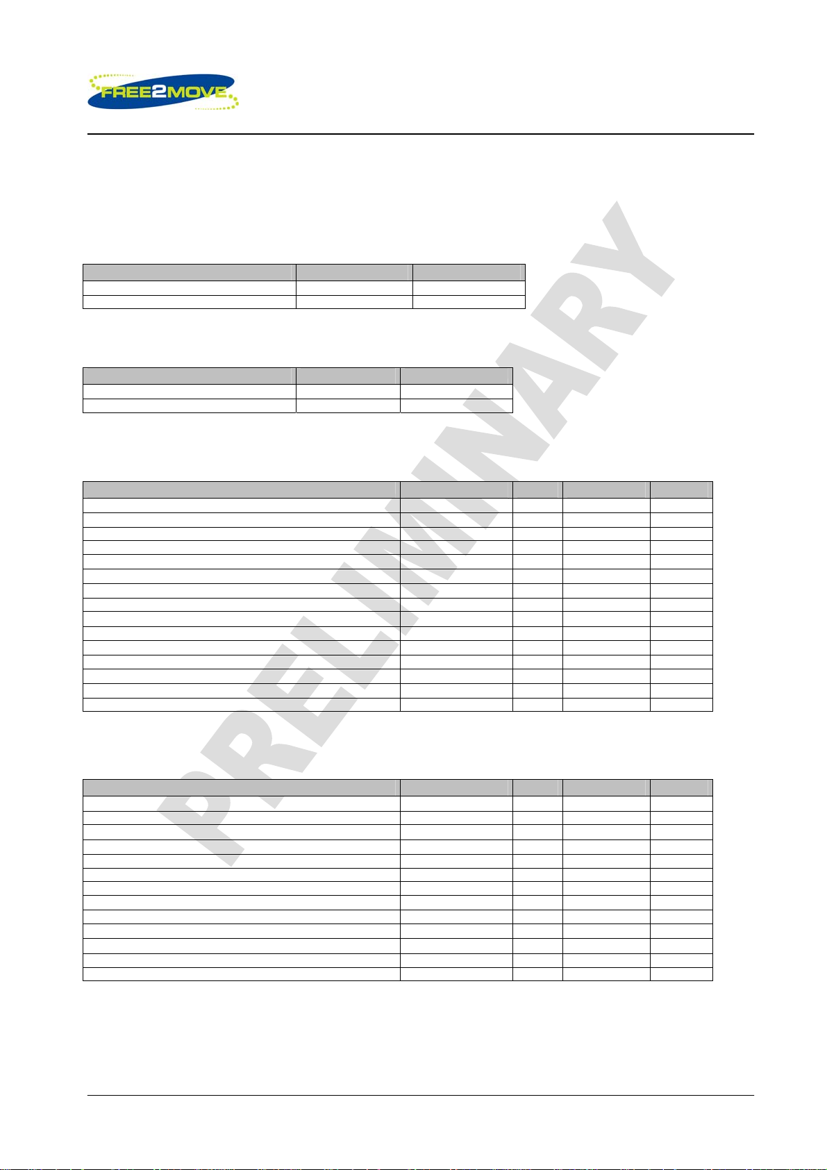
2 Device terminal functions
Power supply Pin Pin type Description
GND 7, 13, 33, 34,
35
NC 36,37,38,39 NC Not connected, connect to unconnected
VDD 12 VDD Supply voltage 2.3V to 3.5V
Analog I/O Pin Pin type Description
AUX_DAC 5
AIO(0) 6 Bi-directional Programmable input/output line
Test and debug Pin Pin type Description
RESET 28 CMOS input with weak internal pull-up Reset if low. Input debounced so must be
SPI_MISO 26 CMOS output, tristatable with weak internal
SPI_CSB 25 CMOS input with weak internal pull-up Chip select for Synchronous Serial
SPI_CLK 24 CMOS input with weak internal pull-down Serial Peripheral Interface clock
SPI_MOSI 27 CMOS input with weak internal pull-down Serial Peripheral Interface data input
UART Pin Pin type Description
UART_CTS 11 CMOS input with weak internal pull-down UART clear to send active low
UART_TX 10 CMOS output UART data output active high
UART_RTS 8 CMOS output, tristatable with internal pull-up UART request to send active low
UART_RX 9 CMOS input with weak internal pull-down UART data input active high
PCM Pin Pin type Description
PCM_OUT 19 CMOS output, tristatable with weak internal
PCM_SYNC 17 Bi-directional with weak internal pull-down Synchronous data sync
PCM_IN 18 CMOS input, with weak internal pull-down Synchronous data input
PCM_CLK 16 Bi-directional with weak internal pull-down Synchronous data clock
USB Pin Pin type Description
USB_D+ 14 Bi-directional
USB_D- 15 Bi-directional USB data minus
PIO Pin Pin type Description
PIO(2) 31
PIO(3) 30
PIO(4) 23
PIO(5) 22
PIO(6) 20
PIO(7) 21
PIO(8) 29
PIO(9) 32
Analog Audio Pin Pin type Description
MIC+ 4 Analogue input Microphone input positive
MIC- 3 Analogue input Microphone input negative
SPKR+ 2 Analogue output Speaker output positive
SPKR- 1 Analogue output Speaker output negative
VSS Ground connections
pads to ensure mechanical robustness
Analogue
pull-down
weak pull down
Voltage DAC output
low for >5ms to cause a reset
Serial Peripheral Interface data output
Interface active low
Synchronous data output
USB data plus with selectable internal
Bi-directional with programmable strength
internal pull-up/down
n
Bi-directional with programmable strength
internal pull-up/down
n
Bi-directional with programmable strength
internal pull-up/down
n
Bi-directional with programmable strength
internal pull-up/down
n
Bi-directional with programmable strength
internal pull-up/down
n
Bi-directional with programmable strength
internal pull-up/down
n
Bi-directional with programmable strength
internal pull-up/down
n
Bi-directional with programmable strength
internal pull-up/down
n
1_5k Q pull-up resistor
PIO
PIO
PIO
PIO
PIO
PIO
PIO
PIO
© 2007 Free2move AB
Page 4(4)
Low power Audio Bluetooth™ Module with antenna F2M03ALA
Preliminary datasheet
3 Electrical Characteristics
Absolute Maximum Ratings
Rating Min Max
Storage Temperature
Breakdown supply voltage -0.4V 5.60V
Recommended Operating Conditions*
-40°C +105°C
Rev: 0
Rating
Operating temperature range
Supply voltage 2.2V 4.2V
*F2M03ALA meet the Bluetooth v2.0+EDR specification when used in the recommended operating condition.
Min
-40°C +85°C
Max
Digital Terminals
Digital Terminals Min Typ Max Unit
Input Voltage
VIL input logic level low, 2.7V ≤ VDD ≤ 3.0V
VIH input logic level high 0.7VDD - VDD+0.4 V
Output Voltage
VOL output logic level low, (lO = 4.0mA), 2.7V ≤ VDD ≤ 3.0V
VOH output logic level high, (lO = 4.0mA), 2.7V ≤ VDD ≤ 3.0V
Input and tristate current
Strong pull-up -100 -40 -10
Strong pull-down +10 +40 +100
Weak pull-up -5.0 -1.0 -0.2
Weak pull-down +0.2 +1.0 +5.0
I/O pad leakage current -1 0 +1
CI Input Capacitance 1.0 - 5.0 pF
-0.4 - +0.8 V
- - 0.2 V
VDD-0.2 - - V
µA
µA
µA
µA
µA
USB Terminals
USB Terminals Min Typ Max Unit
USB Terminals
VDD for correct USB operation 3.1 - 3.6 V
Input threshold
VIL input logic level low - - 0.3VDD V
VIH input logic level high 0.7VDD - - V
Input leakage current
CI Input capacitance 2.5 - 10.0 pF
Output levels to correctly terminated USB Cable
VOL output logic level low 0 - 0.2 V
VOH output logic level high 2.8 - VDD V
© 2007 Free2move AB
Page 5(5)

Rev: 0
Low power Audio Bluetooth™ Module with antenna F2M03ALA
Preliminary datasheet
Auxiliary ADC
Auxiliary ADC, 8-bit resolution Min Typ Max Unit
Resolution
Input voltage range
(LSB size = 1.8/255= 7.1mV)
(Guaranteed monotonic)
Offset -1 - 1 LSB
Gain Error -0.8 - 0.8 %
Input Bandwidth - 100 - KHz
Conversion time - 2.5 - µS
Sample rate*
INL -1 - 1 LSB Accuracy
DNL 0 - 1 LSB
- - 8 Bits
0 - 1.8 V
- - 700 Sample/s
*The ADC is accessed through the VM function. The sample rate given is achieved as a part of this function
Auxiliary DAC
Auxiliary DAC, 8-bit resolution Min Typ Max Unit
Resolution - - 8 Bits
Average output step size 12.5 14.5 17.0 mV
Output Voltage Monotonic
Voltage range (IO=0mA) 0 - VDD V
Current range -10.0 - +0.1 mA
Minimum output voltage (IO=100µΑ)
Maximum output voltage (IO=10mA)
High impedance leakage current -1 - +1
Offset -220 - +120 MV
Integral non-linearity -2 - +2 LSB
Settling time (50pF load) - - 10
Notes:
Current drawn into a pin is defined as positive; current supplied out of a pin is defined as negative.
0 - 0.2 V
VDD-0.3 - VDD V
µA
µS
Audio CODEC
Audio CODEC, 15-Bit Resolution
(MIC and SPKR pins)
Microphone Amplifier
Input full scale at maximum gain - 3 - mV rms
Input full scale at minimum gain - 350 - mV rms
Gain resolution 2.8 3 3.2 dB
Gain range 42 - dB
Distortion at 1kHz - - -78 dB
Bandwidth - 20 - kHz
Input Impedance (Microphone input) - 20 Input Impedance (Line input) - 130 Analogue to Digital Converter
Input sample rate - 1 Output sample rate - 8 Distortion and noise at 1kHz (relative to full scale) - -78 -75 dB
Digital to Analogue Converter
Gain resolution 2.8 3 3.2 dB
Min gain - -18 - dB
Max gain - 3 - dB
Speaker Driver
Output voltage full scale swing (differential) - 2.0 - V Pk-Pk
Output current drive (at full scale swing) 10 20 40 mA
Output full scale current (at reduced swing) - 75 - mA
Output –3dB bandwith - 18.5 - kHz
Distortion and noise (relative to full scale) (32Ω load)
differential
Allowed load: resistive 8 - OC
Allowed load: capacitive - - 500 pF
Min Typ Max Unit
kΩ
kΩ
Msamples/s
KSamples/s
- -75 - dB
Ω
© 2007 Free2move AB
Page 6(6)
Low power Audio Bluetooth™ Module with antenna F2M03ALA
Preliminary datasheet
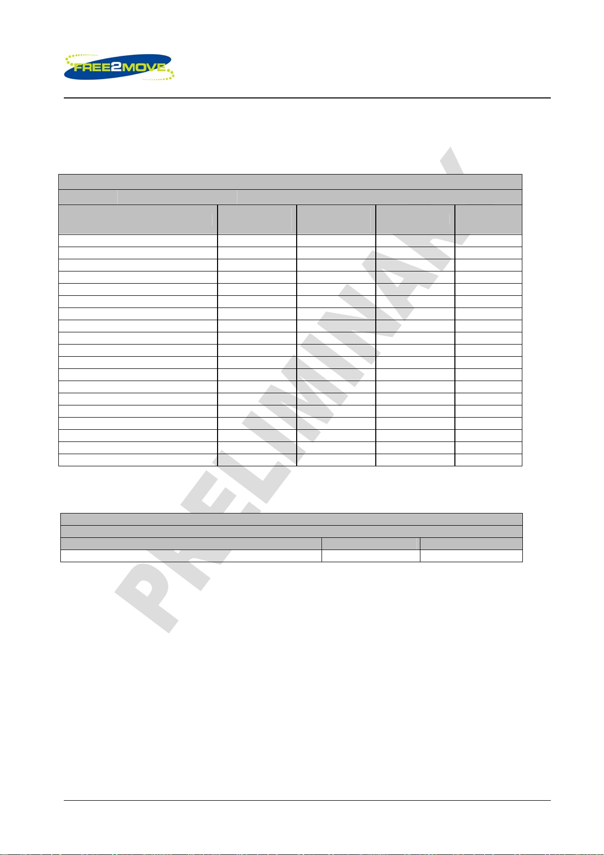
3.1 Power Consumption
Typical Average Current Consumption
VDD=3.1V Temperature = +20°C Output Power = 0dBm
Operation Mode
Page scan - 115.2 0.49 mA
Inquiry and page scan - 115.2 0.83 mA
ACL No traffic Master 115.2 4.1 mA
ACL With file transfer Master 115.2 12 mA
ACL No traffic Slave 115.2 17 mA
ACL With file transfer Slave 115.2 21 mA
ACL 40ms sniff Master 38.4 2.4 mA
ACL 1.28s sniff Master 38.4 0.37 mA
SCO HV1 Master 38.4 41 mA
SCO HV3 Master 38.4 21 mA
SCO HV3 30ms sniff Master 38.4 20 mA
ACL 40ms sniff Slave 38.4 2.1 mA
ACL 1.28s sniff Slave 38.4 0.42 mA
Parked 1.28s beacon Slave 38.4 0.20 mA
SCO HV1 Slave 38.4 41 mA
SCO HV3 Slave 38.4 26 mA
SCO HV3 30ms sniff Slave 38.4 20 mA
Standby Host connection - 38.4 76 µA
Reset (RESETB low) - - 58 µA
Connection
Type
Peak current consumption
VDD=3.1V Temperature = +20°C Output Power (max)= 4dBm
Mode Typ Unit
Peak consumption during RF peaks 75 mA
UART Rate
(kbps)
Average Unit
Rev: 0
© 2007 Free2move AB
Page 7(7)
Rev: 0
Low power Audio Bluetooth™ Module with antenna F2M03ALA
Preliminary datasheet
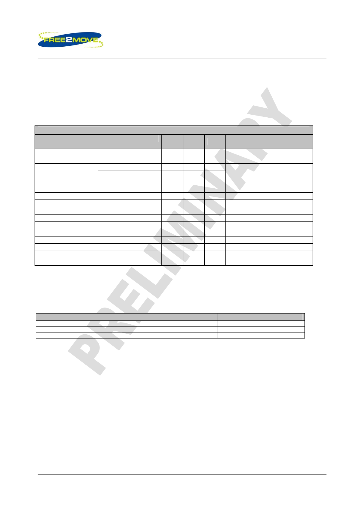
4 Radio Characteristics
VDD = 3.3V Temperature = 20 oC Frequency = 2.441GHz
All measurements are based on the Bluetooth test specification.
Radio Characteristics VDD = 3.3V Temperature = +25°C
Operating frequency
Maximum RF transmit power
Frequency (GHz)
Sensitivity at 0.1% BER
RF power control range
RF power range control resolution - 4 -
20dB bandwidth for modulated carrier - TBD -
∆f1avg .Maximum Modulation. - TBD
∆f2max .Minimum Modulation. - TBD -
∆f1avg/∆f2avg - TBD -
Initial carrier frequency tolerance - TBD -
Drift Rate - TBD -
Drift (single slot packet) - TBD -
Drift (five slot packet) - TBD -
2.402 - TBD -
2.441 - TBD -
2.480 - TBD -
Min Typ Max
2402 - 2480
- - 4
- TBD -
- 40<f1avg<175
Note:
The F2M03ALA has a maximum transmit power of +4dBm and is certified according to the Bluetooth
v2.0+EDR specification as a Class2 device. It is though possible to restrict the maximum transmit power to
comply with a Class3 device upon configuration.
Bluetooth Specification
Class of device Maximum transmit power
Class1 +20dBm
Class2 +4dBm
Class3 0dBm
Bluetooth
Specification
MHz
0 to 20 dBm
≤-70 dBm
≥16
-
≤1000
115
≥0.80
±75
≤20
≤25
≤40
Unit
dB
dB
kHz
-
kHz
KHz/50µs
kHz
kHz
© 2007 Free2move AB
Page 8(8)
Rev: 0
Low power Audio Bluetooth™ Module with antenna F2M03ALA
Preliminary datasheet
5 Firmware versions
F2M03 is supplied with Bluetooth stack firmware, which runs on the internal RISC micro controller of the
Bluetooth module. This chapter includes an overview of the different options for more in depth information
please use separate firmware datasheets provided by Free2move.
All firmware versions are compliant with the Bluetooth specification v2.0. The F2M03 software architecture
allows Bluetooth processing to be shared between the internal micro controller and a host processor.
Depending on application the upper layers of the Bluetooth stack (above HCI) can execute on-chip or on
the host processor.
Running the upper stack on F2M03 module reduces (or eliminates, in the case of a on module application)
the need for host-side software and processing time.
The integration approach depends on the type of product being developed. For example, performance will
depend on the integration approach adopted. In general Free2move offers four categories of Bluetooth
stack firmware:
• Wireless UART; offers a transparent UART interface to the Bluetooth channel. There is no need for
additional drivers or Bluetooth software on the host.
• Embedded module solutions offer an application to run on the module. There is no need for an
external host (E.g. a Bluetooth headset).
• Two-processor solution involving a host and host controller, where the higher layers of the
Bluetooth stack has to be implemented on the host.
• Two-processor embedded solution offers a host with limited resources to gain access to a
Bluetooth stack, with the higher layers on-chip, via a special API.
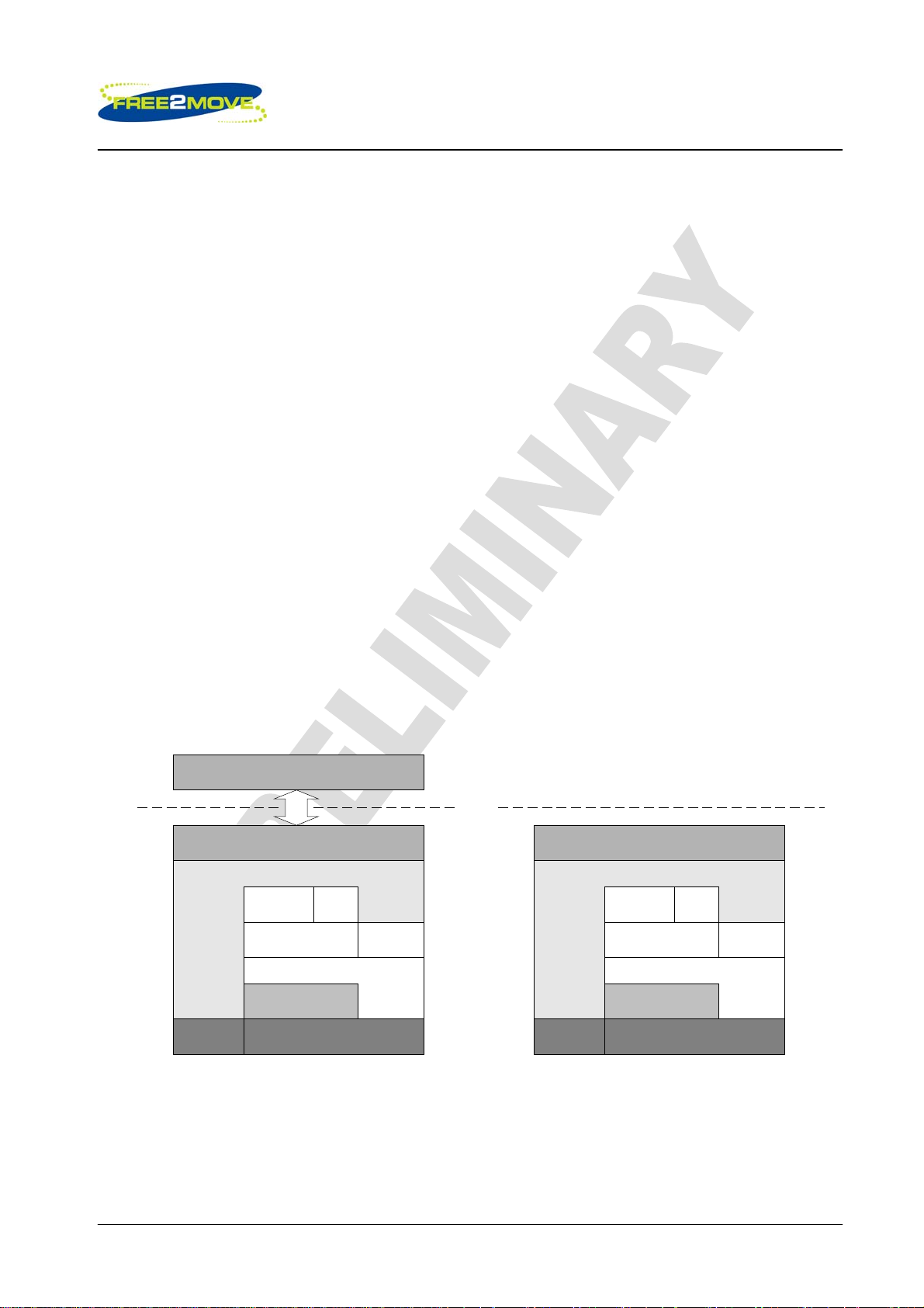
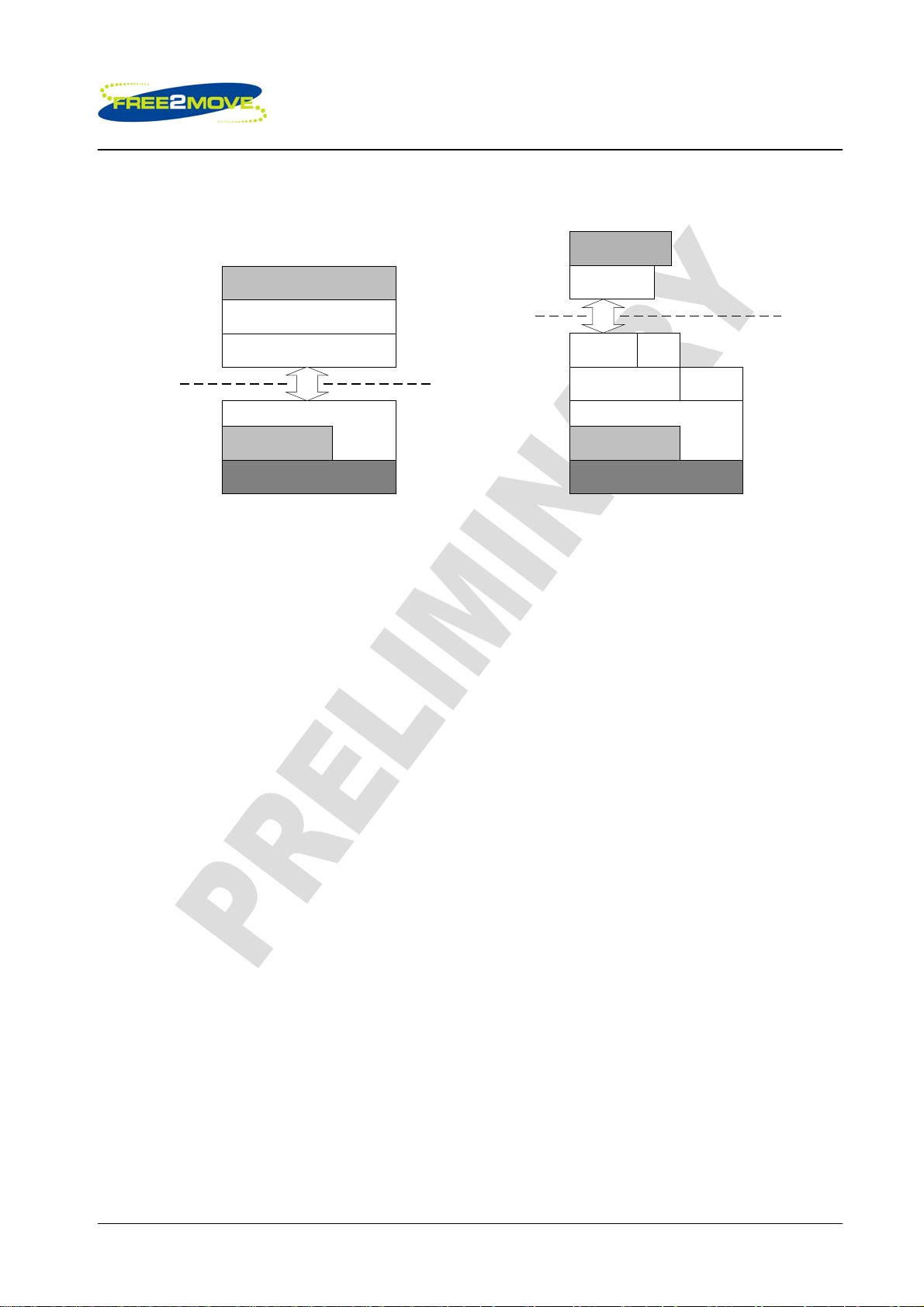
The protocol layer models for the different Bluetooth stack firmware categories can be represented as
shown in the figures below.
Host
F2M03
Application
Wireless UART application (SPP)
APPLICATION INTERFACE
RFCOMM SDP
L2CAP
HCI
LINK MANAGER
Hardware BASEBAND and RF
Wireless UART Embedded single-
Device
Manager
Host
F2M03
Application
APPLICATION INTERFACE
RFCOMM SDP
L2CAP
HCI
LINK MANAGER
Hardware BASEBAND and RF
processor architecture
Device
Manager
© 2007 Free2move AB
Page 9(9)
Rev: 0
Low power Audio Bluetooth™ Module with antenna F2M03ALA
Preliminary datasheet
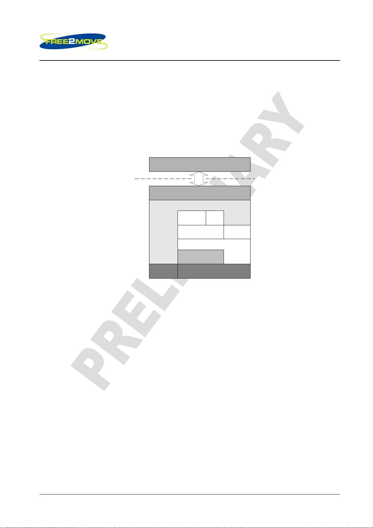
Application
Port Entity
RFCOMM SDP
L2CAP
HCI
LINK MANAGER
BASEBAND and RF
Device
Manager
Host
F2M03
Application
Bluetooth stack
HCI
HCI
LINK MANAGER
BASEBAND and RF
Host
F2M03
HCI, (Two-Processor
Architecture)
RFCOMM, (Embedded
Two-Processor Architecture)
Wireless UART
Free2move’s Wireless UART (WU) firmware is intended to replace the serial cable(s) connecting portable
and/or fixed electronic devices. Key features are robustness, high configurability, high security, low
complexity and low power. The WU firmware is compliant with the Bluetooth Serial Port Profile (SPP) for
setting up emulated serial cable connections between connected devices. There is no additional need for
drivers or an external host with Bluetooth software when using the WU firmware. When a successful
Bluetooth connection is established the data channel and the voice channel can be used simultaneously or
separately. All information sent/received at the data/voice interface of the WU unit is exchanged
transparently via Bluetooth with the connected remote device.
HCI (Standard Two-Processor Solution)
For the standard two-processor solution, where the split between higher and lower layers of the stack takes
place at the HCI, a complete Bluetooth stack is needed in the external host. It is often preferable to use this
solution when the host is a personal computer of some description. However, in general this category can
include any computing platform with communications capability that is not resource limited.
Free2move do not offer the host stack.
Embedded Solution
This version of the stack firmware requires no host processor. All software layers, including application
software, run on the internal RISC processor in a protected user software execution environment.
The embedded solution can be used for a single chip Bluetooth product. One example is a cordless
headset. However this solution is equally applicable to any small wireless device that would benefit from a
single processor solution.
Free2move can offers among others the following single chip solutions upon a custom request*:
• Headset / Hands Free
• Human Interface Device; Mouse, keyboard etc (HID)
• Dial Up Network (DUN)
• Audio Gateway Profile (AGP)
• OBEX
• Onboard application (development of customer specific applications)
*Please consult your reseller for more information about custom firmwares.
© 2007 Free2move AB
Page 10(10)
Rev: 0
Low power Audio Bluetooth™ Module with antenna F2M03ALA
Preliminary datasheet
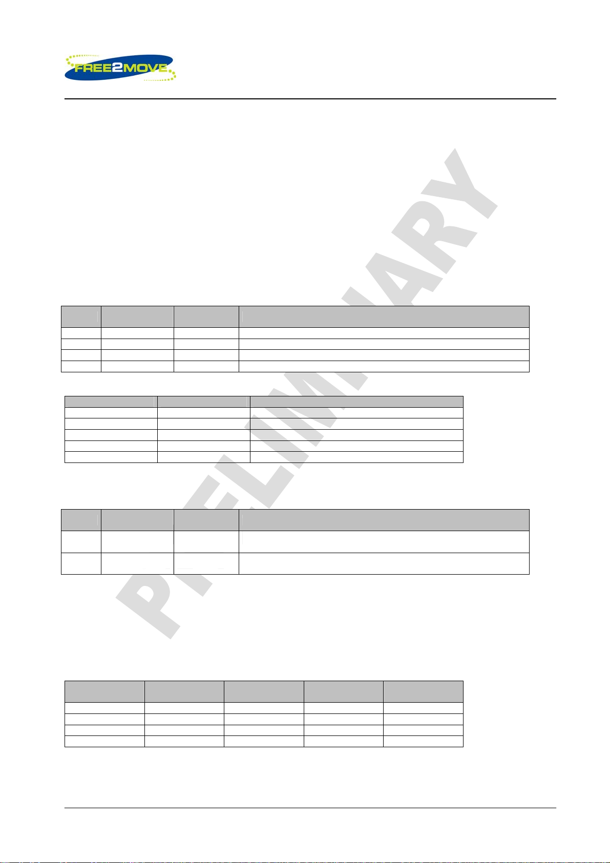
5.1 Wireless UART
Free2move’s Wireless UART (WU) firmware is intended to replace the serial cable(s) connecting portable
and/or fixed electronic devices. Key features are robustness, high configurability, high security, low
complexity and low power.
The WU firmware is compliant with the Bluetooth Serial Port Profile (SPP) for setting up emulated serial
cable connections between connected devices. There is no additional need for drivers or an external host
with Bluetooth software when using the WU firmware.
Host
F2M03
Wireless UART application (SPP)
APPLICATION INTERFACE
Hardware BASEBAND and RF
Application
RFCOMM SDP
L2CAP
HCI
LINK MANAGER
Device
Manager
Wireless UART architecture
The WU application runs on top of an embedded Bluetooth v2.0 + EDR compliant stack, including protocols
up to the RFCOMM layer. Point-to-point connections are supported. This means that a unit running WU can
be either a master or slave unit.
The WU firmware offers one asynchronous data channel and one synchronous voice channel, both
channels capable of full duplex transmissions.
When a successful Bluetooth connection is established the data channel and the voice channel can be
used simultaneously or separately. All information sent/received at the data/voice interface of the WU unit is
exchanged transparently via Bluetooth with the connected remote device.
The WU unit is set to operate in a default mode that allows the user to communicate via the asynchronous
data channel over Bluetooth, as soon as a successful connection has been established. This can be
achieved without sending any configuration commands to the WU firmware. However, as long as there is
no Bluetooth connection established, it is possible to configure the WU firmware via hex commands
(described in the document Wireless_UART_protocol) or using a Windows configuration software.
© 2007 Free2move AB
Page 11(11)
Rev: 0
Low power Audio Bluetooth™ Module with antenna F2M03ALA
Preliminary datasheet
5.1.1 General I/O
General I/O interfaces are used for different purposes between the WU firmware and the Host:
• Asynchronous data interface – configuration of the WU firmware or exchange transparent digital
information between the connected Bluetooth devices.
• Synchronous voice interface – exchange transparent voice information between the connected
Bluetooth devices.
• Bluetooth connectivity PIO interfaces – indication and disconnection of the established Bluetooth
connection.
• Emulate serial handshaking PIO lines interface – DTE or DCE serial handshake emulation between
the connected Bluetooth devices.
UART interface (Asynchronous data and configuration):
UART
TX Output High UART transmit data
RX Input High UART receive data
RTS Output Low UART request to send
CTS Input Low UART clear to send
Voice interface:
CODEC I/O Signal Direction Description
AUX_DAC Output (analogue) Microphone input bias
PIOs are used to control/monitor the Bluetooth connectivity of the WU firmware.
PIO
2 Input High
3 Output High
To prevent connections or to close the current Bluetooth connection PIO[2] can be set high.
PIO[3] is held low as long as there is no Bluetooth connection. As soon as a successful Bluetooth
connection has been established with a remote device, PIO[3] goes high.
PIOs can also be used to emulate serial handshaking lines between the connected Bluetooth devices.
Emulation can either be DTE or DCE.
Emulated Signal PIO Signal Direction
While the handshaking lines are transparent to the data channel these I/O may also be used to transfer
digital signals between two Free2move devices running WU
Signal
Direction
MIC_P Input (analogue) Microphone input positive
MIC_N Input (analogue) Microphone input negative
SPKR_P Output (analogue) Speaker output positive
SPKR_N Output (analogue) Speaker output negative
Signal
Direction
RI 4 Input Output High
DTR 5 Output Input High
DCD 6 Input Output High
DSR 7 Input Output High
Active (TTL) Description
Active (TTL) Description
Request to close the current Bluetooth connection to the remote
device.
Indicates that a successful Bluetooth connection is established with a
remote device.
Emulate DTE
Signal Direction
Emulate DCE
Active (TTL)
© 2007 Free2move AB
Page 12(12)
Rev: 0
Low power Audio Bluetooth™ Module with antenna F2M03ALA
Preliminary datasheet
5.1.2 Settings
The default settings allow the user to communicate via Bluetooth, without sending any configuration
commands, as soon as a successful connection has been established. Information sent and received on
the serial interface of the WU unit at 38400 bps is transmitted transparently between the two connected
devices. The default settings are valid as long as the user has made no configuration.
When there is no Bluetooth connection established it is possible to configure the WU firmware via
commands sent on the serial interface. All settings changed by the user are stored in persistent memory.
The following serial settings are used for configuration mode and are not configurable:
Parameter Default Value
Baud rate 38400
Data bits 8
Parity None
Stop bits 1
Hardware flow control On
To be able to send commands to the Wireless UART firmware, it must be set in Host Controlled Mode
(HCM). As previously described the Wireless UART firmware can only enter HCM when no Bluetooth
connection is established.
Once entered HCM there are several commands that can be issued:
• Configuration commands
• Software / Hardware reboot
• Inquiry (search for Bluetooth devices in the neighborhood)
• Pairing (device security - authentication and encryption)
• Advanced configuration commands
• SCO commands
• Information commands
• Control commands
Configuration Commands
There are several settings stored in the Wireless UART firmware that can be read and modified by using
the configuration commands.
Examples of these settings are:
• Local Bluetooth name
• Local SDP-service name
• Operating mode
• Serial port settings
• Bluetooth security settings (authentication, encryption)
There are two normal operating modes:
• Connecting mode – Bluetooth master
• Endpoint mode – Bluetooth slave
In Connecting mode the Wireless UART firmware will continuously try to establish a Bluetooth connection to
a specified remote Bluetooth device in the neighborhood (Bluetooth master).
In Endpoint mode the Wireless UART firmware may accept connections from remote Bluetooth devices. A
connection request will be accepted when the specified rules are fulfilled (Bluetooth slave).
© 2007 Free2move AB
Page 13(13)

Rev: 0
Low power Audio Bluetooth™ Module with antenna F2M03ALA
Preliminary datasheet
Software / Hardware Reboot
This option gives the ability to be able to reboot the module via software commands.
Inquiry
Search for other Bluetooth devices in the neighborhood.
There are three configuration parameters:
• How many seconds the search should be active
• A filter, used when searching for devices of as certain class
• The possibility to include the Bluetooth name of the discovered devices
Pairing
When authentication is enabled, the devices must be paired before a successful connection can be
established.
The Wireless UART firmware can either initiate pairing with a remote device or accept pairing requests.
During a pairing PIN codes are exchanged between the local and remote device. A successful pairing
requires identical PIN codes. The result of the pairing attempt will be returned to the Host. If pairing was
successful, a unique link key has been generated and saved in non-volatile memory. The link key is used in
the connection establishment procedure for secure verification of the relationship between the paired
devices.
The Wireless UART firmware allows the user to be paired with one device at a time. The last pin code
entered and link key generated are saved.
Advanced configuration
Includes among others commands for enabling power save modes, fine tune performance, enabling
modem emulation and changing transmit power.
SCO commands
Makes it possible to establish full duplex audio connections between two WU units.
© 2007 Free2move AB
Page 14(14)

Rev: 0
Low power Audio Bluetooth™ Module with antenna F2M03ALA
Preliminary datasheet
5.1.3 Performance
The WU firmware is a complete on-chip application; limited resources restrict the maximum throughput. The
table below shows the maximum achieved throughput when streaming data between two connected WU
v4.00 devices at close range.
Maximum
Direction Baud Rate
Master to Slave 57600 ~57.6 ~57.6
Slave to Master 57600 ~57.6 ~57.6
Full duplex 57600 ~57.6 ~50.5
Master to Slave 115200 ~115.1 ~93.9
Slave to Master 115200 ~115.1 ~79.6
Full duplex 115200 ~114.5 ~42.0
Master to Slave 230400 ~223.1 ~158.0
Slave to Master 230400 ~221.4 ~117.7
Full duplex 230400 ~172.7 ~86.2
Master to Slave 460800 ~228.6 ~206.7
Slave to Master 460800 ~222.7 ~154.1
Full duplex 460800 ~173.3 ~109.8
Master to Slave 921600 ~240.1 ~235.7
Slave to Master 921600 ~235.4 ~186.0
Full duplex 921600 ~174.7 ~150.5
Throughput (kbit/s
(throughput mode))
Maximum
Throughput (kbit/s)
(latency mode)
5.1.4 Configuration
The F2M03 can either be configured using hex commands described in the document
“Wireless_UART_protocol.pdf” or using the Windows configuration software. The configuration software
can be downloaded from
www.free2move.net
© 2007 Free2move AB
Page 15(15)
 Loading...