

Page 1
Assembly Instructions
Item No. FR30106
T24 JA8-2016
Les Instructions D’assemblage
Numéro d’article: FR30106
Instrucciones De Montaje
{ DRAWING 1 }
Número del artículo: FR30106
start here
1. Find a clear area in which you can work.
2. Unpack fixture from carton.
3. Carefully review instructions prior to assembly.
*** The construction of this fixture will be accomplished by first
assembling the main body of the fixture, making all necessary electrical
connections, hanging the fixture from the ceiling and then installing
the fixture glass.
Note: It will be necessary to determine the length of rods you will
require to hang your fixture at the desired height. After this has
been established, please follow the instructions below.
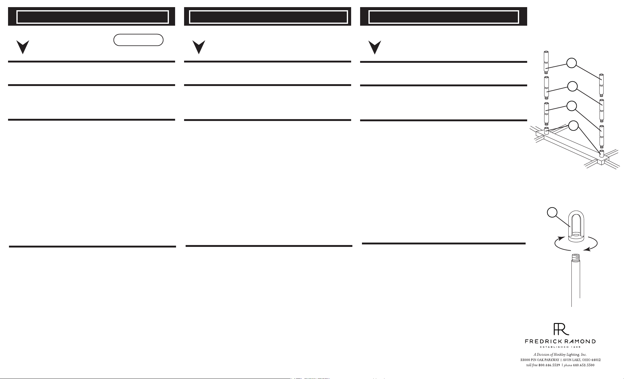
1. Slip first rod section (B) along wire and thread into top of main fixture
body (A) .
2. Slip next section of rod (C) along wire and thread into previously
installed rod – see Drawing 1 .
3. Continue adding sections of rod until all necessary length have been
attached to the fixture.
4. After last stem is installed remove loop
chain link. Remove loop and thread onto top of stem. Now hook loop
back onto chain link and close link - see Drawing 2 .
5. Fixture can now be mounted to the ceiling by following mounting
instruction sheet (FR30106) provided.
(L) from canopy by opening
commencez ici
1. Trouvez un espave libre dans le quel vous pouvez travailler.
2. Déballlez appareil de la boîte.
3. Examinez attentivement les instructions avant le montage.
*** La construction de ce dispositif sera réalisé selon la première de
montage de la bride de montage de la boîte de jonction, toutes les
connexions électriques nécessaires, l’assemblage du corps principal du
dispositif de fixation, le montage de la fixation à la paroi, puis
l’installation du verre.
Remarque: Il sera nécessaire de determiner la longueur des tiges don’t
1. Slip première section de tige (B) le long du fil et du fil dans le haut
du corps de l’appareil principal (A) .
2. Glissez la prochaine section de la tige (C) le long du fil et du fil dans
le haut de la tige déjà installé – Voir Schéma 1 .
3. Continuez à ajouter des sections de tige jusqu’à ce que toute la
longueur nécessaire a été fixé à l’appareil.
4. Después de instalar el último vástago, retire el lazo (L) del dosel
abriendo el eslabón de la cadena. Retire el lazo y el hilo en la parte
superior del vástago. Ahora vuelva a enganchar el lazo en el
eslabón de la cadena y cierre el acoplamiento - vea Dibujo 2.
5. Appareil peut maintenant être monté au plafond en suivant notice
de montage (FR30106) fourni.
vous aurez besoin pour accrocher votre projecteur à la
hauteur souhaitée. Après cela a été établi, s’il vous plaît
suivez les instructions ci-dessous.
empezar aquí
1. Busque un lugar claro en el que se puede trabajar.
2. Desembale accesorio de la caja.
3. Revise cuidadosamente la In strucciones antes del montaje.
*** La construcción de este dispositivo se logra mediante el montaje de
la primera correa de montaje a la caja de conexiones, por lo que todas
las conexiones eléctricas necesarias, el montaje del cuerpo principal del
dispositivo de fijación, el accesorio de montaje a la pared, y luego
instalar el cristal.
Nota: Será necesario determiner la longitude de las barras que se
requieren para colgar su parato a la altura deseada. Después
de esto se ha establecido, por favor, siga las siguientes
instrucciones.
1. Deslice primera sección de la barra (B) a lo largo del alambre e hilo
en la parte superior del cuerpo principal del aparato (A) .
2. Deslice siguiente sección de la varilla (C) a lo largo del alambre e
hilo en la parte superior de la barra instalada anteriormente –
Véase la Figura 1 .
3. Continúe agregando secciones de varrilla hasta que todas la
longitude necesaria se han unido a la luminaria.
4. Después de instalar el último vástago, retire el lazo (L) del dosel
abriendo el eslabón de la cadena. Retire el lazo y el hilo en la parte
superior del vástago. Ahora vuelva a enganchar el lazo en el eslabón
de la cadena y cierre el acoplamiento - vea Dibujo 2 .
4. Aparato ahora se puede montar en el techo siguiendo montaje hoja
de Instrucciones (FR30106) proporcionado.
C
C
B
A
{ DRAWING 2 }
L
1. After fixture is installed it can be lamped accordingly.
1. Después de instalar luminaria se puede lamped consecuencia.
1. Après appareil est installé, il peut être lamped conséquence.
Page 2
mounting instruction FR 30106 FR 30106 de montaje de instrucciones Instruction de montage FR 30106
english spanish french
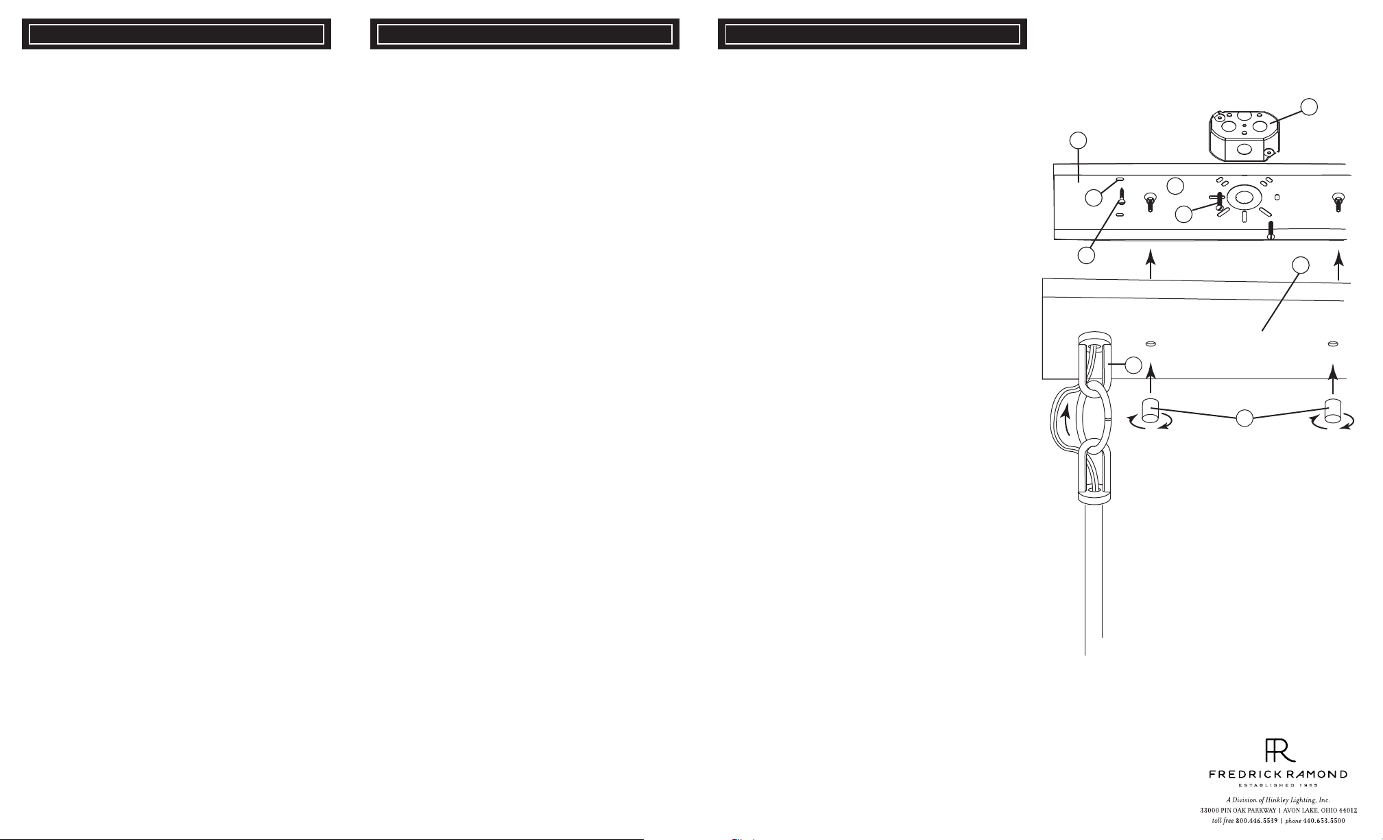
1. To begin installation of your fixture first attach the mounting
plate (a) to the junction box (j). This is accomplished by first,
threading barrel knobs (b) off of screws (s) in mounting plate (a)
that hold the mounting plate (a) to the canopy (c) - see Drawing 1.
2. Remove mounting plate from canopy and remove the appropriate knock outs to allow the mounting plate to be attached to
junction box, using screws (d) NOT PROVIDED.
3. NOTE: additional anchor (x) can be used and are recommended. They can be installed through holes (e) of the mounting plate
(a). Use appropriate anchors for the material you are anchoring
too.
4. Next assembly fixture per instruction sheets provided. Return
to this page, to complete the installation of your fixture. to this
page, to complete the installation of your fixture.
SAFETY WARNING: READ WIRING AND GROUNDING
INSTRUCTIONS (I.S. 18) AND ANY ADDITIONAL DIRECTIONS. TURN POWER SUPPLY OFF DURING INSTALLATION. IF NEW WIRING IS REQUIRED, CONSULT A QUALIFIED ELECTRICIAN OR LOCAL AUTHORITIES FOR CODE
REQUIREMENTS.
Make electrical connections from supply wire to fixture lead
wires. Refer to instruction sheet (I.S. 18) and follow all
instructions to make all necessary wiring connections. Then
refer back to this sheet to complete installation of this
1. After stems and loop is attached to canopy, feed wire through
center hole in loop (g) on canopy.
2. Now make all elecrical connections following instruction sheet
FRIS-18 provided.
3. Now slip mounting screws (s) thropugh holes in the canopy (c)
and thread on barrel knobs (b) to secure fixture to ceiling.
Now follow glass panel installation instruction sheet provided to
complete assembly.
1. Para comenzar la instalación de su aparato, primero conecte la
placa de montaje (a) a la caja de conexiones (j). Esto se logra
primero, enhebrando las perillas del barril (b) de los tornillos de la
placa de montaje (a) que sujetan la placa de montaje (a) a la
cubierta (c) - vea el Dibujo 1.
2. Retire la placa de montaje de la cubierta y retire las muescas
apropiadas para permitir que la placa de montaje se fije a la caja
de empalme, utilizando tornillos (d) NO SUMINISTRADOS.
3. NOTA: se puede utilizar un anclaje adicional (x) y se recomiendan. Pueden instalarse a través de orificios (e) de la placa de
montaje (a). Utilice anclajes apropiados para el material que está
anclando también.
4. Ensamblaje siguiente de la asamblea por las hojas de
instrucción proporcionadas. Vuelva a esta página, para completar
la instalación de su dispositivo. A esta página, para completar la
instalación de su dispositivo.
ADVERTENCIA DE SEGURIDAD: LEA LAS INSTRUCCIONES
DE ENCENDIDO Y CONEXIÓN A TIERRA (I.S. 18) Y CUALQUIER DIRECCIÓN ADICIONAL. DESCONECTE LA FUENTE DE
ALIMENTACIÓN DURANTE LA INSTALACIÓN. SI SE REQUIERE NUEVO CABLEADO, CONSULTE A UN ELECTRICISTA
CALIFICADO O AUTORIDADES LOCALES PARA REQUISITOS
DE CÓDIGO.
Realice las conexiones eléctricas desde el cable de alimentación
hasta los conductores de instalación. Consulte la hoja de
instrucciones (I.S. 18) y siga todas las instrucciones para realizar
todas las conexiones de cableado necesarias. A continuación,
consulte esta hoja para completar la instalación de esta
instalación.
1. Después de colocar los vástagos y el lazo en el dosel,
alimentar el alambre a través del agujero central en el lazo (g) en
el dosel.
2. Ahora haga todas las conexiones eléctricas siguiendo la
instrucción FRIS-18 suministrada.
3. Ahora deslice los tornillos de montaje en los orificios de la
cúpula (c) e hilo en las perillas del cañón (b) para asegurar la
fijación al techo.
Ahora siga la hoja de instrucciones de instalación del panel de
vidrio suministrada para completar el montaje.
1. Pour commencer l'installation de votre appareil fixez d'abord la
plaque de montage (a) à la boîte de jonction (j). Pour ce faire, il
suffit d 'abord de visser les boulons (b) des vis dans la plaque de
montage (a) qui maintiennent la plaque de montage (a) sur la
verrière (c) - voir le schéma 1.
2. Retirez la plaque de montage de la verrière et retirez les
embouts appropriés pour permettre à la plaque de montage
d'être fixée à la boîte de jonction, à l'aide de vis (d) NON
FOURNIES.
3. REMARQUE: une ancre supplémentaire (x) peut être utilisée
et est recommandée. Ils peuvent être installés à travers les trous
(e) de la plaque de montage (a). Utilisez des ancres appropriées
pour le matériau que vous ancrez aussi.
4. Ensemble de montage suivant selon les instructions fournies.
Revenez sur cette page, pour terminer l'installation de votre
appareil. À cette page, pour terminer l'installation de votre
appareil.
AVERTISSEMENT DE SÉCURITÉ: LIRE LES INSTRUCTIONS
DE CÂBLAGE ET DE MISE À LA TERRE (I.S. 18) ET TOUTES
DIRECTIVES ADDITIONNELLES. ETEINDRE L 'ALIMENTATION LORS DE L' INSTALLATION. SI UN NOUVEAU
CABLAGE EST NÉCESSAIRE, CONSULTEZ UN ÉLECTRICIEN QUALIFIÉ OU LES AUTORITÉS LOCALES POUR LES
EXIGENCES DE CODE.
Effectuer des connexions électriques entre le fil d'alimentation et
les fils conducteurs de fi xture. Reportez-vous à la feuille
d'instructions (I.S. 18) et suivez toutes les instructions pour
effectuer toutes les connexions de câblage nécessaires.
Reportez-vous ensuite à cette fiche pour terminer l'installation de
cette luminaire.
1. Après avoir fixé les tiges et la boucle à la verrière, introduire le
fil dans le trou central dans la boucle (g) sur la verrière.
2. Effectuez toutes les connexions électriques conformément à la
notice FRIS-18 fournie.
3. Glissez maintenant les vis de montage (s) dans la canopée (c)
et enfilez-les sur les boutons (b) pour fixer le luminaire au
plafond.
Suivez maintenant la feuille d'instructions d'installation du
panneau de verre fourni pour compléter l'assemblage.
{DRAWING 1}
j
a
e
d
x
c
g
b
Page 3
Wiring Instructions for 0-10 volt LED dimmer
Instrucciones de cableado para atenuador LED de 0-10 voltios
Instructions de câblage pour gradateur LED 0-10 volts
DRAWING 1
DIMMER
start here
Your fixture is designed so it can use a standard incandescent
dimmer, Or a 0-10 volt LED dimmer. If a 0-10 volt LED dimmer is
used, it may be necessary to have additonal wiring installed from the
dimmer switch to the fixture. Consulting an electrician will be
necessary.
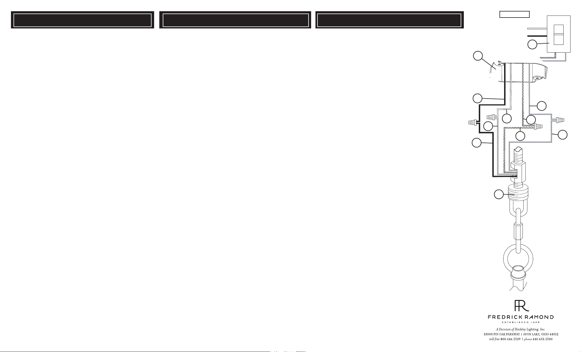
1. If using the optional 0-10 volt dimmer there will be four wires exiting
the junction box. (B) Black [+], (W) White [-], wirng are for the 120 /
277 voltage. The (G) Gray {-} and (P) Purple {+} are for the 0-10 volt
wires from the dimmer (D) - see Drawing 1.
2. The fixture has four wires of corrisponding colors. When make the
wire connections follow the chart below.
Black (B) from junction box (J) wired to Black (B) from fixture (F). White
(W) from junction box (J) wired to White (W) from fixture (F). Gray/
Pink(G) from junction box (J) wired to Gray/Pink (G) from fixture (F).
Purple (P) from junction box (J) wired to Purple (P) from fixture (F)
Connect ground wire from fixture to ground screw on mounting
hardware
INCANDESCENT DIMMER USAGE:
If using an incadescent dimmer follow manufactures instructions.
NOTE: MAKE SURE TO CAP OFF THE GRAY AND PURPLE
WIRE FROM THE FIXTURE INSIDE THE CANOPY. IF THE ARE
NOT CAPPED THEY CAN SHORT OUT AND CAUSE THE
FIXTURE TO FAIL.
empezar aquí
Su luminaria está diseñada para que pueda usar un atenuador
incandescente estándar o un atenuador LED de 0-10 voltios. Si se utiliza
un atenuador LED de 0-10 voltios, puede ser necesario instalar cableado
adicional desde el interruptor atenuador hasta la luminaria. Consultar a un
electricista será
1. Si usa el atenuador opcional de 0-10 voltios, habrá cuatro cables
saliendo de la caja de conexiones. (B) Negro [+], (W) Blanco [-], los
cables son para el voltaje 120/277. El (G) Gris {-} y (P) Morado {+} son
para los cables de 0-10 voltios del atenuador (D); consulte el Dibujo 1.
2. La luminaria tiene cuatro hilos de colores correspondientes. Al realizar
las conexiones de cables, siga la tabla a continuación.
Negro (B) de la caja de empalmes (J) cableado a Negro (B) del accesorio
(F).
Blanco (W) de la caja de empalmes (J) cableado a Blanco (W) del
accesorio (F).
Gris/Rosa (G) desde la caja de empalmes (J) cableado a Gris/Rosa (G)
desde la luminaria (F).
Púrpura (P) desde la caja de empalmes (J) cableado a Púrpura (P) desde
el accesorio (F)
Conecte el cable de tierra del dispositivo al tornillo de tierra en el
hardware de montaje
USO INCANDESCENTE DEL DIMMER:
Si usa un atenuador incadescente, siga las instrucciones del fabricante.
NOTA: ASEGÚRESE DE TAPAR EL CABLE GRIS Y PÚRPURA DE LA
LUMINARIA DENTRO DEL DOSEL. SI NO ESTÁN TAPADOS, CAUSAN
UN CORTOCIRCUITO Y LA LUMINARIA NO FUNCIONA.
commencez ici
Votre luminaire est conçu pour pouvoir utiliser un variateur à incandescence standard ou un variateur LED 0-10 volts. Si un gradateur LED
0-10 volts est utilisé, il peut être nécessaire d'avoir un câblage supplémentaire installé entre le variateur et le luminaire. Consulter un
électricien sera
1. Si vous utilisez le gradateur optionnel 0-10 volts, quatre fils sortent de
la boîte de jonction. (B) Noir [+], (W) Blanc [-], le câblage est pour la
tension 120/277. Les (G) Gray {-} et (P) Purple {+} sont pour les fils 0-10
volts du gradateur (D) - voir Schéma 1.
2. Le luminaire a quatre fils de couleurs correspondantes. Lorsque vous
effectuez les connexions des fils, suivez le tableau ci-dessous.
Negro (B) de la caja de empalmes (J) cableado a Negro (B) del
accesorio (F).
Blanco (W) de la caja de empalmes (J) cableado a Blanco (W) del
accesorio (F).
Gris/Rosa (G) desde la caja de empalmes (J) cableado a Gris/Rosa (G)
desde la luminaria (F).
Púrpura (P) desde la caja de empalmes (J) cableado a Púrpura (P)
desde el accesorio (F)
Conecte el cable de tierra del dispositivo al tornillo de tierra en el
hardware de montaje
UTILISATION INCANDESCENTE DU DIMMER:
Si vous utilisez un variateur à incandescence, suivez les instructions du
fabricant.
REMARQUE:
VIOLET DU LUMINAIRE À L'INTÉRIEUR DE L'AUVENT. S'ILS NE
SONT PAS PLAFONNÉS, ILS PROVOQUENT UN COURT-CIRCUIT ET
LE LUMINAIRE NE FONCTIONNE PAS.
ASSUREZ-VOUS DE COUVERCLE LE FIL GRIS ET
J
SUPPLY WIRES
FROM
JUNCTION BOX
B
W
B
D
SWITCH
WIRES FROM
DIMMER
G
W
P
P
G
F
Page 4

IS-SCC [safety cable installation]
IS-SCC [Instalación de cable de seguridad]
English Spanish
IS-SCC [installation de câbles de sécurité]
French
Drawing 1 -
ceiling
joist
Safety Cable Installatio
junction
box
n
2
1
WARNING: TO AVOID ELECTRICAL SHOCK, THIS SECTION
OF THE INSTRUCTION SHEET IS FOR THE SOLE PURPOSE
OF SAFETY CABLE INSTALLATION, AND IS NOT TO BE USED
TO MAKE ANY ELECTRICAL CONNECTIONS.
.
The safety cable must be attached to a ceiling joist or other
permanent structure independent of the junction box.
1. using a 3/16" dia. drill, drill a pilot hole (1). It must be drilled into the
permanent structure or through the junction box on the joist side
were the safety cable will be attached - see Drawing 1.
2. Insert and thread a 1/4" hex head lag screw (2) (not included) into
pilot hole.
3. Continue installation of this ÿxture according to IS19-50 provided.
4. After length of safety cable is determined, allow enough extra cable
so it can be wrapped around lag screw. Thread lag screw to secure
3
safety cable.
Make electrical connections from supply wire to fixture lead wires.
Refer to instruction sheet (I.S. 18) and follow all instructions to make
all necessary wiring connections. Then refer back to this sheet to
continue installatio of this fixture.
start here
ADVERTENCIA: PARA EVITAR CHOQUE ELÉCTRICO,
ESTA SECCIÓN DE LA HOJA DE INSTRUCCIONES
ES EL ÚNICO PROPÓSITO DE INSTALACIÓN DEL
CABLE DE SEGURIDAD, Y NO DEBE SER UTILIZADO
PARA REALIZAR LAS CONEXIONES ELÉCTRICAS.
.
El cable de seguridad debe estar conectada a una vigueta
de techo u otra estructura permanente independiente de la
caja de conexiones.
1. Utilizando un 3/16 "de diámetro. Taladro, perfore un
agujero piloto (1). Debe ser perforado en la estructura
permanente oa través de la caja de conexiones en el lado
de la vigueta se el cable de seguridad será adjunto
- ver dibujo 1.
2. Inserte y enrosque un tornillo de retraso de 1/4 "de
cabeza hexagonal (2) (no incluido) en el orificio piloto.
3. Continuar la instalación de este aparato de acuerdo con
IS19-50 proporcionado.
4. Después se determina la longitud de cable de seguridad,
deje suficiente cable adicional para que pueda ser
envuelta alrededor de tornillo de tracción. Tema tirafondo
para fijar el cable de seguridad.
Haga las conexiones eléctricas del cable de alimentación los
cables conductores del luminario. Consulte la hoja de instrucciones
(IS 18) y siga todas las instrucciones para hacer todas las
conexiones necesarias. Entonces referirse a esta hoja para
continuar instalacion de este luminario.
empezar aquí
AVERTISSEMENT: POUR ÉVITER UNE ÉLECTROCUTION,
CETTE SECTION DE LA FEUILLE D'INSTRUCTIONS EST
DANS LE SEUL BUT DE CÂBLE DE SÉCURITÉ
INSTALLATION, ET NE DOIT PAS ÊTRE UTILISÉ POUR
FAIRE LES CONNEXIONS ÉLECTRIQUES.
.
Le câble de sécurité doit être attaché à une solive du
plafond ou une autre structure permanente indépendante de
la boîte de jonction.
1. L'aide d'un foret de 3/16 "de diamètre., Percer un trou
pilote (1). Elle doit être foré dans la structure permanente ou
la boîte de jonction sur le côté solives ont le câble de sécurité
sera ci-joint - voir schéma 1.
2. Insérez et vissez une vis 1/4 "à tête hexagonale de retard
(2) (non inclus) dans le trou pilote.
3. Continuer l'installation de ce luminaire selon IS19-50 fourni.
4. Après longueur de câble de sécurité est déterminé,
prévoyez suffisamment de câble supplémentaire de sorte
qu'il peut être enroulé autour de la vis tire-fond. Sujet
décalage vis pour fixer le câble de sécurité.
Effectuer les connexions électriques du câble d'alimentation au
montage des fils conducteurs. Reportez-vous à la feuille d'instruction
(IS 18) et suivez les instructions pour faire toutes les connexions
nécessaires. Ensuite, se reporter à la fiche de continuer installatio
de ce luminaire.
commencez ici
 Loading...