

Page 1
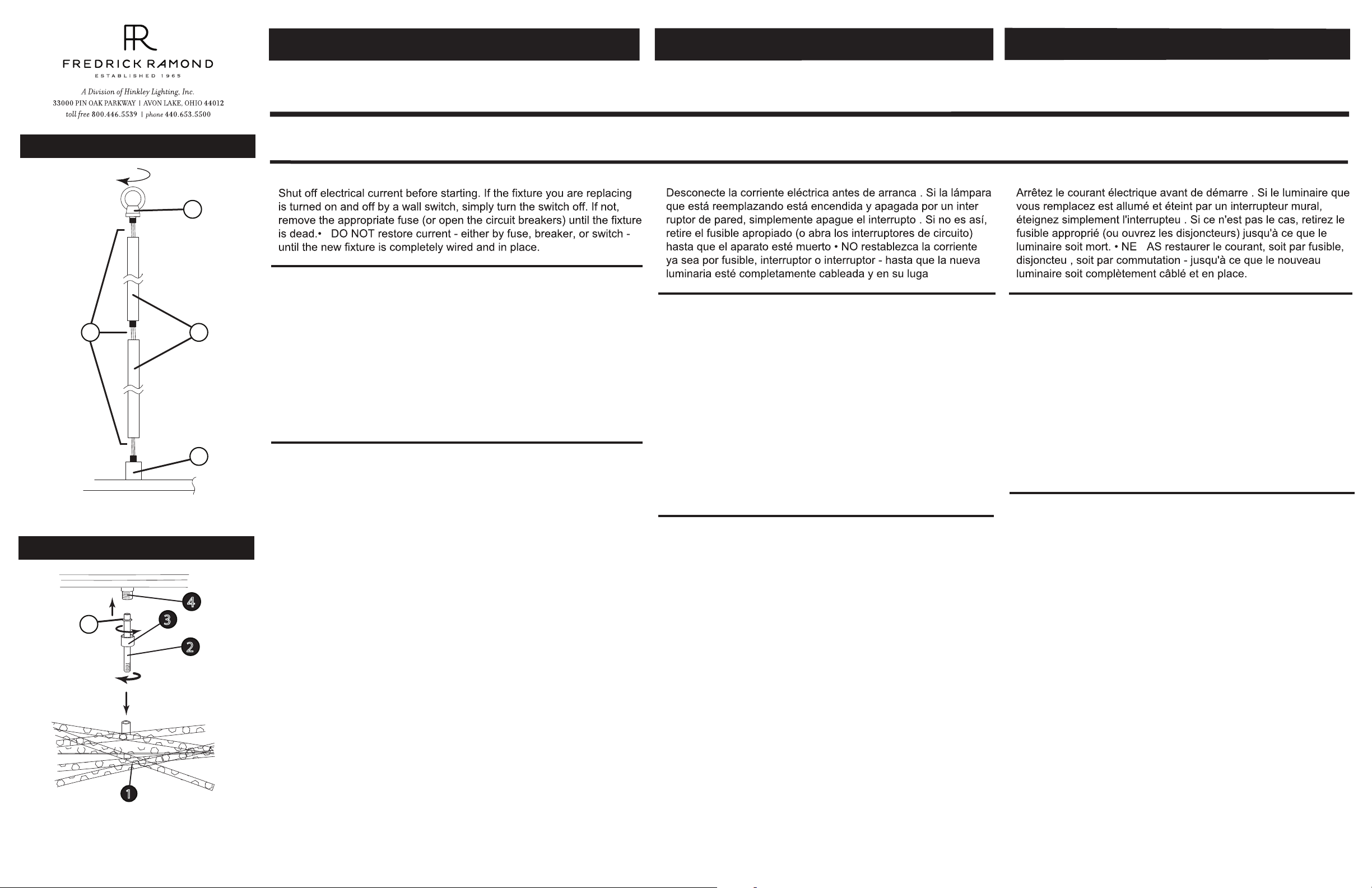
DRAWING 1 - ASSEMBLY
L
W
S
C
DRAWING 2 - ASSEMBLY
4
A
3
2
Item No: FR46407
1. Find a clear area in which you can work.
2. Unpack fixture and glass from carton.
3. Carefully review instructions prior to assembly.
1. First it will be necessary to determine the number of stems that will be
required to hang your fixture at the desired height.
2. To begin assembly, take one of the longest stems (S) and
slip the wires (W) through the center of the stem. Slide
the stem along the wire and thread into the top of the coupler (C),
located on the center crossbar of the fixture - see Drawing 1.
Continue adding stems in this fashion until the required length is
achieved.
3. After all stems are threaded together. Take one of the loops (L) and
slip the wire through the center hole and slide it along the wire and
thread it onto the top of the last stem.
1. To attach the stick assembly (1) to the inside of the cage first that the
stem (2) and slip the coupler (3) over the stem. Making sure the large
open end of the coupler slides over the bead (A) on the stem -see
Drawing 2.
2. Now thread the end of the stem (2), with out the bead, into the stick
assembly (1). .
3. Now take stick assemlby and align stems with threaded tube (4) in
center crossbar of cage. Slide coupler (3) up along stem and thread
onto threaded tube (4) to secure stick assemlby to cage.
4. To continue assembly and installation of your fixture proceed to
instruction sheet “Mounting Instructions for FR46406. Please read all
and be familiar with all instruction sheets provided, prior to
installation.
start here
English Spanish
Assembly Instructions
Instrucciones De Montaje
Numéro d’article: FR46407
1. Encontrar un área clara en la que se puede trabajar.
2. Desembale luminaria y el vidrio de la caja.
3. Revise cuidadosamente las instrucciones antes del montaje.
1. Primero será necesario determinar la cantidad de tallos que se
requerirán para colgar su accesorio a la altura deseada.
2. Para comenzar el ensamblaje, tome uno de los vástagos más
largos (S) y comience con el lado de los cables, deslice los
cables (W) a través del centro del vástago. Deslice el vástago a
lo largo del cable e insértelo en la parte superior del acoplador
(C), ubicado en la barra transversal central del accesorio - vea
el Dibujo 1.
Continúe agregando tallos de esta manera hasta que se logre
la longitud requerida.
3. Después de que todos los tallos se roscan juntos. Tome uno
de los bucles (L) y deslice el cable a través del orificio central,
deslícelo a lo largo del cable y enrósquelo en la parte superior
del último vástago.
1. Para colocar el conjunto de varilla (1) en el interior de la jaula,
primero el vástago (2) y deslice el acoplador (3) sobre el
vástago. Asegúrese de que el extremo abierto grande del
acoplador se deslice sobre el talón (A) en el vástago; vea el
Dibujo 2.
2. Ahora, enrosque el extremo del vástago (A) sin el cordón en el
conjunto de la varilla (1).
3. Ahora tome el ensamblaje del palillo y alinee los vástagos con
el tubo roscado (4) en la barra transversal central de la jaula.
Deslice el acoplador (3) hacia arriba a lo largo del vástago y
enrosque en el tubo roscado (4) para asegurar el ensamblaje
de la palanca a la jaula.
4. Para continuar con el montaje e instalación de su accesorio
proceda a hoja de instrucciones "Instrucciones de montaje
para FR46406. Lea todo y familiarícese con todas las hojas de
instrucciones proporcionadas, antes de instalación.
empezar aquí
r
r
r.
Les Instructions D’assemblage
Número del artículo: FR46407
1. Trouvez un endroit clair dans lequel vous pouvez travailler.
2. Déballez luminaire et de verre du carton.
3. Examinez attentivement les instructions avant l'assemblage.
-
-
1. Il faudra d’abord déterminer le nombre de tiges nécessaires
pour suspendre votre appareil à la hauteur souhaitée.
2. Pour commencer l'assemblage, prenez l'une des tiges lesplus
longues (S) et en commençant par le côté des fils, faites glisser
les fils (W) au centre de la tige. Faites glisser la tige le long du fil
et vissez-la dans la partie supérieure du coupleur (C), située sur
la barre transversale centrale de la fixation - voir Dessin 1.
Continuez à ajouter des tiges de cette manière jusqu'à ce que la
longueur requise soit atteinte. Répétez maintenant le processus
avec l’autre côté du projecteur.
3. Après que toutes les tiges sont enfilées. Prenez une des
boucles (L) et glissez le fil dans le trou central, faites-le glisser le
long du fil et enfilez-le au-dessus de la dernière tige.
1. Pour fixer le manche (1) à l’intérieur de la cage, placez ensuite la
tige (2) et glissez le coupleur (3) sur la tige. Assurez-vous que la
grande extrémité ouverte du coupleur glisse sur le bourrelet (A)
de la tige - voir dessin 2.
2. Enfilez maintenant l'extrémité de la tige (A) avec le talon dans le
bâtonnet (1).
3. Maintenant, prenez le bâton et alignez les tiges avec le tube fileté
(4) dans la barre transversale centrale de la cage. Faites glisser
le coupleur (3) le long de la tige et vissez-le sur le tube fileté (4)
pour fixer le bâton à la cage.
4. Pour continuer l’assemblage et l’installation de votre appareil,
passez à notice d'instructions “Instructions de montage pour
FR46406. Veuillez tous les lire et vous familiariser avec toutes
les feuilles d’instructions fournies avant installation.
commencez ici
r
r
P
r
French
1
H I N K L E Y L I G H T I N G 33000 Pin Oak Parkway Avon Lake, OH 44012 800.446.5539 / 440.653.5500 hinkleylighting.com
Page 2
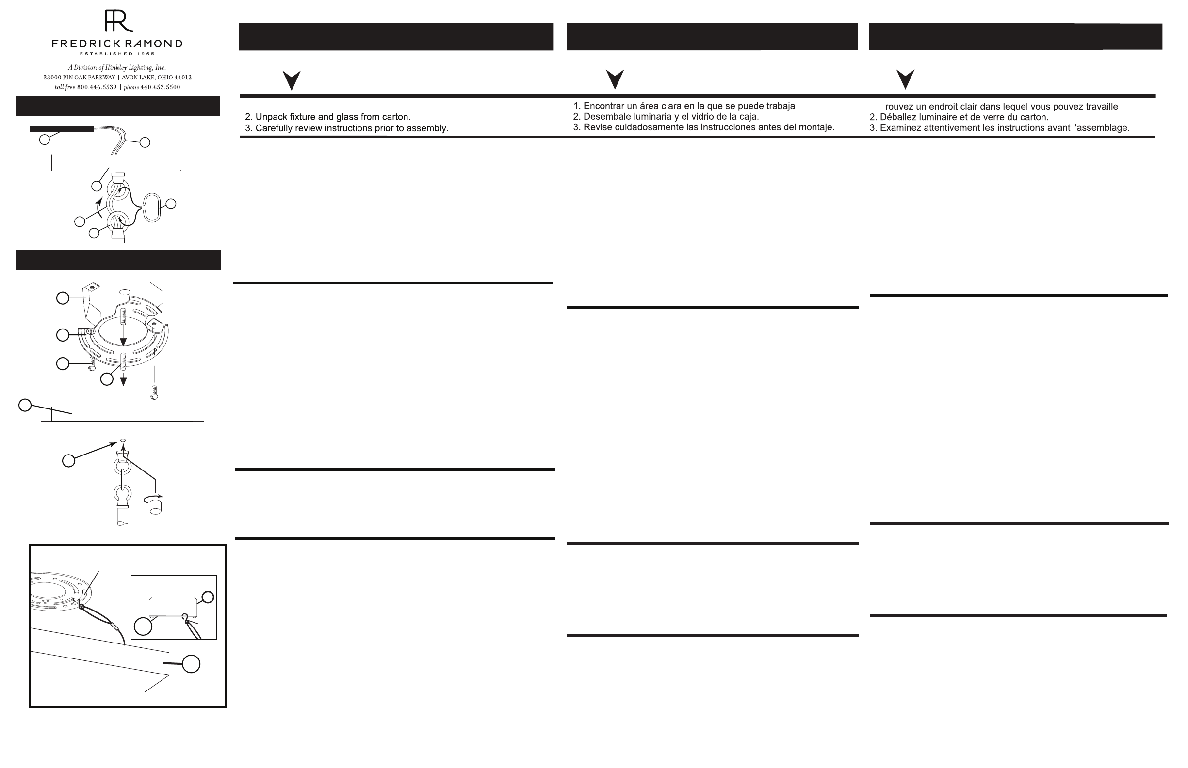
DRAWING 1 - CANOPY ASSEMBLY
S
C
W
L
W
CL
DRAWING 2 - MOUNTING
J
B
G
A
C
D
[Detail 1]
HOOK INSPECTION
CABLE TO MOUNTING STRAP.
B
C
J
HOOK
Item no. FR46407
English
ereh trats
.krow nac uoy hcihw ni aera raelc a dniF .1
1. If the stems of the fixture have not be attached to the main body.
Please do so at this time.
2. Attached the loop on the canopy (C) to the loop on the top of the
stems (L). This is accomplished by opening the chain link (CL) provided
and slipping it through the loops, and then closing it - see DRAWING 1.
3. Now slip the wires (W) from the stem through the center hole of the
loop in the canopy. NOTE: the fixture is supplied with a piece of black
sleeving (S). After the wires are slipped through the loops, slide the
black sleeving (S) over the black and red wires and through the loops
to cover them.
4. Fixture is ready to installation.
1. Install screws (A) into mounting plate (B) - see Drawing 1.
• Be sure the holes into which the screws are threaded match the
spacing of holes (D) in the canopy (C) - see Drawings 2.
2. Attach mounting plate (B) to junction box (J), using screws (G)
provided and then slip supply wires through large center hole.
3. Now take mounting plate (A) and attach it to the junction box (J) using
two 8-32 screws (G) NOT PROVIDED.
4. Now with assistance take the assembled fixture and lift it up to the
ceiling and using the hook on the end of inspection cable (I), attached to
the inside of canopy (C), hook it into the mounting plate (A). Now slowly
release the fixture until it is safely hanging from the inspection cable see DETAIL 1. NOTE: It is still recommend that an assistant be used to
support fixture during this process.
5. Make all necessary electrical connections following instruction sheet
(IS18) provided.
SAFETY WARNING: READ WIRING AND GROUNDING INSTRUCTIONS (I.S. 18) AND ANY ADDITIONAL DIRECTIONS. TURN POWER
SUPPLY OFF DURING INSTALLATION. IF NEW WIRING IS
REQUIRED, CONSULT A QUALIFIED ELECTRICIAN OR LOCAL
AUTHORITIES FOR CODE REQUIREMENTS.
5. To mount canopy (C) to ceiling, align holes (D) in the canopy with
screws (A) in mounting plate (B) and slip screws through holes. Hold
canopy against the ceiling and thread on barrel knobs (K) and tighten
them up against the canopy until it is secure against ceiling.
6. Wiring and installation is complete and power can be restored.
snoitcurtsnI gnitnuoM
Instrucciones de montaje
Número de Artículo. FR46407
1. Si los vástagos de la luminaria no se han unido al cuerpo
principal. Por favor, hazlo, en este momento.
2. Sujete los bucles en la cubierta (C) a los bucles en la parte
superior de los tallos (L). Esto se logra abriendo el eslabón de la
cadena (CL) provisto y deslizándolo a través de los bucles, y
luego cerrándolo - vea DIBUJO 1.
3. Ahora deslice los cables (W) desde el vástago a través del
orificio central del bucle en la cubierta. NOTA: el accesorio se
suministra con un pedazo de negro manga (S). Después de
deslizar los cables a través de los bucles, deslice los manga
negra (S) sobre los cables negro y rojo y por los bucles para
cubrirlos.
4. El accesorio está listo para la instalación.
1. Instale los tornillos (A) en la placa de montaje (B); vea el
Dibujo 1.
• Asegúrese de que los orificios en los que se roscan los
tornillos coincidan con la separación de los orificios (D)
en la campana (C); consulte los Dibujos 2.
2. Acople la placa de montaje (B) a la caja de conexiones (J),
usando los tornillos (G) provistos y luego deslice los cables de
suministro a través del orificio central grande.
3. Ahora tome la placa de montaje (A) y fíjela a la caja de
conexiones (J) usando dos tornillos 8-32 (G) NO
PROPORCIONADOS.
4. Ahora, con ayuda, tome el accesorio montado y levántelo
hasta el techo y, utilizando el gancho en el extremo del cable
de inspección (I), sujeto al interior de la cubierta (C), enganche
en la placa de montaje (A). Ahora, suelte lentamente el accesorio hasta que quede colgado del cable de inspección de
manera segura. Vea DETALLE 1. NOTA: Aún se recomienda
que se use un asistente para sostener el accesorio durante
este proceso.
ADVERTENCIA DE SEGURIDAD: LEA LAS INSTRUCCIONES
DE CABLEADO Y CONEXIÓN A TIERRA (I.S. 18) Y CUALQUIER
INSTRUCCIONES ADICIONALES. APAGUE LA FUENTE DE
ALIMENTACIÓN DURANTE LA INSTALACIÓN. SI SE REQUIERE NUEVO CABLEADO, CONSULTE A LAS AUTORIDADES
ELECTRICAS O LOCALES CUALIFICADAS PARA REQUISITOS
DE CÓDIGO.
5. Para montar la cubierta (C) en el techo, alinee los orificios (H)
en la cubierta con los tornillos (B) en la placa de montaje (1) y
deslice los tornillos a través de los agujeros. Sostenga la cubierta
contra el techo y enrosque las perillas del barril (4) y apriételas
contra la cubierta hasta que quede firme contra el techo.
6. El cableado y la instalación están completos y se puede
restaurar la energía.
íuqa razepme
Spanish
.r
Instrucciones de montaje
Numéro d'article. FR46407 French
ici zecnemmoc
T .1
1. Si les tiges du luminaire n’ont pas été attachées au corps
principal. S'il vous plaît faites-le, à ce moment.
2. Fixez les boucles de la canopée (C) aux boucles situées au
sommet des tiges (L). Ceci est accompli en ouvrant le maillon de
chaîne (CL) fourni et en le glissant dans les boucles, puis en le
refermant - voir SCHÉMA 1.
3. Maintenant, glissez les fils (W) de la tige à travers le trou central
de la boucle dans le couvert. NOTE: le luminaire est fourni avec un
morceau de noir gaine (S). Après avoir glissé les fils dans les
boucles, faites glisser le gaine noire (S) sur les fils noir et rouge et
à travers les boucles pour les couvrir.
4. Le luminaire est prêt à être installé.
1. Installez les vis (A) dans la plaque de montage (B) - voir dessin 1.
• Assurez-vous que les trous dans lesquels les vis sont
filetées correspondent à l'espacement des trous (D) dans le
dais (C) - voir Dessins 2.
2. Fixez la plaque de montage (B) à la boîte de jonction (J) à l'aide
des vis (G) fournies, puis faites glisser les câbles d'alimentation à
travers le grand trou central.
3. Maintenant, prenez la plaque de montage (A) et fixez-la à la boîte
de jonction (J) à l'aide de deux vis 8-32 (G) NON FOURNIES.
4. Maintenant, avec l'aide, prenez le montage assemblé et
soulevez-le au plafond. À l'aide du crochet situé à l'extrémité du
câble de contrôle (I), fixé à l'intérieur de l'auvent (C), fixez-le à la
plaque de montage (A). Maintenant, relâchez lentement l’appareil
jusqu’à ce qu’il soit suspendu en toute sécurité au câble d’inspection
- voir DÉTAIL 1. REMARQUE: Il est toujours recommandé de faire
appel à un assistant pour soutenir l’appareil pendant ce processus.
5. Effectuez tous les branchements électriques nécessaires en
suivant la fiche d'instructions (IS18) fournie.
AVERTISSEMENT DE SÉCURITÉ: LISEZ LES INSTRUCTIONS
DE CÂBLAGE ET DE MISE À LA TERRE (I.S. 18) ET TOUTES
LES INSTRUCTIONS SUPPLÉMENTAIRES. COUPEZ L'ALIMENTATION PENDANT L'INSTALLATION. SI UN NOUVEAU CABLAGE EST NÉCESSAIRE, CONSULTER UN ÉLECTRICIEN
QUALIFIÉ OU LES AUTORITÉS LOCALES POUR LES
EXIGENCES DU CODE.
5. Pour monter l'auvent (C) au plafond, alignez les trous (H) dans
l'auvent avec les vis (B) de la plaque de montage (1) et passez les
vis dans les trous. Tenez le capot contre le plafond et vissez les
boutons du canon (4) et serrez-les contre le capot jusqu'à ce qu'il
soit bien fixé au plafond.
6. Le câblage et l'installation sont terminés et le courant peut être
rétabli.
.r
H I N K L E Y L I G H T I N G 33000 Pin Oak Parkway Avon Lake, OH 44012 800.446.5539 / 440.653.5500 hinkleylighting.com
Page 3

Wiring Instructions for 0-10 volt LED dimmer
Instrucciones de cableado para atenuador LED de 0-10 voltios
Instructions de câblage pour gradateur LED 0-10 volts
DRAWING 1
DIMMER
start here
Your fixture is designed so it can use a standard incandescent
dimmer, Or a 0-10 volt LED dimmer. If a 0-10 volt LED dimmer is
used, it may be necessary to have additonal wiring installed from the
dimmer switch to the fixture. Consulting an electrician will be
necessary.
1. If using the optional 0-10 volt dimmer there will be four wires exiting
the junction box. (B) Black [+], (W) White [-], wirng are for the 120 /
277 voltage. The (G) Gray {-} and (P) Purple {+} are for the 0-10 volt
wires from the dimmer (D) - see Drawing 1.
2. The fixture has four wires of corrisponding colors. When make the
wire connections follow the chart below.
Black (B) from junction box (J) wired to Black (B) from fixture (F).
White (W) from junction box (J) wired to White (W) from fixture (F).
Gray/Pink(G) from junction box (J) wired to Gray/Pink (G) from fixture
(F).
Purple (P) from junction box (J) wired to Purple (P) from fixture (F)
INCANDESCENT DIMMER USAGE:
If using an incandescent dimmer follow manufactures instructions.
NOTE: MAKE SURE TO CAP OFF THE GRAY AND PURPLE WIRE
FROM THE FIXTURE INSIDE THE CANOPY. IF THE ARE NOT
CAPPED THEY CAN SHORT OUT AND CAUSE THE FIXTURE TO
FAIL.
empezar aquí
Su luminaria está diseñada para que pueda usar un atenuador
incandescente estándar o un atenuador LED de 0-10 voltios. Si se utiliza
un atenuador LED de 0-10 voltios, puede ser necesario instalar cableado
adicional desde el interruptor atenuador hasta la luminaria. Consultar a un
electricista será
1. Si usa el atenuador opcional de 0-10 voltios, habrá cuatro cables
saliendo de la caja de conexiones. (B) Negro [+], (W) Blanco [-], los
cables son para el voltaje 120/277. El (G) Gris {-} y (P) Morado {+} son
para los cables de 0-10 voltios del atenuador (D); consulte el Dibujo 1.
2. La luminaria tiene cuatro hilos de colores correspondientes. Al realizar
las conexiones de cables, siga la tabla a continuación.
Negro (B) de la caja de empalmes (J) cableado a Negro (B) del
accesorio (F).
Blanco (W) de la caja de empalmes (J) cableado a Blanco (W) del
accesorio (F).
Gris/Rosa (G) desde la caja de empalmes (J) cableado a Gris/Rosa (G)
desde la luminaria (F).
Púrpura (P) desde la caja de empalmes (J) cableado a Púrpura (P)
desde el accesorio (F)
USO INCANDESCENTE DEL DIMMER:
Si usa un atenuador incadescente, siga las instrucciones del fabricante.
NOTA: ASEGÚRESE DE TAPAR EL CABLE GRIS Y PÚRPURA DE LA
LUMINARIA DENTRO DEL DOSEL. SI NO ESTÁN TAPADOS,
CAUSAN UN CORTOCIRCUITO Y LA LUMINARIA NO FUNCIONA.
commencez ici
Votre luminaire est conçu pour pouvoir utiliser un variateur à incandescence standard ou un variateur LED 0-10 volts. Si un gradateur LED
0-10 volts est utilisé, il peut être nécessaire d'avoir un câblage supplémentaire installé entre le variateur et le luminaire. Consulter un
électricien sera
1. Si vous utilisez le gradateur optionnel 0-10 volts, quatre fils sortent de
la boîte de jonction. (B) Noir [+], (W) Blanc [-], le câblage est pour la
tension 120/277. Les (G) Gray {-} et (P) Purple {+} sont pour les fils 0-10
volts du gradateur (D) - voir Schéma 1.
2. Le luminaire a quatre fils de couleurs correspondantes. Lorsque vous
effectuez les connexions des fils, suivez le tableau ci-dessous.
Noir (B) de la boîte de jonction (J) câblé au noir (B) du luminaire (F).
Blanc (W) de la boîte de jonction (J) câblé au blanc (W) du luminaire (F).
Gris/rose (G) de la boîte de jonction (J) câblé au gris/rose (G) du
luminaire (F).
Violet (P) de la boîte de jonction (J) câblé à Violet (P) du luminaire (F)
UTILISATION INCANDESCENTE DU DIMMER:
Si vous utilisez un variateur à incandescence, suivez les instructions du
fabricant.
REMARQUE: ASSUREZ-VOUS DE COUVERCLE LE FIL GRIS ET
VIOLET DU LUMINAIRE À L'INTÉRIEUR DE L'AUVENT. S'ILS NE
SONT PAS PLAFONNÉS, ILS PROVOQUENT UN COURT-CIRCUIT ET
LE LUMINAIRE NE FONCTIONNE PAS.
J
SUPPLY WIRES
FROM
JUNCTION BOX
B
W
B
W
D
P
P
driver
blue/black
SWITCH
WIRES FROM
DIMMER
G
G
red
wires to LEDS
 Loading...