

Frederiksen 4410.30 User Manual
Note:
The purpose of this apparatus is to
measure very small electrical
currents and charges. It is there fore very sensitive to disturbances that you
normally would neglect completely. Please
read the section “Application hints”
DESCRIPTION OF THE APPARATUS
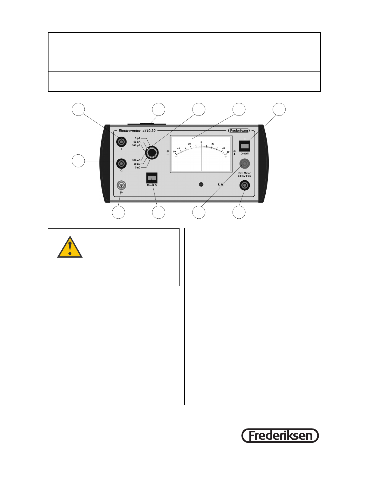
The electrometer has on its left side input connectors for current (1) and charge (2). The reading is
shown on a zero centered analogue instrument (5).
The scale goes from “-50” to “50” and is read in
connection with the setting of the switch (4). If for instance the switch is set to 500 nC, the meter will
read from -500 nC to 500 nC.
During charge measurements the apparatus can be
zeroed with the switch (8).
An output is provided between the sockets (9) and
(10) for data logging or a demonstration meter. The
voltage varies between -500 mV and 500 mV,
corres ponding to meter readings between “-50” and
“50”.
The yellow/green socket (7) to the left as well as the
black socket (10) to the right are connected to chassis ground.
The apparatus is driven by a 9 V battery, placed in
the holder (3).
Current measurements
The input I is used with the switch settings 5 pA,
50 pA and 500 pA for measuring small currents.
The current goes through a 1 GΩ resistor.
This results in a voltage drop in the three measuring
ranges of respectively 5 mV, 50 mV and 500 mV.
The current input is not protected against an overvoltage larger than 1 kV (corresponding to a current
of 1 µA or 1,000,000 pA).
Charge measurements
The input Q is used with the switch settings 5 nC,
50 nC and 500 nC for measuring charge.
The charge measurement can be zeroed by pressing
Reset Q.
Charge is transferred to an internal 1 µF capacitor.
This results in a voltage in the three measuring
ranges of respectively 5 mV, 50 mV and 500 mV. In
connection with typical electrostatic experiments
Manual for electrometer no. 4410.30
09.12.08 Ae 4410.30
A/S Søren Frederiksen, Ølgod Tel. +45 7524 4966 info@frederiksen.eu
Viaduktvej 35 · DK-6870 Ølgod Fax +45 7524 6282 www.frederiksen.eu
®
1
2
3 4 5 6
7 8 9
10

(with voltages in the kilovolts range), this voltage can
be considered to be 0 V.
In other words, when measuring for instance the
charge of a metal sphere, the measuring process
can be viewed as a discharge of the sphere while
concurrently keeping track of the amount of charge
that leaves the sphere.
The charge input withstands a lasting voltage up to
70 V (corresponding to a charge of 70 µC or
70,000 nC).
During electrostatic experiments where charge is
transferred to the input by a ball or the like, there is
no risk of damaging the apparatus – only if the input
is connected directly to a high voltage supply, bad
things will happen.
APPLICATION HINTS
Grounding
In all experiment with static electricity or tiny currents it is an advantage to have a well-defined zero
for all voltages. Normally you chose “earth” as this
zero point.
A correctly installed, grounded mains socket pro vides this zero potential. When you are using for instance our 6kV supply 3660.50 or the 500V supply
3655.60/65 with the appropriate power cord, the
ground connection is available as the yellow/green
socket on the back. This should be connected to the
electrometer chassis – either the yellow/green
socket to the left or the black socket to the right.
If you work on a table with a metal frame, you may
with advantage ground connect this also (eventually
by means of an alligator clip).
If you also ground a 4410.02 insulated rod or a terminal like 4350.10 you have an un-insulated ground
to discharge diverse metal balls as well as the experimenter.
Removing static charges
If you want to experiment with electric charges by
means of for instance a 4415.00 metal plated ball on
rod, the experiment may be disturbed by small charges on the rod.
If a radioactive alpha source with a Perspex handle
is used with the 4410.35 ionization chamber you
may again observe that the apparatus reacts to
charges on the handle.
Likewise charges may be created on the plastic insulation of the sockets of the apparatus when a cord
is pulled out. Such charges may seep in to the I input and show itself as a current that only very slowly
falls towards zero – and that may be strong enough
to throw the instrument off scale.
In the last case the problem is usually remedied by
moistening a cotton swab with 96 % ethanol and inserting it into the socket. After removing it again and
the liquid has evaporated, the dial should go to rest
at zero.
To remove charges on insulated rods, you may also
use 96 % ethanol. You should be aware that there is
a risk that Perspex may get frosted or even crackle
by contact with ethanol. It should be mentioned that
our 4415.00 metal plated ball on rod uses a Perspex
rod – but we have in fact never observed problems
with the use of ethanol in connection with our work
with the apparatus.
EXPERIMENTS
The accessories mentioned are not part of 4410.13
but may be ordered separately.
The ionization chamber
The ionization chamber (4410.35) consists of a center electrode and a surrounding grid electrode. The
center electrode is put into the I input such that the
connector to the grid electrode is positioned to the
left of the cabinet. Connect the grid electrode to a
normal low voltage supply (for instance 3630.00)
which has its other pole connected to the electrometer’s ground (black socket to the right – or eventually yellow/green socket to the right). The measuring range should be 5 or eventually 50 nA. Check
that the socked has not been charged. While turning
up the voltage to something like 10 V, you will observe a momentary current as the grid is charged –
but this should vanish fast, making the current approximately zero.
Prepare an alpha source (like our 37 kBq Am-241
source) so the handle is not charged, and move it
close to the ionization chamber. When it gets close
enough, you will observe a current running between
the electrodes – the air has been partially ionized.
Likewise, you can place a burning match near the ionization chamber and gently blow the flame in the
direction of the chamber. The free ions from the
flame are enough to carry a measurable current.
A small signal diode as a photo detector
A solar cell is in fact just a diode with a special appearance. An ordinary small signal diode in a glass
housing (as for instance 1N4148) has in fact the
same photoelectrical properties – the light sensitive
area is just substantially smaller, giving rise to
photocurrents in the picoampere range.
Set the range switch at 500 pA and connect the
diode between the I input and zero ( ) with a
couple of leads and alligator clips.
®
 Loading...