

Page 1

PV series Solar Pumping Inverter
IMPORTANT NOTES
◆To illustrate the details of the products,pictures in this manual based on products with outer
casing or safety cover being removed. When using this product, please be sure to well install
outer casing or covering by the rules, and operating in accordance with the manual contents.
◆The illustrations in this manual are for illustration only and may vary with different products
you have ordered.
◆The company is committed to continuous improvement of products, product features will
continue to upgrade, the information provided is subject to change without notice.
◆If there is any questions when using, please contact our regional agents or our customer
service center:(+86-0755-33067999)
◆For other products, please visit our website. http://www.frecon.com.cn
Preface
PV200 special inverters are developed for power supply of water pumps, based on the core
control arithmetic of FR200 vector control inverters, combined with the control requirements of PV
water pump application. The function of maximum power tracking, dormant at weak light, wake up at
strong light, high water level dormant, under-load pre-warning and other control protection functions
can ensure normal operation of water pumps according to the customers’ requirements to switch to the
grid power supply.
Please refer to this manual to commission the inverter, product maintenance refer to FR200 user
manual.
- 1 -
Page 2

PV series Solar Pumping Inverter
- 2 -
Page 3
PV series Solar Pumping Inverter
Contents
Preface .......................................................................................................................................................... - 1 -
Contents ....................................................................................................................................................... - 3 -
Chapter One Product Overview ............................................................................................................... - 4 -
1.1 Name Plate ........................................................................................................................................ - 4 -
1.2 Product Specifications ...................................................................................................................... - 5 -
1.3 Dimension Drawing .......................................................................................................................... - 8 -
Chapter Two Commissioning Guide .................................................................................................... - 11 -
2.1 PV Panel Power Supply Commissioning ..................................................................................... - 11 -
2.2 Grid or Generator power supply wirings ...................................................................................... - 13 -
2.3 Wiring diagram between VFD and single phase motor .............................................................. - 15 -
2.4 Product Terminal Configuration .................................................................................................... - 18 -
Chapter Three Function Parameters .................................................................................................... - 22 -
3.1 The Basic Function Parameters .................................................................................................... - 22 -
3.2 H00 Group: Detailed Explanation of Function Code .................................................................. - 39 -
Chapter Four Troubleshooting and Countermeasures .................................................................... - 45 -
- 3 -
Page 4
PV series Solar Pumping Inverter
PV200-4T-2.2B
Products series Number
PV: Solar Pump Inverter
Input voltage level
4T: Three phase 380V
2T: Three phase 220V
2S: Single phase 220V
Braking Unit (Built-in )
Output power: 2.2kW
Chapter One Product Overview
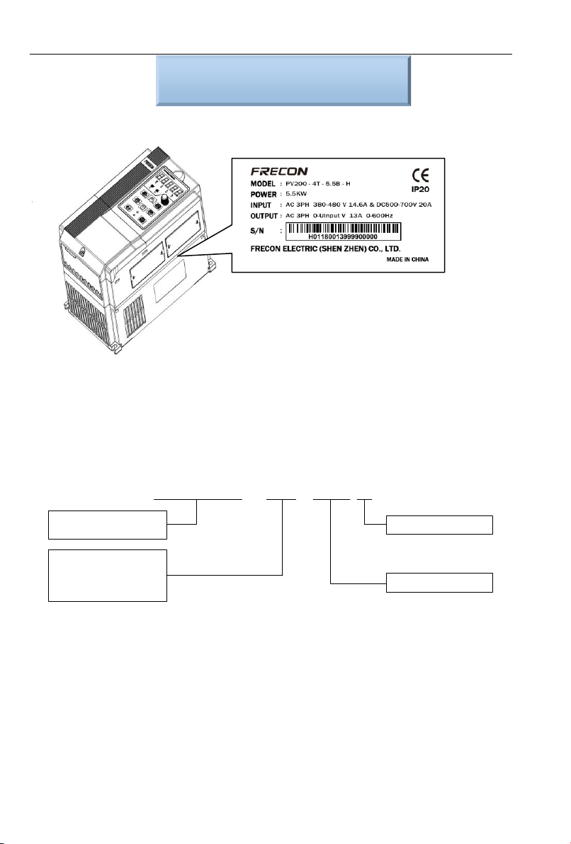
1.1 Name Plate
Figure 1-1 Name Plate
Model Instruction
Model numbers on name plate consist of numbers, symbols, and letters, to express its respective
series, suitable power type, power level and other information.
Figure 1-2 Product Model Naming Rules
- 4 -
Page 5
PV series Solar Pumping Inverter
Model No.
Recommended
Solar Array
Power kWP
Maximum
Input DC
Current A
Output
Current A
Adaptive
Motor kW
Size of
the Case
PV100-2S-0.2B
0.35
2.5
1.6
0.18, 0.2, 0.25
P1-1
PV100-2S-0.4B
0.6
4.5
2.5
0.37, 0.4
PV100-2S-0.7B
1.1
7.5
4.2
0.75
PV100-2S-1.5B
2.25
10
7.5
1.5
P1-2
PV100-2S-2.2B
3.3
18
9.5
2.2
PV100-2T-0.2B
0.35
2.5
1.6
0.18, 0.2, 0.25
P1-1
PV100-2T-0.4B
0.6
4.5
2.5
0.37, 0.4
PV100-2T-0.7B
1.1
7.5
4.2
0.75
PV100-2T-1.5B
2.25
10
7.5
1.5
P1-2
PV100-2T-2.2B
3.3
18
9.5
2.2
PV200-2T-0.7B
3.5
5.3
5
0.18, 0.2, 0.25
P2-1
PV200-2T-1.5B
5.5
8.5
8
0.37, 0.4
P2-2
PV200-2T-2.2B
7.5
11.6
11
2.2
PV200-2T-4.0B
11.7
18
17
4.0
PV200-2T-5.5B
17.3
26.5
25
5.5
P2-3
PV200-2T-7.5B
22
33.5
32
7.5
PV200-2T-011B
31
47.5
45
11
P2-4
PV200-2T-015B
41.5
63
60
15
PV200-2T-018
52
79
75
18
P2-5
PV200-2T-022
63
96
91
22
PV200-2T-030
77.5
118
112
30
P2-6
PV200-2T-037
104
158
150
37
PV200-2T-045
122
185
176
45
P2-7
PV200-2T-055
145
221
210
55
PV200-2T-075
173
263
250
75
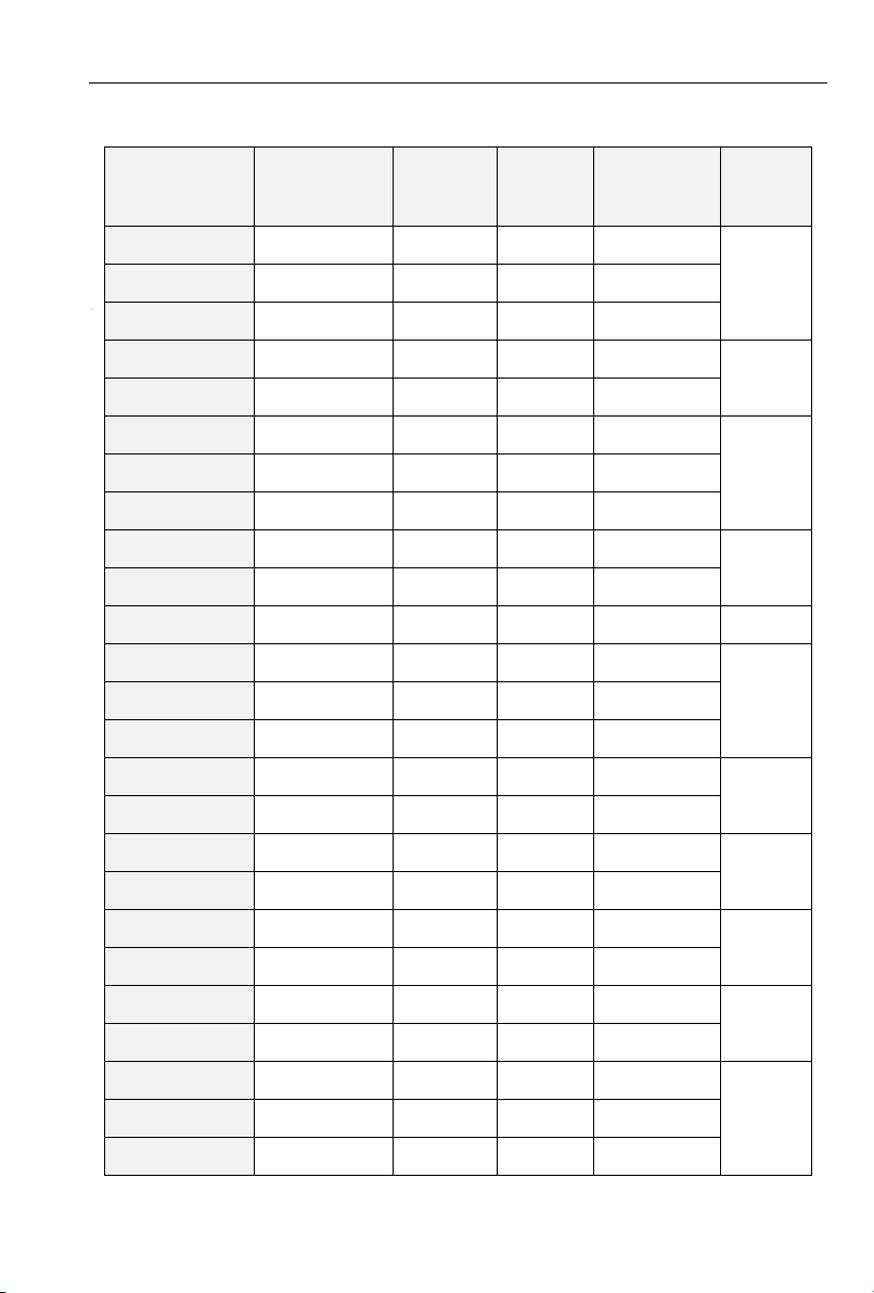
1.2 Product Specifications
1.2.1 Electric specification of AC220V and DC310V Input product
Table 1-1 Electric specification of AC220V and DC310V Input product
- 5 -
Page 6
PV series Solar Pumping Inverter
Input specification
PV Input
Maximum Input DC
Voltage
400VDC
Recommended Voc
Range
320~370VDC
Recommended MPPT
Voltage Range
250~350VDC
Starting Voltage
Range
120~400VDC
Grid or backup generator input
Input voltage
Single phase 220V(-15%~30%)
Output specification
Rated output voltage
3PH 220V
Output frequency
0~600.00Hz(default: 0~50.00Hz)
Protection
Built-in Protection
Lighting Protection, over-current, overvoltage, output phase-lose,
under-load, under-voltage, short circuit, overheating, water pump run
dry etc.
Model No.
Power
Capacity
kVA
Input
Current A
Output
Current A
Adaptive
Motor kW
Size of the
case
PV100-4T-0.7B
1.5
3.4
2.5
0.75
P1-2
PV100-4T-1.5B
3
5.0
4.2
1.5
PV100-4T-2.2B
4
5.8
5.5
2.2
PV100-4T-4.0B
6
11
9.5
3.7、4
PV200-4T-0.7B
1.5
3.4
2.5
0.75
P2-1
PV200-4T-1.5B
3
5.0
4.2
1.5
PV200-4T-2.2B
4
5.8
5.5
2.2
PV200-4T-4.0B
6
11
9.5
3.7、4
P2-2
PV200-4T-5.5B
8.9
14.6
13
5.5
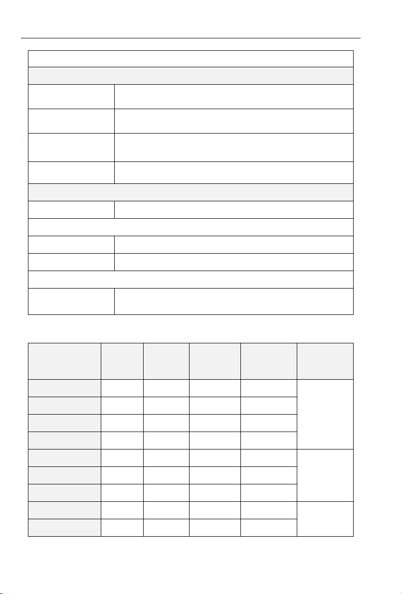
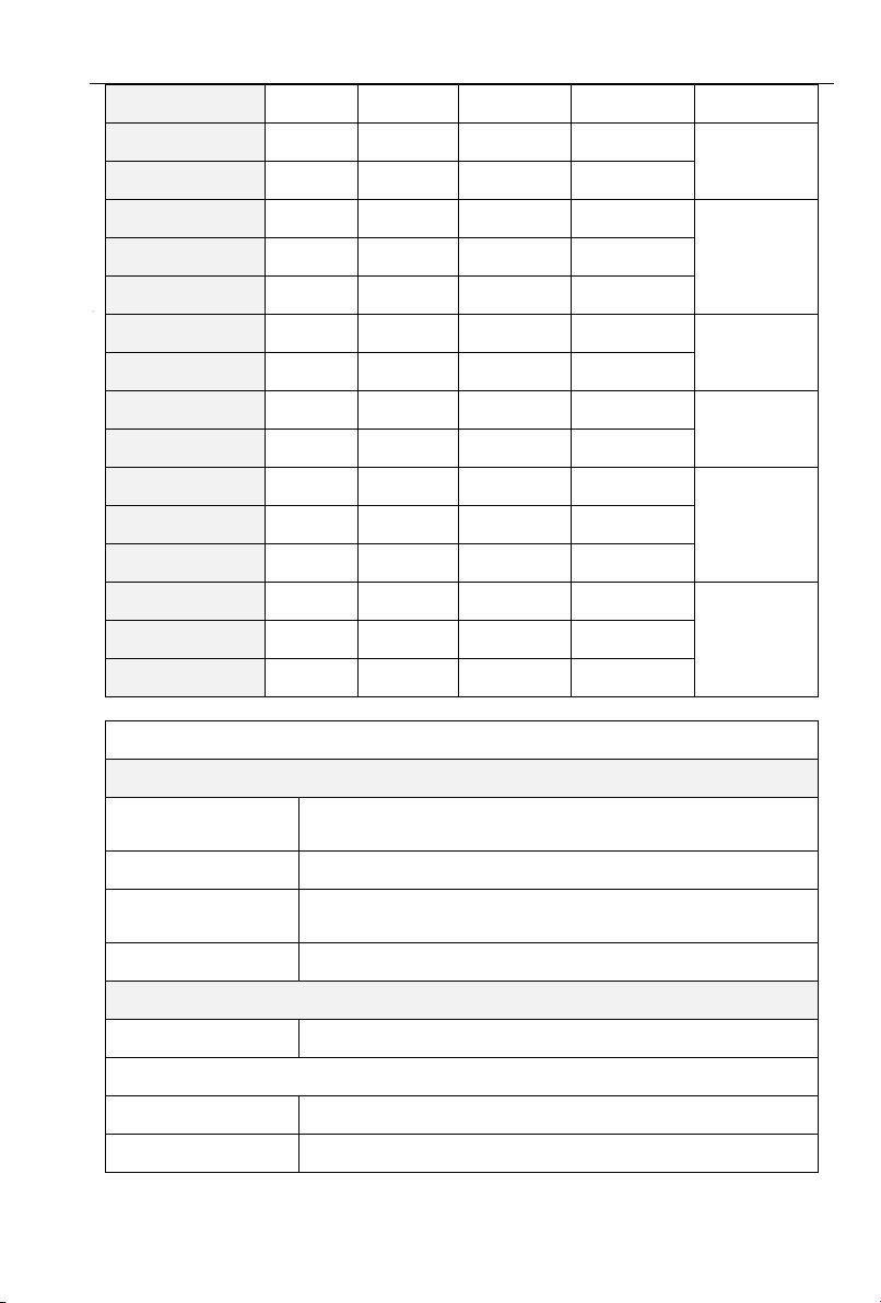
1.2.2 Electric specification of AC 380V&DC 540V Input product
Table 1-2 Electric specification of AC 380V&DC 540V Input product
- 6 -
Page 7
PV series Solar Pumping Inverter
PV200-4T-7.5B
11
20.5
17
7.5
PV200-4T-011B
17
26
25
11
P2-3
PV200-4T-015B
21
35
32
15
PV200-4T-018B
24
38.5
37
18.5
P2-4
PV200-4T-022B
30
46.5
45
22
PV200-4T-030B
40
62
60
30
PV200-4T-037
57
76
75
37
P2-5
PV200-4T-045
69
92
91
45
PV200-4T-055
85
113
112
55
P2-6
PV200-4T-075
114
157
150
75
PV200-4T-090
134
160
176
90
P2-7
PV200-4T-110
160
190
210
110
PV200-4T-132
192
232
253
132
PV200-4T-160
231
282
304
160
P2-8
PV200-4T-185
240
326
350
185
PV200-4T-200
250
352
377
200
Input specification
PV Input
Maximum Input DC
Voltage
800VDC
Recommended Voc
Range
500~700VDC
Recommended MPPT
Voltage Range
450~600VDC
Starting Voltage Range
250~800VDC
Grid or backup generator input
Input Voltage
Three phase 380V(-15%~30%)
Output specification
Rated output voltage
3PH 380V
Output frequency
0~600.00Hz(Default 0~50.00Hz)
- 7 -
Page 8
PV series Solar Pumping Inverter
Protection
Built-in Protection
Lighting Protection, over-current, overvoltage, output phase-lose,
under-load, under-voltage, short circuit, overheating, water pump run
dry etc.
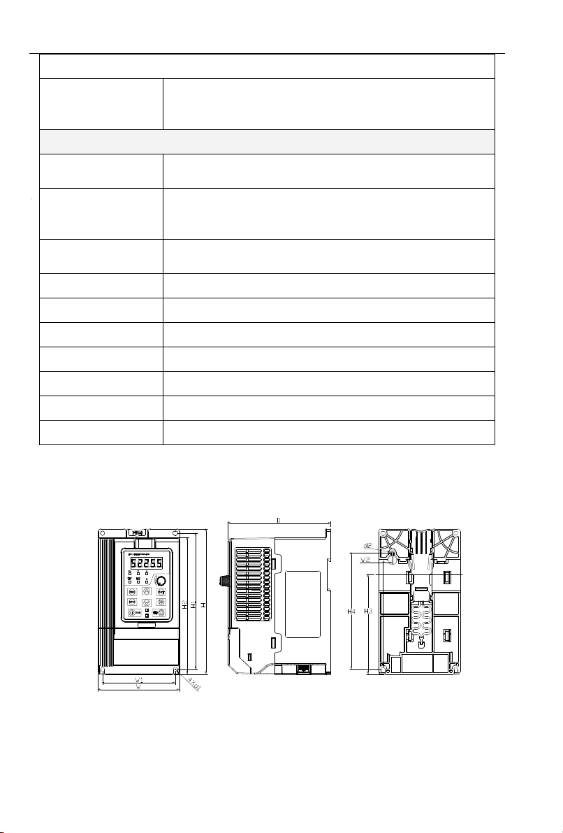
General Parameters
Application Site
No direct sunshine, no dust、corrosive gas、combustible gas、oil mist、
steam、dripping or salinity etc.
Altitude
0~2000 m
Derated use above 1000m,per 100m, the rated output current
decrease 1%.
Environment
Temperature
-10℃~40℃ (Environment Temperature be 40℃~50℃, please
keep derated use.)
Humidity
5~95%,non-condensation
Vibration
less than 5.9 m/s2(0.6g)
Storage Temperature
-20℃~+70℃
Efficiency
Rated Power Run≥93%
Installation
Wall or rail mounting
Protection Grade
IP20
Cooling
Forced Air Cooling
1.3 Dimension Drawing
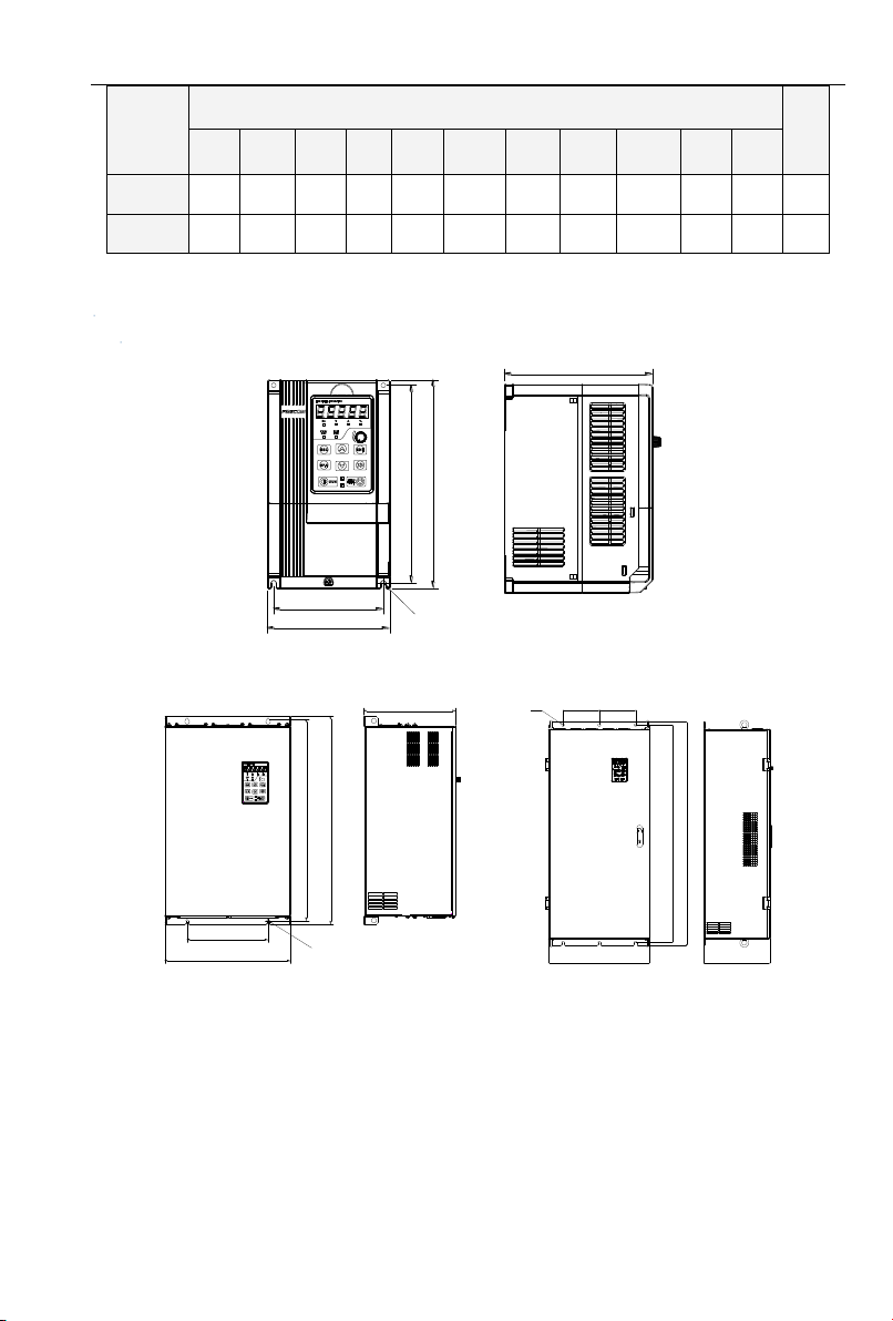
1.3.1 PV100
Table 1-3 PV100 Size Table
- 8 -
Page 9
PV series Solar Pumping Inverter
Model No.
Dimensions and installation size(mm)
kG
W H D
W1
W2
H1
H2
H3
H4
d1
d2
P1-1
95
162
120
85
11
151.5
152
110.8
130
4.5
4.5
1.1
P1-2
110
173
135
100
11
163
163
121.8
140.5
4.5 5 1.5
W1
H1
H
W
D
4Xd
W1
W
H1
H
D
4xd
H
W
D
H1
d W1 W1
1.3.2 PV200
a: 0.75~15kW Dimensions and wall mounting dimensions
Figure 1-3 0.75~15kW Wall Installation Diagram
b: 18.5~200kW Dimensions and installation dimensions
Figure 1-4 18.5~30kW Wall Mounting Diagram Figure 1-5 37~200kw Wall Mounting Diagram
- 9 -
Page 10
PV series Solar Pumping Inverter
Model No.
Dimensions and installation size(mm)
Weight
(Kg)
W
W1 H H1
D
Installation
Aperture
P2-1
117
106.6
187
176.6
160
4.5
2.2
P2-2
146
131
249
236
177
5.5
3.2
P2-3
198
183
300
287
185
5.5
5.4
P2-4
255
176
459
443
220 7 15.5
P2-5
270
130
590
572
260 7 27.5
P2-6
357
230
590
572
260 7 37
P2-7
430
320
829.5
802
293
12
77.7
P2-8
500
180
1107
1078
328
14
138.5
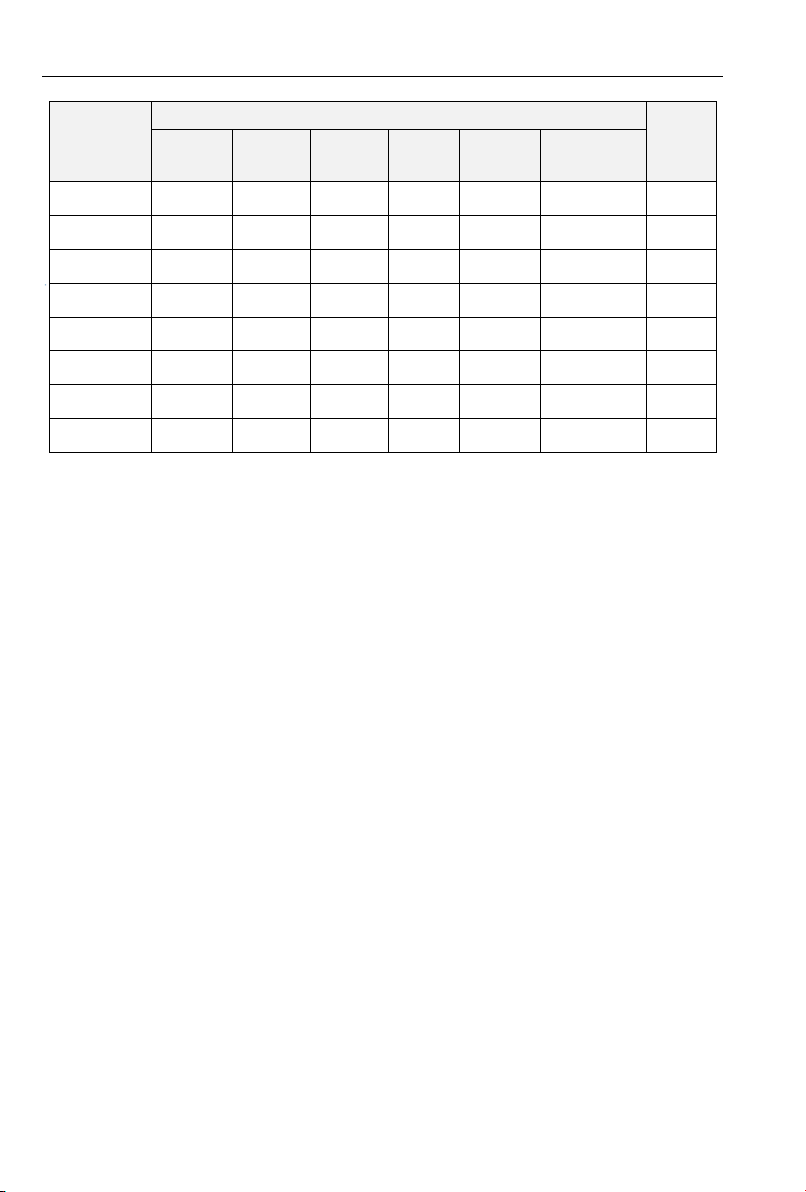
Table 1-4 Wall Mounting Size Table
- 10 -
Page 11
PV series Solar Pumping Inverter
PV panels
Q1
R/L1
S/L2
T/L3
+24V
DI1
DI2
DI3
DI4
DI5
DI6
+10V
AI1
AI2
GND
PE
U/T1
V/T2
W/T3
485+
485-
GND
R1A
R1B
R1C
M
(-) (+) PB
PV200
Y2/HO
PLC
DI7/HI
COM
AI3
AO1
GND
+24V
Y1
AO2
GND
R2A
R2B
R2C
+
-
Note: The common
terminal of PV100 is
GND.
Tank
The water
level sensor
RUN/STOP
Short film
Operation panel
Chapter Two Commissioning Guide
2.1 PV Panel Power Supply Commissioning
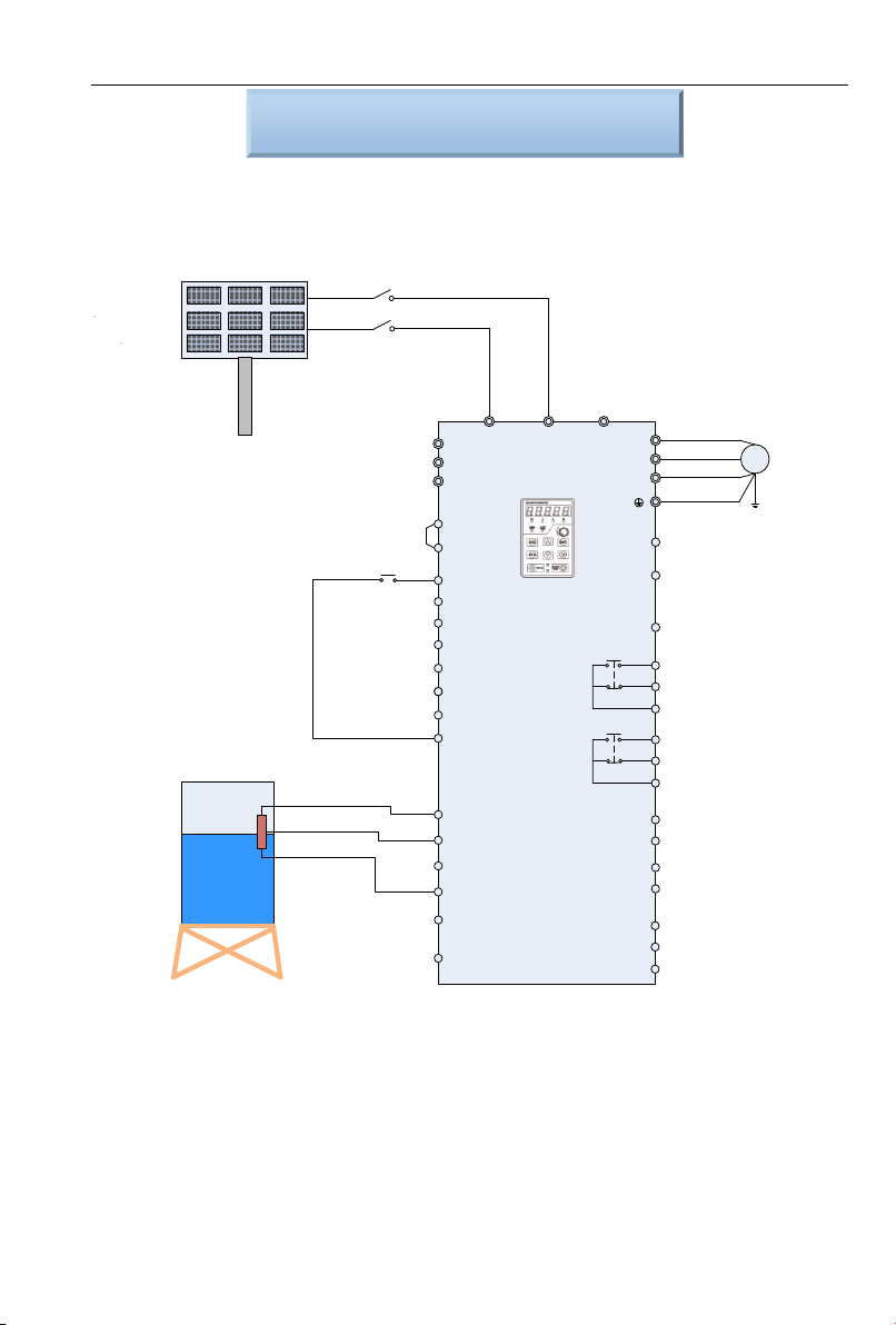
1. Wiring drawings of below inverters shown as Figure 2-1: PV100 series, PV200 series 3 phase 220V
inverters with power lower than 15kw and 3 phase 380V inverters with power lower than 30kw.
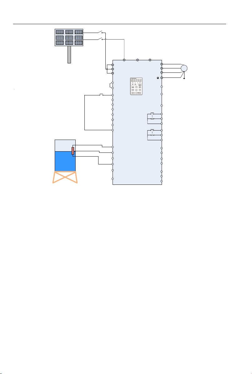
Wire drawings of below inverters shown as Figure 2-2: PV200 series 3 phase 220V inverters with
power higher than 18kw and 3phase 380V inverters with power higher than 37kw.
Figure 2-1 PV Cell Power Supply Wiring Diagram 1
- 11 -
Page 12
PV series Solar Pumping Inverter
Tank
The water
level sensor
PV panels
Q1
R/L1
S/L2
T/L3
+24V
DI1
DI2
DI3
DI4
DI5
DI6
+10V
AI1
AI2
GND
PE
U/T1
V/T2
W/T3
485+
485-
GND
R1A
R1B
R1C
RUN/STOP
M
(-) (+) PB
PV200
Operation panel
Y2/HO
PLC
DI7/HI
COM
AI3
AO1
GND
+24V
Y1
AO2
GND
R2A
R2B
R2C
+
-
Short film
Note: if it is connected to the power or
generator, the terminal short films
between R/S/T must be removed, or
will cause the fires, and even
casualties risk
Short film
Figure 2-2 PV Cell Power Supply Wiring Diagram 2
1. Please wirings as Figure 2-1 or Figure 2-2 according to different inverter powers, check and confirm
the wirings to be correct, and then close Q1.
2. Setting the Motor Parameters
Setting the parameter of name plate on motor F08.01~F08.05。
3. Testing the water yield of pump
Press the operation key “RUN”, under normal circumstance of light strength, if the operation
frequency low or water yield less, which means the motor wiring may be reversed, please exchange
two wirings of motor.
4. System Effluent Speed PI Regulating
If the user has a high requirements for the effluent speed, PI parameters can be regulated
appropriately(H00.09~H00.10), the larger PI parameter, the stronger affection, the faster effluent,
but the larger fluctuation of motor frequency; Otherwise, the slower water effluent, the more steady
frequency of motor operation.
5. MPPT Tracing Speed Commissioning
H00.04 and H00.05 are respectively the lowest voltage and highest voltage under the MPPT mode,
the smaller the range between them two, the faster tracing the maximum power, but the premise if
that the bus voltage during normal operation must fall within this range, or the maximum power point
may not be tracked. Generally speaking, the factory default value is OK.
- 12 -
Page 13
PV series Solar Pumping Inverter
Q1
R/L1
S/L2
T/L3
+24V
DI1
DI2
DI3
DI4
DI5
DI6
+10V
AI1
AI2
GND
PE
U/T1
V/T2
W/T3
485+
485-
GND
R1A
R1B
R1C
Q2
M
(-) (+) PB
PV200
Y2/HO
PLC
DI7/HI
COM
AI3
AO1
GND
+24V
Y1
AO2
GND
R2A
R2B
R2C
PV panels
Note: The common
terminal of PV100 is
GND.
Grid or
generator set
PV Voltage
Given selection
Operation panel
Tank
The water
level sensor
RUN/STOP
6. Setting of fault point and fault delay reset time
If clients need to use the pre-warning of weak light, water-logged, under-load, failure monitoring
point, delay time and reset time, water-logged/controlled function can be set as H00.15~H00.19 on
demand; under-load function set as H00.20~H00.22; weak light function set as H00.13~H00.14.
Users also can adopt the default value.
7. Parameter setting after the system operation normally
When the water yield is normal, and system run steadily, the commissioning will be finished. And
then setting F02.00=1, change to terminal operation mode, setting failure auto reset times
F11.27=5.
2.2 Grid or Generator power supply wirings
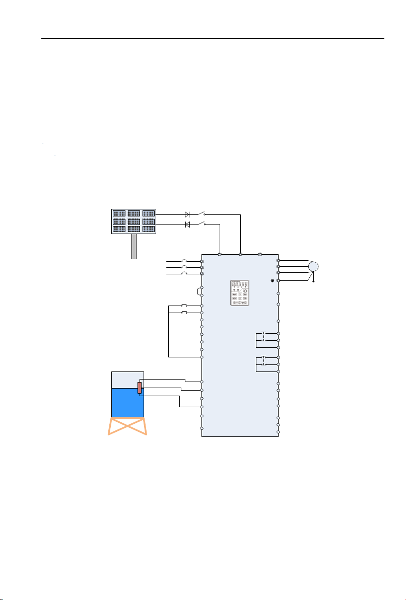
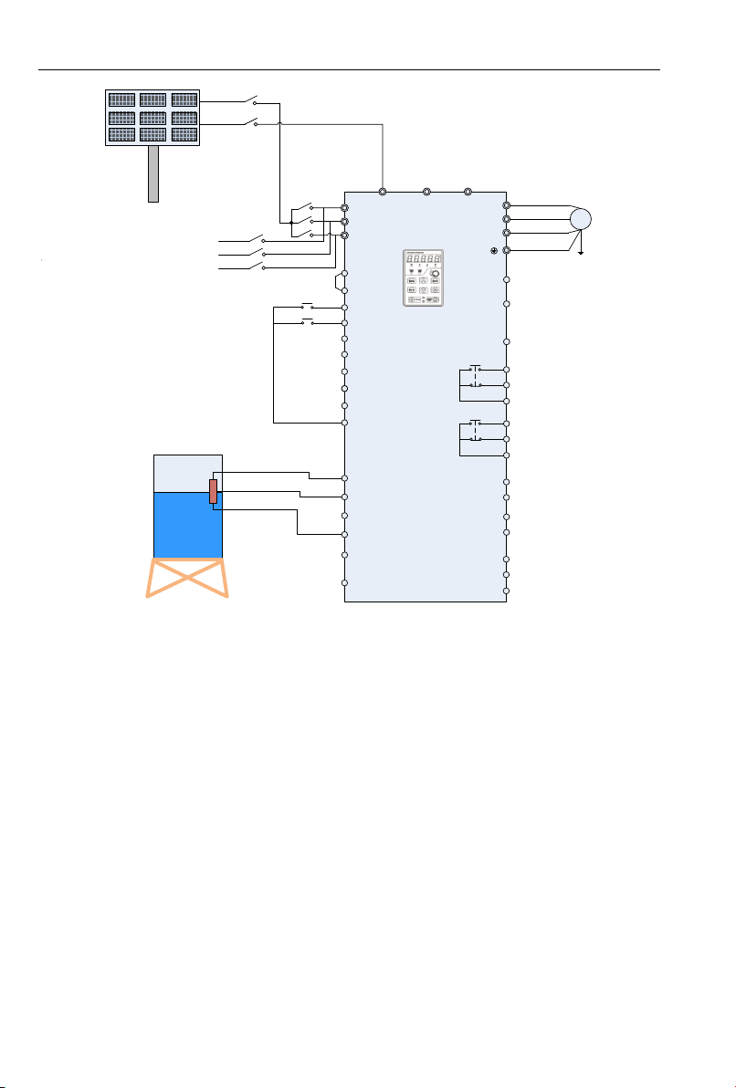
Wiring drawings of below inverters shown as Figure 2-3: PV100 series, PV200 series 3 phase
220V inverters with power lower than 15kw and 3 phase 380V inverters with power lower than 30kw.
power higher than 18kw and 3phase 380V inverters with power higher than 37kw.
Wire drawings of below inverters shown as Figure 2-4: PV200 series 3 phase 220V inverters with
Figure 2-3 Grid or Generator Power Supply Wiring Diagram 1
- 13 -
Page 14
PV series Solar Pumping Inverter
PV panels
Q1
R/L1
S/L2
T/L3
+24V
DI1
DI2
DI3
DI4
DI5
DI6
+10V
AI1
AI2
GND
PE
U/T1
V/T2
W/T3
485+
485-
GND
R1A
R1B
R1C
M
(-) (+) PB
PV200
Y2/HO
PLC
DI7/HI
COM
AI3
AO1
GND
+24V
Y1
AO2
GND
R2A
R2B
R2C
KM1
KM2
+
-
Note:KM1 and KM2
is a pair of
interlocking
contactors
Grid or
generator set
PV Voltage
Given selection
Operation panel
Tank
The water
level sensor
RUN/STOP
Short film
Figure 2-4 Grid or Generator Power Supply Wiring Diagram 2
1. Wirings as Figure 2-3 system wiring drawings according to inverters power, check and confirm
the connections to be correct.
2. Disconnect the switch Q1, and then close Q2, switch to grid or diesel engine power;
disconnect Q2, and then close Q1, switch to PV power supply; Figure 2-4 show inter-locking
connection between connector KM1 and KM2, KM1 close is PV power supply, KM2 close is
grid or generator power supply.
3. When grid or generator power supply, setting H00.01=0, power supplied by grid.
4. For water pump’s frequency, please refer to F01 group code, H00.02~H00.12 function code
does not work.
5. When change to PV power supply, setting F04.1=38 and close the terminal DI2 (or setting
H00.01=1).
Note:
When the bus input terminal does not install the diode protection, PV panel switch Q1 will be
prohibited to close together with grid power input switch Q2, or the panel will be damaged.
- 14 -
Page 15
PV series Solar Pumping Inverter
Main
winding
Secondary
winding
Starting
capacitor
U1
U2
Z1
Z2
M
220VAC
Main
winding
Secondary
winding
Starting
capacitor
U1
U2
Z1
Z2
M
220VAC
Centrifugal
switch
2.3 Wiring diagram between VFD and single phase motor
2.3.1 Single phase motor introduction
Single phase motor generally means asynchronous single phase motor powered by single phase
AC 220V, there’re two phase winding in motor stator and motor rotor is common squirrel cage. The
distribution of two phase winding and different power supply will lead to different starting
characteristics and operating characteristics
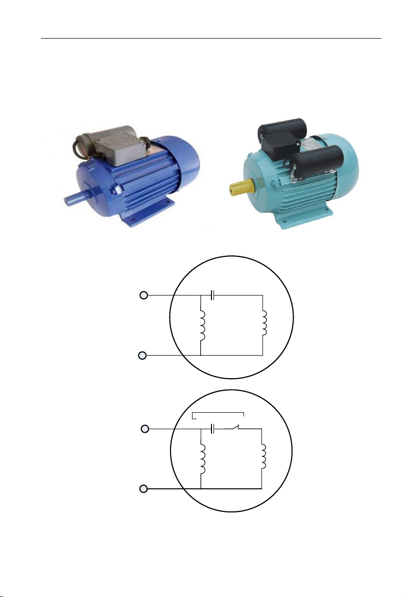
Usually single phase motor is with single capacitor or double capacitor, photos of motor are as
below:
Single phase motor is consisted of main winding, secondary winding, capacitor and centrifugal
Figure 2-5 Motor with single capacitor and double capacitor
switch, internal wiring of single phase motor with single capacitor is as below:
Figure 2-6 Operation mode: Internal wiring of motor with single capacitor
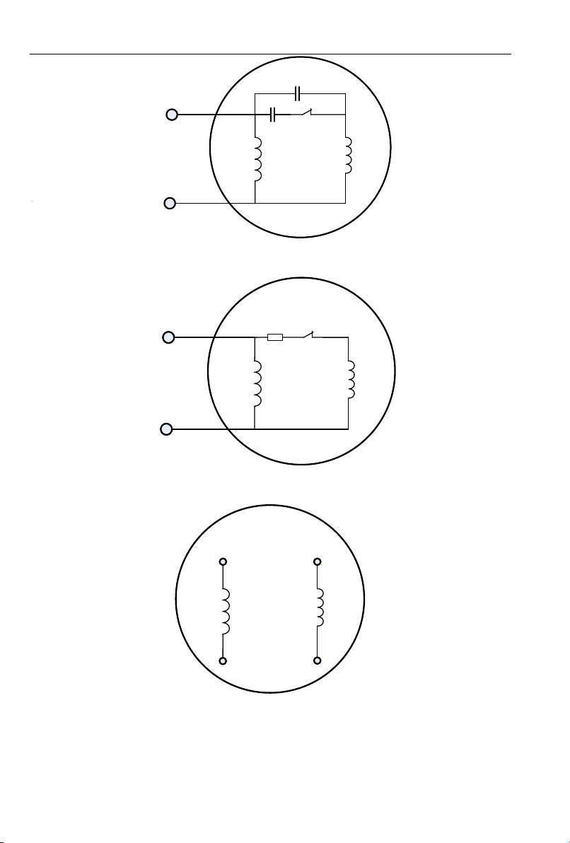
Internal wiring of single phase motor with double capacitors is as below:
Figure 2-7 Starting mode: Internal wiring of motor with single capacitor
- 15 -
Page 16
PV series Solar Pumping Inverter
Main winding
Secondary
winding
Starting
capacitor
U1
U2
Z1
Z2
M
220VAC
Centrifugal
switch
Running
capacitor
Main
winding
Secondary
winding
R
U1
U2
Z1
Z2
M
220VAC
Centrifugal
switch
Main winding
Secondary
winding
U1
U2
Z1
Z2
M
Figure 2-8 Internal wiring of motor with double capacitors
Resistor starting mode single phase motor, and internal wiring is as below:
Figure 2-9 Resistor starting mode: Internal wiring of motor
We can remove capacitors from above motors, and remaining 4 main and secondary winding
terminals as below:
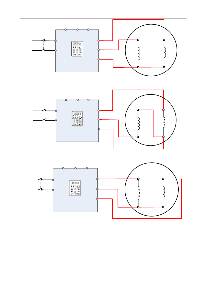
2.3.2 Wiring between VFD and motor
to the motor winding difference, motor forward wiring must be as below, if not cause motor too heat
Connect main and secondary winding of motor to inverter UVW, then inverter can work. But due
Figure 2-10 Main and secondary winding of motor
- 16 -
Page 17
PV series Solar Pumping Inverter
Main winding
Secondary
winding
U1
U2
Z1
Z2
M
(-) (+) PB
PV100
KM1
L1
L2
U
V
W
220VAC
Main
winding
Secondary
winding
U1
U2
Z1
Z2
M
(-) (+) PB
PV100
KM1
L1
L2
U
V
W
220VAC
Main winding
Secondary
winding
U1
U2
Z1
Z2
M
(-) (+) PB
PV200
KM1
L1
L2
U
V
W
220VAC
Motor reverse can’t be completed through parameter setting of inverter or change any two
Figure 2-11 Forward wiring between PV100 VFD and motor
phase wirings, motor reverse wiring must be as below:
Figure 2-12 Reverse wiring between PV100 VFD and motor
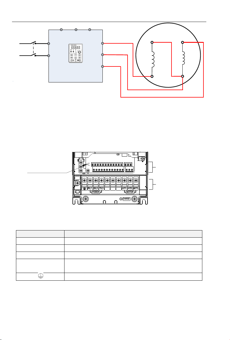
Motor forward and reverse wiring of 0.75Kw/220V PV200 is same with PV100, and wiring of
PV200 above 0.75kW are as below:
Figure 2-13 Forward wiring between VFD PV200 (Above 0.75Kw) and motor
- 17 -
Page 18
PV series Solar Pumping Inverter
Main
winding
Secondary
winding
U1
U2
Z1
Z2
M
(-) (+) PB
PV200
KM1
L1
L2
U
V
W
220VAC
Control circuit
terminals
Main circuit
terminals
Upload and
download interfaces
PB
(+)
(-)
RFI
Terminal Label
Description
R/L1、S/L2、T/L3
AC Power Input Terminal, connected to three-phase 380V AC power.
U/T1、V/T2、W/T3
Inverter AC output terminal, connected to three-phase AC motor
(+)、(-)
Respectively to be positive and negative terminal of internal DC bus
PB
Braking resistor connection terminals, one end connected to (+), the
other end of PB.
Ground terminal, connected to the earth.
Figure 2-14 Reverse wiring between VFD PV200 (Above 0.75Kw) and motor
After wiring completed, need to set F08.00=2.
2.4 Product Terminal Configuration
2.4.1 Main Circuit Terminals
0.75~200KW main circuit terminals
Figure 2-15 0.75~200kW Main Circuit Terminal Diagram
Table 2-1 Functions of Inverter Main Circuit Terminals
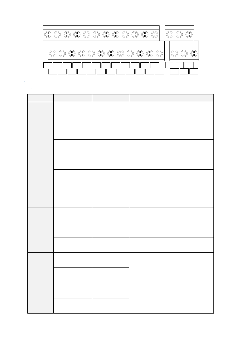
2.4.2 Control Circuit Terminals
- 18 -
Page 19
PV series Solar Pumping Inverter
DI1
+24V
DI2
PLC
DI3
COM
DI4
DI5
COM
DI6
Y1
Y2
+10V
R1A R1B
R1C
R2A R2B
R2C
AO1
AI1
GND
AI2
485+
AI3
485-
PE
DI7/HI
AO2
GND
Type
Terminal Symbol
Terminal Name
Description
Power
Supply
+10V-GND
+10V Power
Supply
Output +10V Power Supply, Maximum
Output Current: 10mA. Generally use for
power supply of external potentiometer,
resistance range of potentiometer: 1~
5kΩ
+24V-COM
24V Power
Supply
Output +24V power supply, generally use
for power supply of digital input/output
terminal and external sensor, maximum
output current: 200mA.
PLC
External Power
Input Terminal
Factory default in connection with +24V,
when using an external signal to drive
DI1~DI7, PLC need to be connected to
external power, and disconnected with
+24V power terminal.
Analog
Input
AI1-GND
Analog Input
Terminal 1
Input Range: DC 0~10V/0~20mA,
selected by AI1、AI2 toggle switches on
control board. Input Impedance: 250kΩ
for voltage input, 250Ω for current input.
AI2-GND
Analog Input
Terminal 2
AI3-GND
Analog Input
Terminal 3
Input voltage range: DC -10~+10V
Input Impedance: 250kΩ
Digital
Input
DI1- COM
Digital Input
Terminal 1
Maximum input frequency: 200Hz
Input Impedance: 2.4kΩ
Voltage Range of level-input:9V~30V
DI2- COM
Digital Input
Terminal 2
DI3- COM
Digital Input
Terminal 3
DI4- COM
Digital Input
Terminal 4
Figure 2-16Control Terminals Diagram
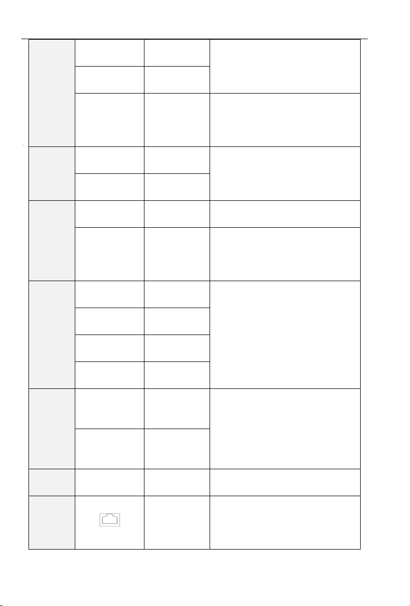
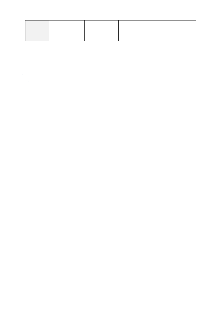
Table 2-2 PV200 Inverter Control Circuit Terminal Functions
- 19 -
Page 20
PV series Solar Pumping Inverter
DI5- COM
Digital Input
Terminal 5
DI6- COM
Digital Input
Terminal 6
DI7/HI-COM
Digital Input
Terminal 7 or
high-speed
pulse input
Besides the features of DI1~DI6, DI7 also
can be the channel of high-speed pulse
input. Maximum input frequency: 100kHz.
Analog
Output
AO1-GND
Analog Output
Terminal 1
Output range:DC 0~10V/0~20mA,
selected by A01、A02 toggle switches on
control board. Impedance required≥10kΩ
AO2-GND
Analog Output
Terminal 2
Digital
Output
Y1-COM
Open Collector
Output 1
Voltage Range: 0~24V
Current Range: 0~50mA
Y2/HO-COM
Open Collector
Output 2or
high-speed
pulse output
Apart from Y1 characteristics, Y2 also
can be the channel of high-speed pulse
input. Maximum output frequency:
100kHz.
Relay
Output
R1A-R1C
normal open
terminal
Contact driving ability:
AC250V,3A,COSØ=0.4。
DC 30V,1A
R1B-R1C
normal close
terminal
R2A-R2C
normal open
terminal
R2B-R2C
normal close
terminal
485
Communi
cation
485+-485-
485
Communication
Terminals
Speed:
4800/9600/19200/38400/57600/115200b
ps.
RS485 toggle switch on control board,
setting the terminal matching-resister
GND
485
Communication
Shield Ground
Shielded
PE
Shield
Grounding
It’s use for grounding the shield of
terminal-wire
Aid
Interface
External
Keyboard
Interface
When connected to operation board, the
longest communication distance is up to
50m, adopt the standard network cable
(RJ45)
- 20 -
Page 21
PV series Solar Pumping Inverter
UP/DOWNLOAD
Parameter
Copy Card
Interface
Note:the common termial (COM) of the PV100 series is GND.
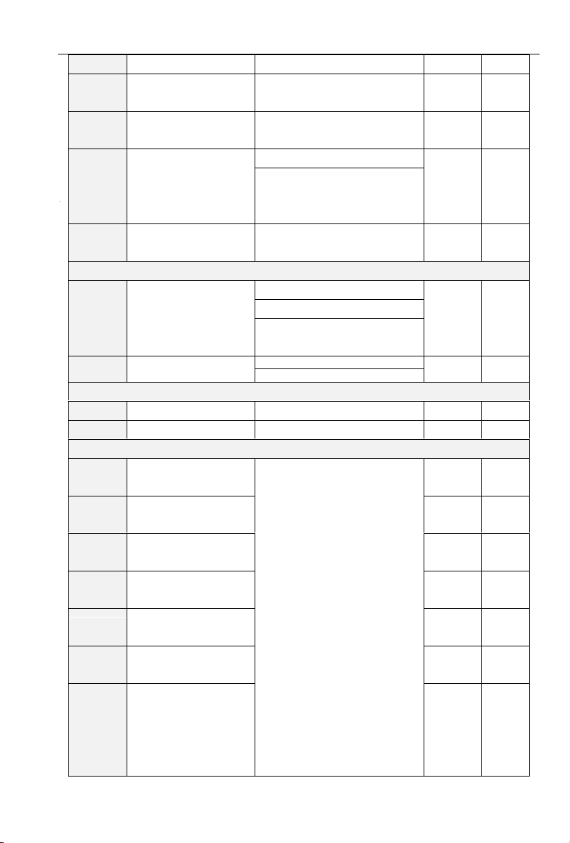
- 21 -
Page 22
PV series Solar Pumping Inverter
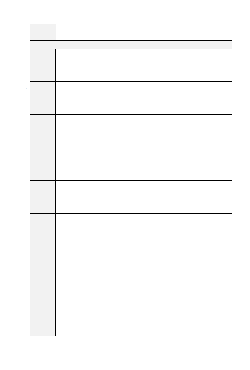
Function
Code
Name
Descriptions
Default
Value
Attribu
te
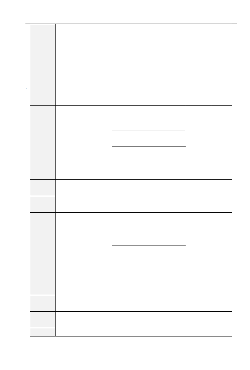
F00 Group: System Parameters
F00.00
User Password
0~65535
0
×
F00.04
Default Value Control
0:Null
0
×
1:Factory Reset(Excluding
motor parameters)
2: Clear the record information of
fault
3:Backup user’s current
parameters
4:User’s backup parameters
were restored
F00.13
Carrier frequency
0.700~16.000kHz
Model
defined
△
F00.18
Fan control
0: Run at power-on
1
×
1: Fan working during running
F00.20
Inverter rated power
0.2~710.0kW
Model
defined
⊙
F00.21
Inverter rated voltage
60~660V
Model
defined
⊙
F00.22
Inverter rated current
0.1~1500.0A
Model
defined
⊙
F00.23
Software version
0.00~655.35
Model
defined
⊙
F00.24
Dealer password
0~65535
0
×
F00.25
Setting operation time
0~65535h(0: Invaild)
0h
×
F01 Group: Frequency Given
F01.01
Master Frequency
Command Source
0:Master digital setting (F01.02)
1
×
1: keypad potentiometer
2: Analog input AI1
3: Communication
4: Multi-reference
5: PLC
6: Process PID output
7: X7/HI pulse input
8:AI2
9:AI3
F01.02
Digital Setting of Master
Frequency
0.00~Fmax
0.00Hz
△
F01.08
Maximum Frequency
20.00~600.00Hz
50.00Hz
×
Chapter Three Function Parameters
3.1 The Basic Function Parameters
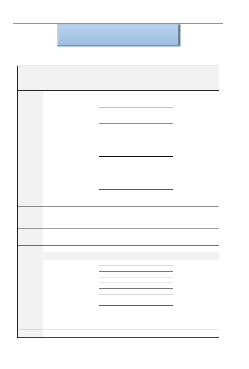
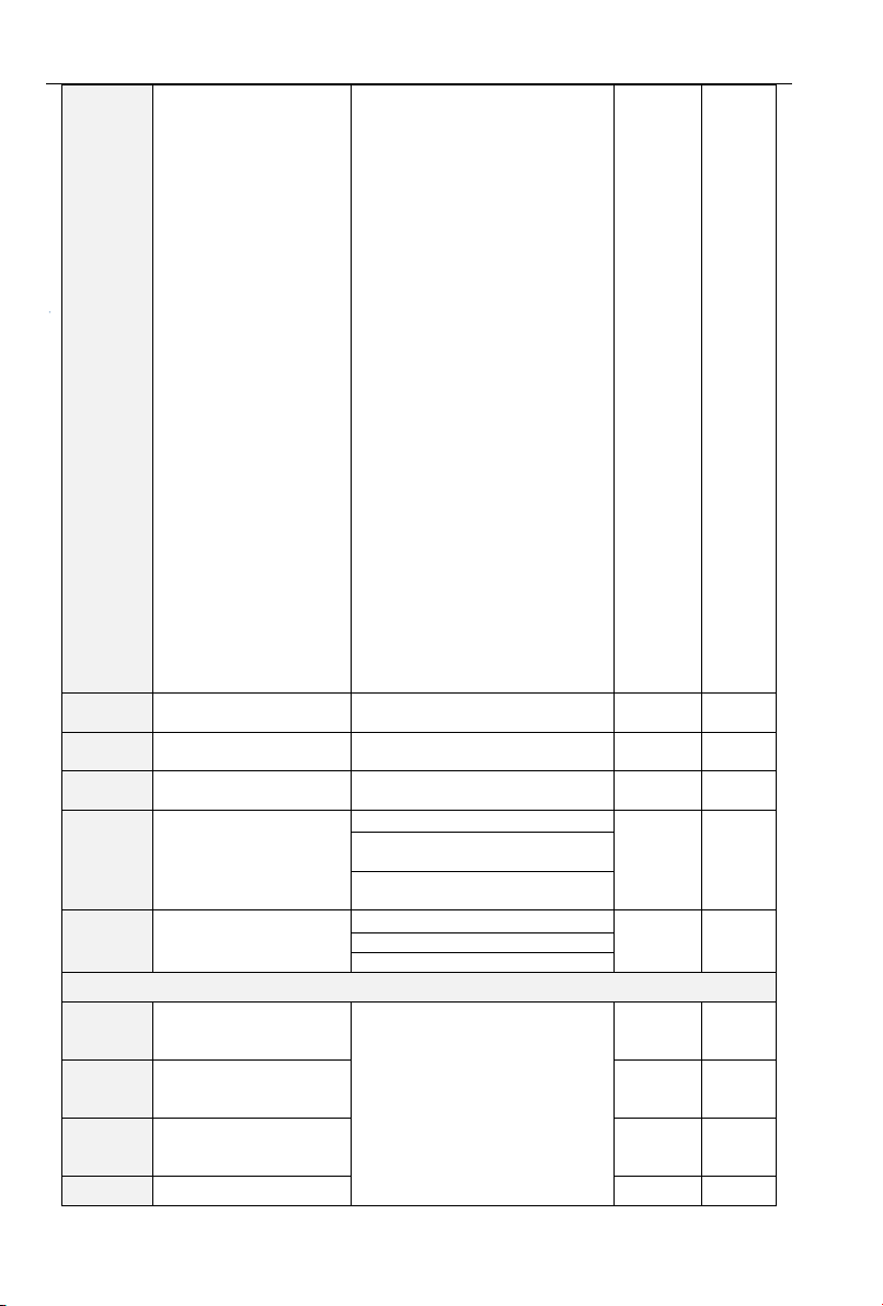
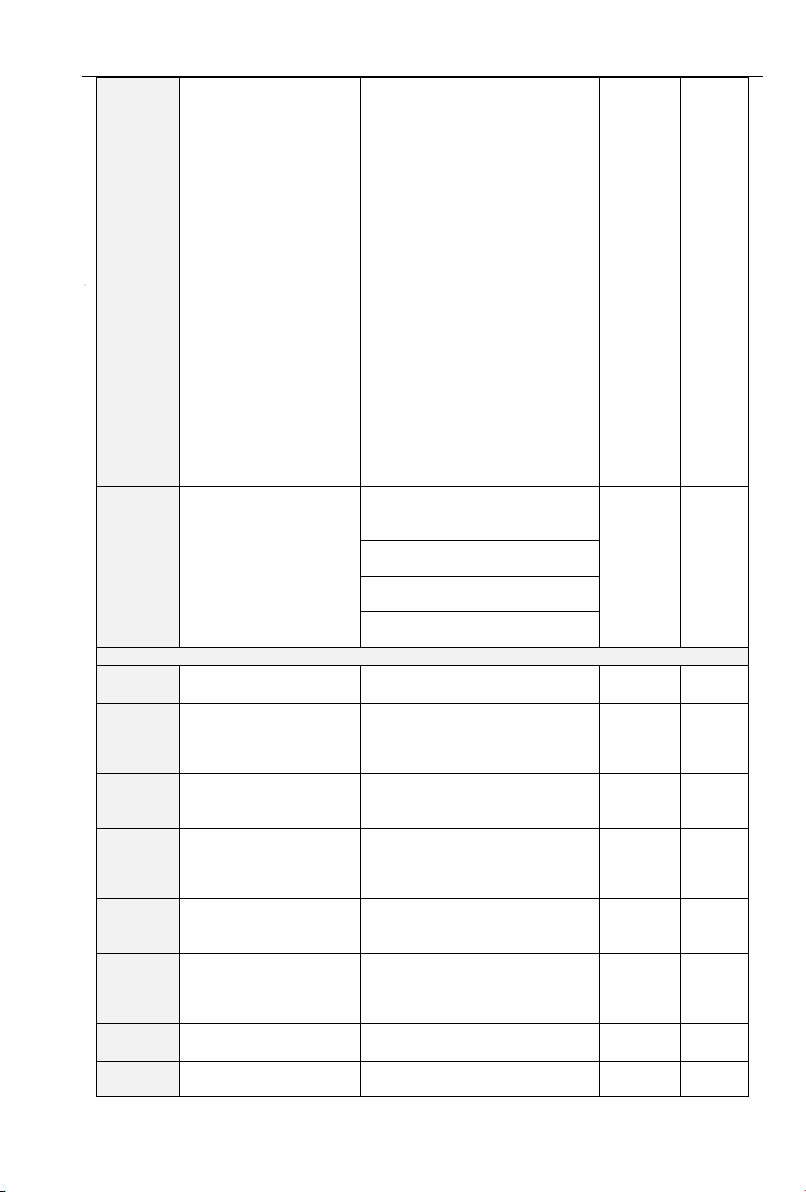
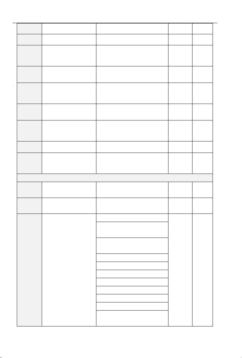
Table 3-1 Basic Function Parameters
- 22 -
Page 23
PV series Solar Pumping Inverter
(Fmax)
F01.09
Upper Limit
Frequency(Fup)
Fdown~Fmax
50.00Hz
×
F01.10
Lower Limit
Frequency(Fdown)
0.00~Fup
0.00Hz
×
F01.11
Given frequency lower
than the frequency
control of lower limit
0:Run by the lower frequency
0
×
1:After running time of lower
limit frequency, it will run on
speed of 0.
F01.12
Running time of lower
limit frequency
0.0~6000.0s
60.0s
×
F02 Group: Control of Run/Stop
F02.00
Command Source
Selection of Run/Start
0:Operation Panel(LED off)
1
×
1:External Terminal(LED on)
2:Computer Communications
(LED flash)
F02.12
Stop mode
0: Ramp to stop
0
×
1: Coast to stop
F03 Group: Acceleration/Deceleration Time
F03.00
Acceleration Time 1
0.0~6000.0s
15.0s
△
F03.01
Deceleration Time 1
0.0~6000.0s
1.0s
△
F04 Group: Digital Input Terminals
F04.00
Terminal DI1 Function
Selection
0:No function
1:Running forward (FWD)
2:Running reverse (REV)
3:Three-wire control
4:JOG forward
5:JOG reverse
6:Coast to stop
7:Fault reset (RESET)
8:Running suspended
9:External fault input
10:Terminal UP
11:Terminal DOWN
12:UP/DOWN (including ∧/∨
key) adjustment clear
13:Multi-step frequency terminal
1
14:Multi-step frequency terminal
2
15:Multi-step frequency terminal
3
16:Multi-step frequency terminal
4
17:Accel/Decel time determinant
1
18:Accel/Decel time determinant
2
1
×
F04.01
Terminal DI2 Function
Selection
51 × F04.02
Terminal DI3 Function
Selection
52 × F04.03
Terminal DI4 Function
Selection
52
F04.04
Terminal DI5 Function
Selection
0 F04.05
Terminal DI6 Function
Selection
0
F04.06
Terminal DI7 Function
Selection
0
×
- 23 -
Page 24
PV series Solar Pumping Inverter
19:Accel/Decel disabled(ramp
stop not inclusive)
20:Switch to auxiliary speed
setting
21:PLC status reset
22:Simple PLC paused
23:Simple PLC paused
24:PID adjustment direction
25:PID integration paused
26:PID parameter switch
27:Swing frequency
pause(output the
currentfrequency)
28:Swing frequency reset(output
the central frequency)
29:Run command switched to
keypad contro
30:Run command switched to
terminal control
31:Run command switched to
communication control
32:Count input
33:Count clear
34:Length count
35:Length clear
36:DC brake input command at
stop
37~49:reserved
50:Special Machine Enabled
51:Solar Panels Power Enabled
52: Overtank or dry run switch
dormancy
F04.10
Filtering time of digital
input terminal
0.000~1.000s
0.010s
△
F04.11
Delay time of terminal
DI1
0.0~300.0s
0.0s
△
F04.12
Delay time of terminal
DI2
0.0~300.0s
0.0s
△
F04.13
Terminal DI1~DI5
positive/negative logic
DI5、DI4、DI3、DI2、DI1
00000
×
0: Positive logic(Terminals are
on at 0V/off at 24V)
1: Negative Logic (Terminals
are off at 0V/on at 24V)
F04.14
Terminal DI6~AI3
positive/negative logic
AI3、AI2、AI1、DI7、DI6
00000
×
0: Positive logic
1: Negative Logic
F05 Group: Digital Output Terminal
F05.00
Y1 Output Function
Selection
0: No output
1: Drive is running
2: Fault output
3: Frequency-level detection
FDT1 output
4: Frequency-level detection
FDT2 output
5: Drive in 0Hz running 1(no
output at stop)
6: Drive in 0Hz running 2(output
1
×
F05.01
Y2 Output Function
Selection
2 F05.02
Relay R1 Output
Function Selection
30
F05.03
Relay R2 Output
11
×
- 24 -
Page 25
PV series Solar Pumping Inverter
Function Selection
at stop)
7: Upper limit frequency attained
8: Lower limit frequency attained
9: Frequency attained
10: Inverter is ready to work
11: Drive (motor) overloaded
alarm
12: Inverter overheat warning
13: Current running time attained
14: Accumulative power-on time
attained
15: Consecutive running time
attained
16: PLC cycle completed
17: Set count value attained
18: Designated count value
attained
19: Length attained
20: Under load alarm
21:Brake
22~29:reserved
30: Automatic switch of grid
power and solar power
F05.08
Enabled state of digital
output
Unit's place: Y1
0: Positive logic
1: Negative logic
0000
×
Decade: Y2 (same as unit's
place)
Hundreds place: Relay 1 output
(same as unit's place)
Thousands place: Relay 2 output
(same as unit's place)
Group F06 Analog and Pulse Input
F06.00
Minimum input of curve
AI1
0.0%~input of inflection point1
of curve AI1
0.0%
△
F06.01
Set value
corresponding
to minimum input of
curve AI1
-100.0~100.0%
0.0%
△
F06.02
Input of inflection point
1 of curve AI1
Minimum input of curve AI1~
Input of inflection point 2 of curve
AI1
100.0%
△
F06.03
Set value
corresponding
to input of inflection
point 1 of curve AI1
-100.0~100.0%
100.0%
△
F06.04
Input of inflection point
2 of curve AI1
Input of inflection point 1 of curve
AI1~Maximum input of curve
AI1
100.0%
△
F06.05
Set value
corresponding
to input of inflection
point 2 of curve AI1
-100.0~100.0%
100.0%
△
F06.06
Maximum input of curve
AI1
Input of inflection point 2 of curve
AI1~100.0%
100.0%
△
F06.07
Set value
corresponding
-100.0~100.0%
100.0%
△
- 25 -
Page 26
PV series Solar Pumping Inverter
to maximum input of
curve AI1
F06.08
Minimum input of curve
AI2
0.0%~input of inflection point1
of curve AI2
0.0%
△
F06.09
Set value
corresponding
to minimum input of
curve AI2
-100.0~100.0%
0.0%
△
F06.10
Input of inflection point
1 of curve AI2
Minimum input of curve AI1~
Input of inflection point 2 of curve
AI2
100.0%
△
F06.11
Set value
corresponding
to input of inflection
point 1 of curve AI2
-100.0~100.0%
100.0%
△
F06.12
Input of inflection point
2 of curve AI2
Input of inflection point 1 of curve
AI2~ Maximum input of curve
AI2
100.0%
△
F06.13
Set value
corresponding
to input of inflection
point 2 of curve AI2
-100.0~100.0%
100.0%
△
F06.14
Maximum input of curve
AI2
Input of inflection point A of
curve AI2~100.0%
100.0%
△
F06.15
Set value
corresponding
to maximum input of
curve AI2
-100.0~100.0%
100.0%
△
F07 Group: Analog and Pulse Output
F07.00
AO1 Output Function
Selection
0:No Output
1
×
F07.01
AO2 Output Function
Selection
1:Output Frequency
2
×
F07.02
Y2/HO Output Function
Selection
(When used as HO)
2:Set Frequency
1
×
3:Output Current(Inverter Rated
Current)
4:Output Voltage(Inverter Rated
Voltage)
5:Output Power
6:Bus Voltage
7:+10V
8:Keyboard Potentiometer
9:AI1
10:AI2
11:AI3
12:HI Input(100.0%
corresponds 100.00kHz)
- 26 -
Page 27
PV series Solar Pumping Inverter
13:Output Torque(Absolute
Value of the Torque)
F08 Group: Motor 1 Basic Parameters
F08.00
Motor type
0:Three phase asynchronous
motor
2:Single phase asynchronous
motor
0
×
F08.01
Motor 1 Rated Power
0.10~600.00kW
Type
fixed
×
F08.02
Motor 1 Rated Voltage
60~660V
Type
fixed
×
F08.03
Motor 1 Rated Current
0.1~1500.0A
Type
fixed
×
F08.04
Motor 1 Rated
Frequency
20.00~Fmax
Type
fixed
×
F08.05
Motor 1 Rated
Rotational Speed
1~30000
Type
fixed
×
F08.06
Motor 1 Wirings
0:丫
Type
fixed
×
1:Δ
F08.07
Motor 1 Rated Power
Factor
0.50~0.99
Type
fixed
×
F08.08
Asynchronous Motor 1
Stator Resistance R1
0.001~65.535Ω
Type
fixed
×
F08.09
Asynchronous Motor 1
Rotor Resistance R2
0.001~65.535Ω
Type
fixed
×
F08.10
Asynchronous Motor 1
Leakage Inductance
0.001~65.535mH
Type
fixed
×
F08.11
Asynchronous Motor 1
Mutual Inductance
0.1~6553.5mH
Type
fixed
×
F08.12
Asynchronous Motor 1
No-load Field Current
0.1~1500.0A
Type
fixed
×
F08.13
Asynchronous Motor
1
field-weakening
coefficient 1
0.0~100.0
87%
×
F08.14
Asynchronous Motor
1 field-weakening
coefficient 2
0.0~100.0
75%
×
- 27 -
Page 28
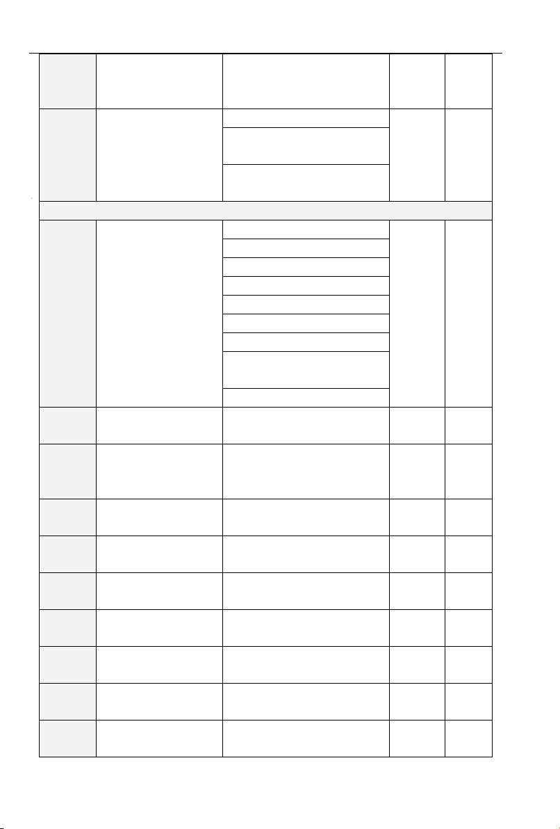
PV series Solar Pumping Inverter
F08.15
Asynchronous Motor
1 field-weakening
coefficient 3
0.0~100.0
70%
×
F08.30
Parameters
Self-identification
0:Null
0
×
1:Asynchronous Motor Static
Self-identification
2:Asynchronous Motor Rotation
Self-identification
F09 Group: Motor 1VF Curve
F09.00
Motor 1VF Curve
Setting
0:Straight Line V/F
0
×
1:Multipoint V/F
2:1.2th power of the V/F curve
3:1.4th power of the V/F curve
4:1.6th power of the V/F curve
5:1.8th power of the V/F curve
6:2.0th power of the V/F curve
7:VF Completed Separation
Mode
8:VF Semi-separation Mode
F09.01
Motor 1 Torque Boost
0.0~30.0% 0.0%:(Auto
Torque Boost)
0.0%
△
F09.02
Motor 1 Cut-off
frequency of
Torque-Boost
0.00~Maximum Frequency
50.00Hz
△
F09.03
Motor 1Multipoint V/F
frequency points 1
0.00~F09.05
0.00Hz
△
F09.04
Motor 1 Multipoint VF
Voltage Points 1
0.0~100.0
0.0%
△
F09.05
Motor 1 Multipoint V/F
frequency points 2
F09.03~F09.05
5.00Hz
△
F09.06
Motor 1 Multipoint VF
Voltage Points 2
0.0~100.0
14.0%
△
F09.07
Motor 1 Multipoint V/F
frequency points 3
F09.05~F09.09
25.00Hz
△
F09.08
Motor 1 Multipoint VF
Voltage Points 3
0.0~100.0
50.0%
△
F09.09
Motor 1 Multipoint V/F
frequency points 4
F09.07~Rated Frequency of
Motor
50.00Hz
△
- 28 -
Page 29
PV series Solar Pumping Inverter
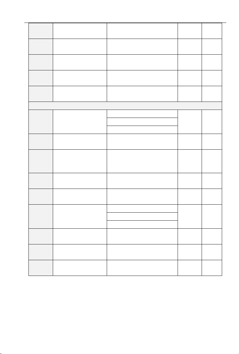
F09.10
Motor 1 Multipoint VF
Voltage Points 4
0.0~100.0 Ue=100.0%
100.0%
△
F09.11
VF Slip Compensation
Gain
0.0~300.0%
80.0%
△
F09.12
VF Stator Voltage-drop
Compensation Gain
0.0~200.0%
100.0%
△
F09.13
VF Excitation
Compensation Gain
0.0~200.0%
100.0%
△
F09.14
VF Oscillation
Suppression Gain
0.0~300.0%
100.0%
△
F11 Group: Fault and Protection
F11.00
Control of Overcurrent
Stall
0:Null
2
×
1:Overcurrent Stall Mode 1
2: Overcurrent Stall Mode 2
F11.01
Protection current of
Overcurrent Stall
100.0~200.0%
150.0%
×
F11.02
Frequency Fall Time of
Constant Speed
Overcurrent Stall
0.0~6000.0s (Mode 1 is Active)
5.0s
△
F11.03
Overcurrent Stall Mode
2 Proportion Coefficient
0.1~100.0%
3.0%
△
F11.04
Overcurrent Stall Mode
2 Integral Time
0.00~10.00s (0.00:Integral
Invalid)
10.00s
△
F11.05
Control of Overvoltage
Stall
0:Null
0
×
1:Overvoltage Stall Mode 1
2: Overvoltage Stall Mode 2
F11.06
Voltage of Overvoltage
Stall
600~800V
700V
×
F11.07
Overvoltage Stall Mode
2 Proportion Coefficient
0.1~100.0%
3.0%
△
F11.08
Overvoltage Stall Mode
2 Integral Time
0.00~10.00s (0.00:Integral
Invalid)
10.00s
△
- 29 -
Page 30
PV series Solar Pumping Inverter
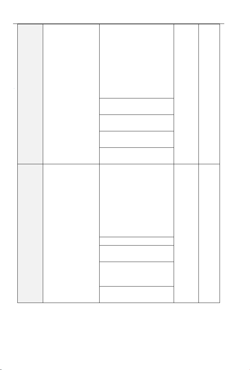
F11.10
Selection of failsafe
action 1
Ones: Bus Under voltage
Protection(Err07)
0:Reporting faults and freely
parking
1:Alarming and parking by
deceleration mode
2:Alarm and continue running
on fault frequency
3:Protection Invalid
03000
×
Tens: Input Phase-protection
(Err09)
Hundreds: Output
Phase-protection (Err10)
Thousands: Motor Overload
Protection (Err10)
Myriabit: Inverter Overload
Protection(Err12)
F11.11
Selection of failsafe
action 2
Ones: External Input
Failure-protection(Err13)
0:Reporting faults and freely
parking
1:Alarming and parking by
deceleration mode
2:Alarm and continue running
on fault frequency
3:Protection Invalid
00000
×
Tens: Memory Failure (Err15)
Hundreds: 485 communication
timeout (Err18)
Thousands: PID feedback
disconnection when running
(Err19)
Myriabit: running time arrives
(Err20)
- 30 -
Page 31
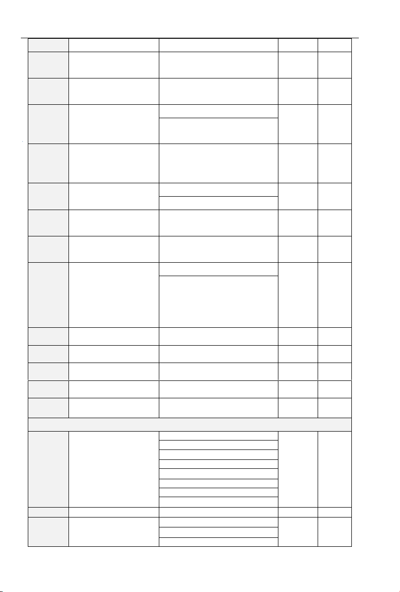
PV series Solar Pumping Inverter
F11.12
Selection of failsafe
action 3
Ones: Disconnection Fault of
Temperature Sensor(Err24)
0:Reporting faults and freely
parking
1:Alarming and parking by
deceleration mode
2:Alarm and continue running
on fault frequency
3:Protection Invalid
00
×
Tens: Inverter load-lost(Err25)
F11.14
When failure, frequency
selection of continue
running
0:Running on current setting
frequency
0
×
1:Running on setting frequency
2:Running on upper-limit
frequency
3:Running on lower-limit
frequency
4:Running on abnormal
spare-frequency
F11.15
Abnormal Alternate
Frequency
0.00~Fmax
0.00Hz
×
F11.17
Protection time of Motor
Overload
30.0~300.0s
60.0s
×
F11.18
Selection of Overload
Pre-warning
Ones: selection of detection
0:always detection
1:detection only when constant
speed
00
×
Tens: condition selection of
detection
0:responds to rated current of
motor
1:responds to rated current of
inverter
F11.19
Detectable Level of
Overload Pre-alarm
20.0~200.0%
130.0%
×
F11.20
Detectable Time of
Overload Pre-alarm
0.1~60.0s
5.0s
×
F11.21
Pre-alarm Temperature
50.0~100.0℃
70.0℃
×
- 31 -
Page 32
PV series Solar Pumping Inverter
of Inverter Overheat
F11.22
Detectable Level of
load-loss
5.0~100.0%
20.0%
×
F11.23
Detectable Time of
load-loss
0.1~60.0s
5.0s
×
F11.24
Operation selection of
instantaneous power
failure
0:Null
0
×
1:Valid
F11.25
Frequency deceleration
time of instantaneous
power failure
0.0~6000.0s
5.0s
△
F11.26
Selection control of fast
current-limit
0:Prohibit
0
×
1:Permit
F11.27
Auto-Reset Times of
failure
0~20 0 ×
F11.28
Auto-Reset Interval of
failure
0.1~100.0s
1.0s
×
F11.29
During the fault
auto-resetting, program
Of switch output
terminal , is action
selection of output fault
0:No action
0
×
1:Action
F11.30
Instantaneous power
off bus voltage
60.0%~Recovery voltage
80.0%
△
F11.31
Instantaneous power off
recovery voltage
Power off voltage~100.0%
85.0%
△
F11.32
Instantaneous power off
voltage detection time
0.01~10.00s
0.10s
△
F11.33
Instantaneous power off
Kp
0.1~100.0%
40.0%
△
F11.34
Instantaneous power off
integration time Ti
0.00 ~ 10.00s ( 0.00 :
Integration invalid)
0.10s
△
Group F13 Process PID
F13.00
PID setting
0: F13.01 digital setting
0
×
1:keypad potentiometer
2:AI1
3: Communication
4:Multi-Reference
5: DI7/HI pulse input
6: AI2
7:AI3
F13.01
PID digital setting
0.0~100.0%
50.0%
△
F13.02
PID feedback
0:AI1
0
×
1:AI2
2: Communication
- 32 -
Page 33
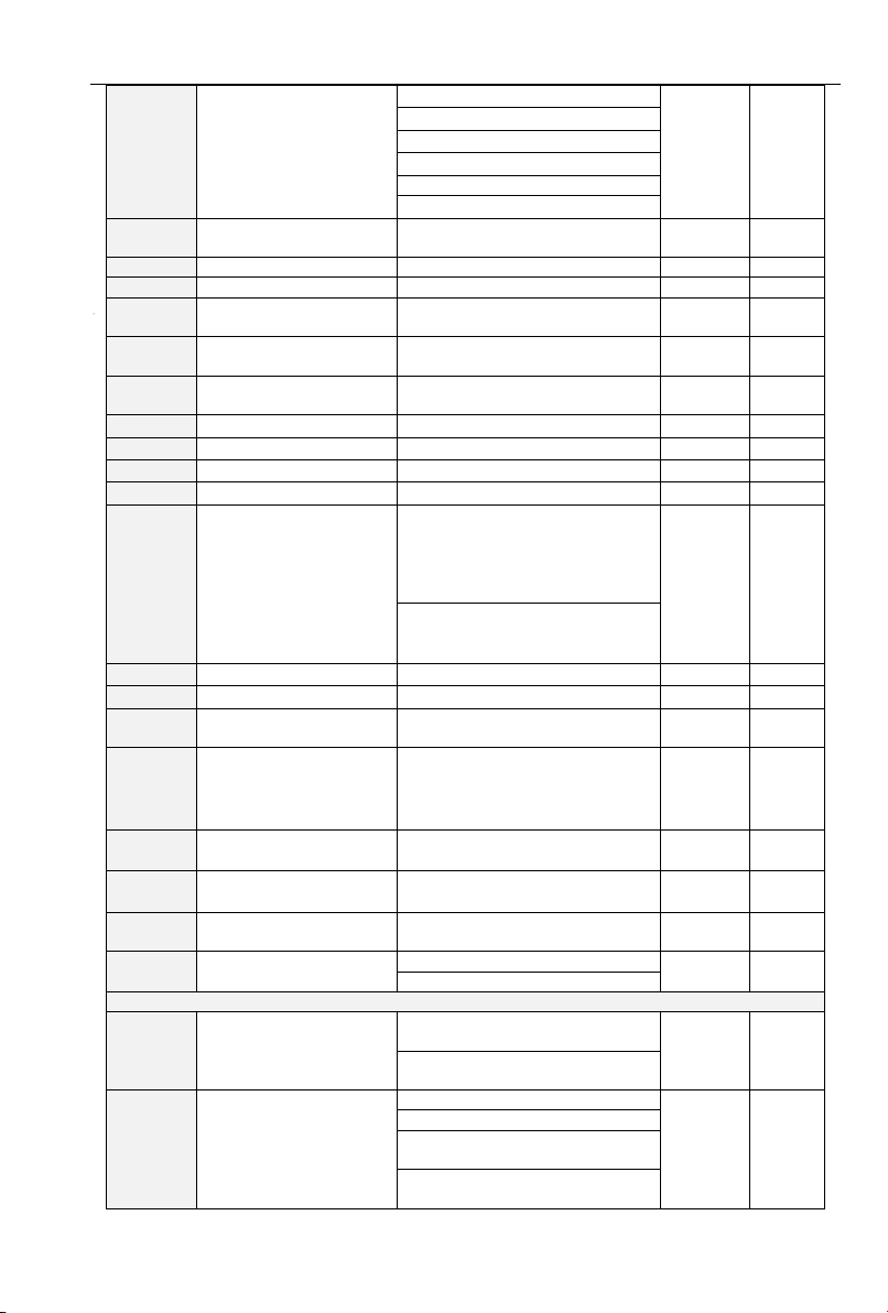
PV series Solar Pumping Inverter
3:AI1+AI2
4:AI1-AI2
5:Max{AI1,AI2}
6:Min{AI1,AI2}
7: DI7/HI pulse input
8:AI3
F13.03
PID setting feedback
range
0~60000
1000
△
F13.04
PID action direction
0: Forward action
0 × 1: Reverse action
F13.05
Filtering time of PID
setting
0.000~10.000s
0.000s
△
F13.06
Filtering time of PID
feedback
0.000~10.000s
0.000s
△
F13.07
Filtering time of PID
output
0.000~10.000s
0.000s
△
F13.08
Proportional gain Kp1
0.0~100.0
1.0 △ F13.09
Integration time Ti1
0.01~10.00s
0.10s
△
F13.10
Differential time Td1
0.000~10.000s
0.000s
△
F13.17
PID offset limit
0.0~100.0%
1.0%
×
F13.18
PID integral property
Unit's digit (Whether to stop
integral operation when the
output reaches the limit)
0: Continue integral operation
1: Stop integral operation
00
×
Ten's digit (Integral separated)
0: Invalid
1: Valid
F13.19
PID differential limit
0.0~100.0%
0.5%
×
F13.20
PID initial value
0.0~100.0%
0.0%
×
F13.21
Holding time of PID
initial value
0.0~6000.0s
0.0s
×
F13.22
PID output frequency
upper limit
PID output frequency lower
limit~100.0%(100.0%
corresponds to maximum
frequency )
100.0%
×
F13.23
PID output frequency
lower limit
–100.0%~PID output frequency
lower limit
0.0%
×
F13.24
Detection value of
PID feedback loss
0.1~100.0%
0.0%: Not judging feedback loss
0.0%
×
F13.25
Detection time of
PID feedback loss
0.0~30.0s
1.0s
×
F13.26
PID operation at stop
0: No PID operation at stop
0
×
1: PID operation at stop
Group F16 Keys and Display of Keypad Parameters
F16.01
Function of STOP/RST
key
0: STOP/RST key valid only
when under keypad control
1
×
1: STOP/RST key valid under
any run command source
F16.02
Keys locked option
0: Not locked
0
×
1: Full locked
2: Keys locked other than RUN,
STOP/RST
3: Keys locked other than
STOP/RST
- 33 -
Page 34
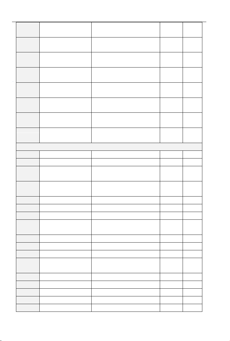
PV series Solar Pumping Inverter
F16.03
LED displayed
parameters setting 1 on
running status
0~99(correspond U00.00~
U00.99)
0
△
F16.04
LED displayed
parameters setting 2 on
running status
0~99(correspond U00.00~
U00.99)
6 △ F16.05
LED displayed
parameters setting 3 on
running status
0~99(correspond U00.00~
U00.99)
3 △ F16.06
LED displayed
parameters setting 4 on
running status
0~99(correspond U00.00~
U00.99)
2
△
F16.07
LED displayed
parameters setting 1 on
stop status
0~99(correspond U00.00~
U00.99)
1
△
F16.08
LED displayed
parameters setting 2 on
stop status
0~99(correspond U00.00~
U00.99)
6
△
F16.09
LED displayed
parameters setting 3 on
stop status
0~99(correspond U00.00~
U00.99)
15 △ F16.10
LED displayed
parameters setting 4 on
stop status
0~99(correspond U00.00~
U00.99)
16
△
U00 Group: Status Monitoring
U00.00
Output Frequency
0.00~Fup
0.00Hz
⊙
U00.01
Setting Frequency
0.00~Fmax
0.00Hz
⊙
U00.02
Actual value of output
voltage
0~660V
0.0V
⊙
U00.03
Actual value of output
current
0.0~3000.0A
0.0A
⊙
U00.04
Output Power
-3000.0~3000.0kW
0.0kW
⊙
U00.05
Output Rotation-rate
0~60000rpm
0rpm
⊙
U00.06
DC Bus Voltage
0~1200V
0V
⊙
U00.07
Synchronization
Frequency
0.00~Fup
0.00Hz
⊙
U00.08
PLC Stage
1~15 1 ⊙
U00.09
Program Running Time
0.0~6000.0s(h)
0.0s(h)
⊙
U00.10
PID Given
0~60000
0
⊙
U00.11
PID Arithmetic
Feedback
0~60000
0
⊙
U00.12
DI1~DI5 Input Status
DI5 DI4 DI3 DI2 DI1
00000
⊙
U00.13
DI6~DI7 Input Status
DI7 DI6
00
⊙
U00.14
Digital Output Status
R2 R1 Y2 Y1
0000
⊙
U00.15
AI1 Input
0.0~100.0%
0.0%
⊙
U00.16
AI2 Input
0.0~100.0%
0.0%
⊙
- 34 -
Page 35
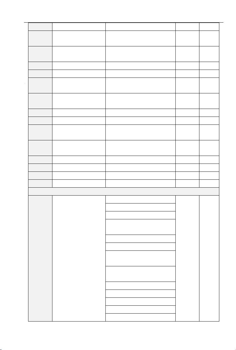
PV series Solar Pumping Inverter
U00.17
AI3 Input
-100.0~100.0%
0.0%
⊙
U00.18
Keyboard
Potentiometer Input
0.0~100.0%
0.0%
⊙
U00.19
HI Pulse Input
Frequency
0.00~100.00kHz
0.00kHz
⊙
U00.20
A01 Output
0.0~100.0%
0.0%
⊙
U00.21
A02 Output
0.0~100.0%
0.0%
⊙
U00.22
HO Pulse Output
Frequency
0.00~100.00kHz
0.00kHz
⊙
U00.23
Temperature of Inverter
Module
-40.0℃~120.0℃
0.0℃
⊙
U00.24
The Power-on Time
0~65535min
0min
⊙
U00.25
The Running Time
0~6553.5min
0.0min
⊙
U00.26
Cumulative Power-on
Time
0~65535h
0h ⊙ U00.27
Cumulative Running
Time
0~65535h
0h
⊙
U00.28
Actual Count Value
0~65535
0
⊙
U00.29
Actual Length Value
0~65535m
0m
⊙
U00.30
Line Speed
0~65535m/min
0m/Min
⊙
U00.31
Output Torque
0.0~300.0%
0.0%
⊙
U01 Group: Failure Record
U01.00
Current Fault Category
Err00: No Fault
Err00
⊙
Err01:Accelerated Overcurrent
Err02:Decelerated Overcurrent
Err03:Constant Speed
Overcurrent
Err04:Accelerated Overvoltage
Err05:Decelerated Overvoltage
Err06:Constant Speed
Overvoltage
Err07:Bus Under voltage
Protection
Err08:Short Circuit Protection
Err09:Input Open Phase
Err10:Output Open Phase
Err11:Motor Overload
Err12:Inverter Overload
- 35 -
Page 36
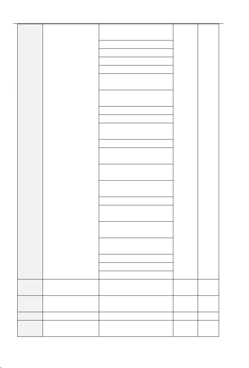
PV series Solar Pumping Inverter
Err13:Fault protection of
external input
Err14:Overheat
Err15:Memory Failure
Err16:Cancel Auto-tuning
Err17:Auto-tuning Failure
Err18:485 Communication
Timeout
Err19:PID feedback
disconnection on runtime
Err20:running time arrives
Err21:Parameter Upload Error
Err22:Parameter Download
Error
Err23:Braking Unit Failure
Err24:Disconnection fault of
temperature sensor
Err25:Lose-load failure/alarm of
Inverter
Err26:with-wave current limit
fault
Err27:Soft-start relay unclosed
Err28:EEPROM Version
Incompatible
Err29:Overcurrent tested by
hardware
Err30:Overvoltage tested by
hardware
Err32: Hydraulic Probe Failure
Arn33:Pre-warning of weak light
Arn34:Pre-warning of full-water
U01.01
Output frequency of the
current fault
0.00~Fup
0.00Hz
⊙
U01.02
Output current of the
current fault
0.0~3000.0A
0.0A
⊙
U01.03
c of the current fault
0~1200V
0V
⊙
U01.04
Cumulative runtime of
the current fault
0~65535h
0h
⊙
- 36 -
Page 37
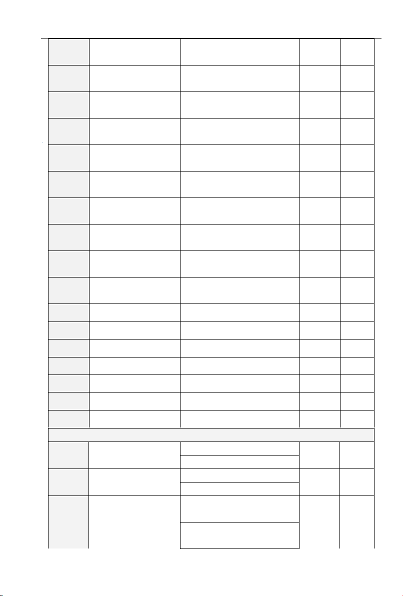
PV series Solar Pumping Inverter
U01.05
Former one fault
category
Like the latest one fault record
Err00
⊙
U01.06
Output frequency of the
former one fault
0.00~Fup
0.00Hz
⊙
U01.07
Output current of the
former one fault
0.0~3000.0A
0.0A
⊙
U01.08
Bus Voltage of the
former one fault
0~1200V
0V ⊙ U01.09
Cumulative runtime of
the former one fault
0~65535h
0h
⊙
U01.10
Former two fault
categories
Like the latest one fault record
Err00
⊙
U01.11
Output frequency of the
former two faults
0.00~Fup
0.00Hz
⊙
U01.12
Output current of the
former two faults
0.0~3000.0A
0.0A
⊙
U01.13
Bus Voltage of the
former two faults
0~1200V
0V
⊙
U01.14
Cumulative runtime of
the former two faults
0~65535h
0h
⊙
U01.15
Previous 3 categories of
faults
The same with U01.00
Err00
⊙
U01.16
Previous 4 categories of
faults
The same with U01.00
Err00
⊙
U01.17
Previous 5 categories of
faults
The same with U01.00
Err00
⊙
U01.18
Previous 6 categories of
faults
The same with U01.00
Err00
⊙
U01.19
Previous 7 categories of
faults
The same with U01.00
Err00
⊙
U01.20
Previous 8 categories of
faults
The same with U01.00
Err00
⊙
U01.21
Previous 9 categories of
faults
The same with U01.00
Err00
⊙
H00 Group: PV Pump Special Set
H00.00
Pump Machine Control
0:Null
1
×
1:Valid
H00.01
Selection of Inverter
Power
0:Mains
1
×
1:Solar Panel
H00.02
Vmpp Selection of
Voltage Given Mode
0:CVT(Constant Voltage appr
Given)
2
×
1:Tracking of Max Power Point
(MPPT)
- 37 -
Page 38
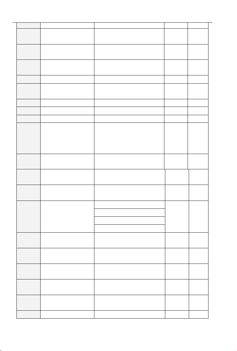
PV series Solar Pumping Inverter
2:Automatic MPPT
H00.03
Vmpp voltage CVT
setting
0~750V
540V
△
H00.04
Mini voltage reference
of MPPT
0~Max Voltage
500V
×
H00.05
Max voltage reference
of MPPT
Max Voltage~750V
600V
×
H00.06
PID Filter Time Given
0.000~10.000s
0.000s
△
H00.07
PID Filter Time
Feedback
0.000~10.000s
0.000s
△
H00.08
PID Filter Time Output
0.000~10.000s
0.000s
△
H00.09
Ratio Gain Kp1
0.00~100.00
0.10
△
H00.10
Points Time KI
0.00~100.00
0.10
△
H00.11
PID Upper Limit of
Output Frequency
PID Lower Limit of Output
Frequency~100.0%(100.0%
corresponds to the max
frequency)
100.0%
×
H00.12
PID Lower Limit of
Output Frequency
0.0%~PID Upper Limit of
Output Frequency
20.0%
×
H00.13
Dormant Delay Time of
Weak light Pre-warning
0.0~6000.0s
600.0s
△
H00.14
Wake-up Delay Time of
Weak Light
0.0~6000.0s
100.0s
△
H00.15
Feedback Channel
Selection of Reservoir
Water Level
0:Null
0
×
1:AI1
2:AI2
3:AI3
H00.16
Clean up the delay time
of full-water pre-warning
0~10000s
600s
△
H00.17
Threshold of reservoir
water level
0.0~100.0
25.0%
△
H00.18
Dormant Delay Time of
Overtank Pre-warning
0~10000s
60s
△
H00.19
Detection of reservoir
hydraulic probe
0.0~100.0
100.0%
△
H00.20
Pre-warning delay time
of pump under-load
0.0~1000.0s
60.0s
△
H00.21
Pre-warning current
0.0~100.0% 0.0:Null
0.0%
△
- 38 -
Page 39
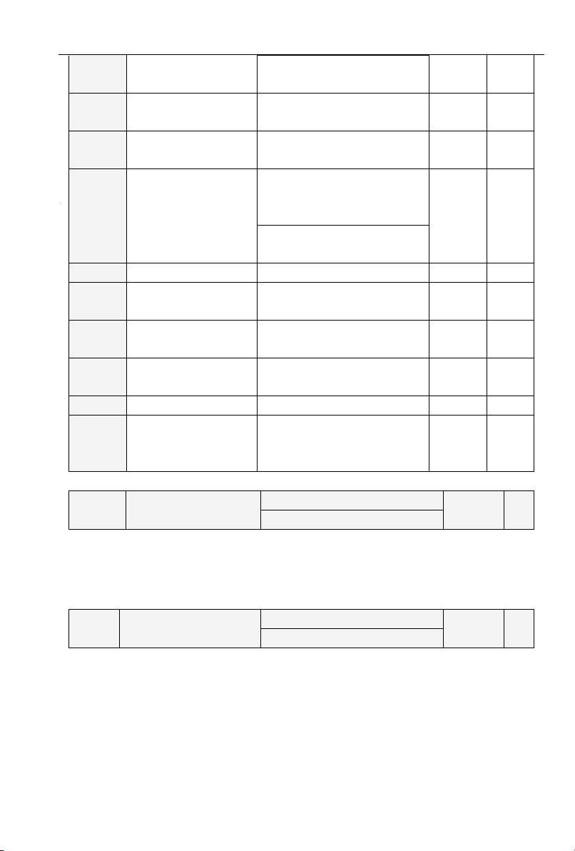
PV series Solar Pumping Inverter
level of pump
under-load
H00.22
Reset delay time of
pump under-load
0.0~1000.0s
60.0s
△
H00.23
Threshold of
lag-frequency
0.00~200.00Hz
0.30Hz
△
H00.24
Water level direction
detection
0:Positive direction,higher
detection value higher water
level
1
×
1:Negative position,higher
detection value lower water level
H00.25
Weak light voltage
250V~MPPT minimum voltage
300V
×
H00.26
Frequency given mode
0: Maximum frequency
1: Master frequency given mode
0 × H00.27
Power automatic switch
function
0:disable
1:Enable
0 × H00.28
Time of automatic
switch to solar power
1~600Min
60Min
△
H00.29
Automatic switch delay
0.1~10.0s
3.0s
△
H00.30
Current power source
in automatic switch
function
0: Grid power
1: Solar power
0
⊙
H00.00
Control of PV Pump
Inverter
0:Null
1
×
1:Valid
H00.01
Selection of inverter power
supply
0:Mains
1
×
1:PV Panels
3.2 H00 Group: Detailed Explanation of Function Code
0:Null
For standard model
1:Valid
For PV pumps special inverter,H00 Group: Invalid
0:Mains
Inverter power supply through the grid, frequency given refer to group of F01, HOO.02~H00.12
invalid.
1:PV Panels
Inverter power supply through solar panels, frequency given mainly through tracking and
adjusting the max power-point PI of solar panels to get. For more details, please refer to H00.02~
H00.12.
- 39 -
Page 40
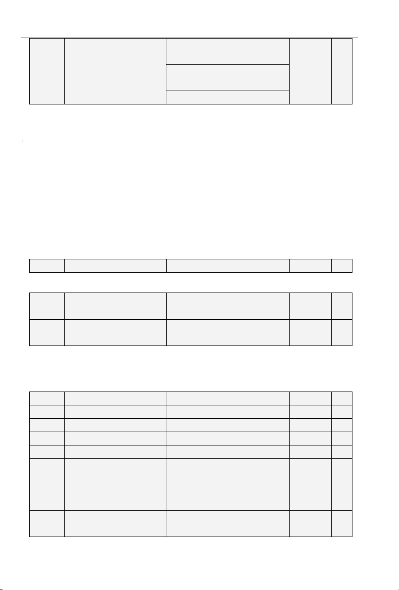
PV series Solar Pumping Inverter
H00.02
Vmpp selection of power
given mode
0:CVT(Constant Voltage appr
Given)
2
×
1:Max Power Point Tracking
(MPPT)
2:Automatic MPPT
H00.03
Vmpp voltage CVT setting
0~750V
540V
△
H00.04
MPPT mini voltage
reference
0~Max Voltage
500V
×
H00.05
MPPT max voltage
reference
Max Voltage~750V
600V
×
H00.06
PID Given Filter Time
0.000~10.000s
0.000s
△
H00.07
PID Response Filter Time
0.000~10.000s
0.000s
△
H00.08
PID Output Filter Time
0.000~10.000s
0.000s
△
H00.09
Ratio Gain Kp1
0.00~100.00
0.10
△
H00.10
Points Time KI
0.00~100.00
0.10
△
H00.11
PID Upper limit of output
frequency
PID Lower limit of output
frequency~100.0%(100.0%
corresponds to the max
frequency)
100.0%
×
H00.12
PID Lower limit of output
frequency
0.0%~PID Upper limit of output
frequency
20.0%
×
0:CVT(Constant Voltage appr Given)
Adopt voltage given mode; reference voltage is a fixed value, given by H00.03.
1:Max power point tracking(MPPT)
Using max power point tracking the given reference voltage, the reference voltage will not stop
changing until the system stable,the maximum power point of this searching mode is limited by range
of H00.04 and H00.05
2:Automatic MPPT
System track the maximum power point automatically, adaptive to different solar panel, can track
and get maximum power point rapidly.
No matter which reference voltage mode adopted, when bus voltage higher than reference
voltage, the target frequency will change to upper limit of PI output frequency; when bus voltage lower
than reference voltage, target frequency will change to lower limit of PI output frequency.
When H00.02 is zero, reference voltage will be given by this function code.
When H00.03 is 1, MPPT voltage will track within H00.04~H00.05, H00.05 must be larger than
H00.04, the smaller the difference between them, the narrower the tracking range, tracking will be
faster. But the voltage point of max power must fall in this range.
- 40 -
Page 41
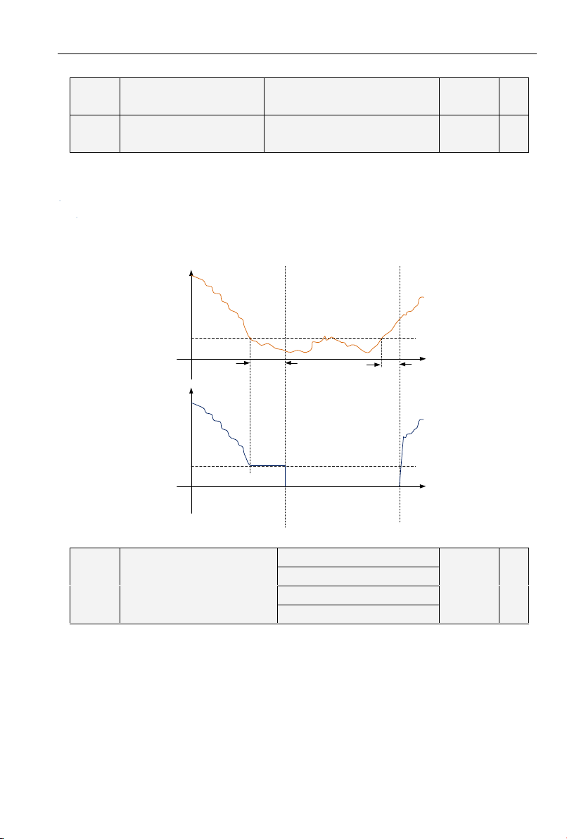
PV series Solar Pumping Inverter
H00.13
Delay time of weak light
pre-warning sleep
0.0~6000.0s
600.0s
△
H00.14
Delay time of weak light
wake-up
0.0~6000.0s
100.0s
△
PI output
Frequency
output
PI lower
limit
Wake up
delay time
of weak
light
Running status Dormancy status
PI lower
limit
Running
status
Dormancy
delay time
of weak
light
H00.15
Feedback channel selection of
reservoir water level
0:Null
0
×
1:AI1
2:AI2
3:AI3
Refer to F13 group of PID function description in FR200 user manual.
When the output frequency less than or equal with the lower limit of PI output frequency (H00.12),
delaying timing begins, continuing this state until delay time of weak light pre-warning (H00.13) arrives,
weak-light pre-warning reported (Arn33), and start dormant.
In weak light pre-warning, when output frequency larger than lower limit of PI output frequency,
delaying timing begins, and continue this status until arrival delay time (H00.14)of wake-up at weak
light, clean the weak light pre-warning, re-enter the running status.
0:Null
Control of water level is invalid.
1:AI1
AI1 for analog signal source of water-level control
2:AI2
AI2 for analog signal source of water-level control
3:AI3
AI3 for analog signal source of water-level control
Figure 3-1 Weak light dormancy & wake up
- 41 -
Page 42
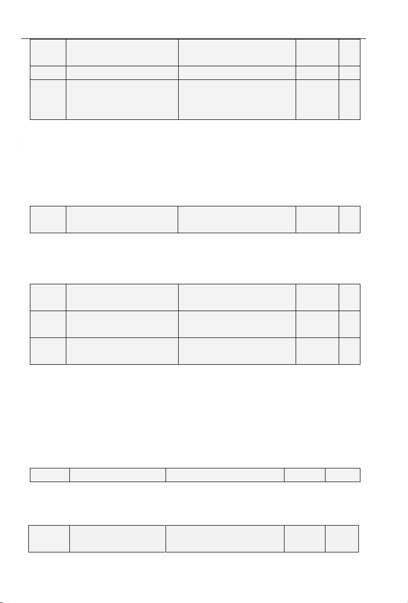
PV series Solar Pumping Inverter
H00.16
Clean up the delay time of
overtank pre-warning
0~10000s
600s
△
H00.17
Reservoir full of water control
0.0~100.0
25.0%
△
H00.18
Dormancy delay time of
reservoir full of water
pre-warning
0~10000s
60s
△
H00.19
Detection of reservoir
hydraulic probe
0.0~100.0
100.0%
△
H00.20
Current level of pump
under-load pre-warning.
0.0~100.0% 0.0: Null
0.0%
△
H00.21
Delay time of pump
under-load pre-warning.
0.0~1000.0s
60.0s
△
H00.22
Delay time of pump
under-load resetting.
0.0~1000.0s
60.0s
△
H00.23
Lag frequency threshold
0.00~200.00Hz
0.30Hz
△
H00.24
Water level direction
detection
0:Positive direction,higher
detection value higher water
1
×
When the detected water level control analog signal less than water level threshold (H00.17), and
continue this status over the delay time of H00.18, reporting the pre-warning of water-full (Arn34), and
dormancy.
In water-full pre-warning, when the detected water level control analog signal larger than H00.17,
delay timer begins, and continue this status over the delay time of H00.16, clear the full-water
pre-warning, recover the normal operation.
0.0% means Null.
When not 0.0%, when the detected water level control analog signal larger than H00.19 hydraulic
probe damaged point, hydraulic probe fault (Err32) will be reported directly, and stopped.
0.0%: Automatically detection of under-load, decided by under-load detection of inverter.
When no 0.0%, decided by H00.20 parameter setting, 100% correspondence to ratted current of
motor.
When absolute value of the difference between target frequency and slop frequency continues
less than or equal with H00.23 lag frequency threshold, if the current value continues less than H00.20
set value, over the H00.21 pump under-load delay time, reporting under-load pre-warning(Arn25).
In under-load pre-warning, delay H00.22 under-load reset time, under-load pre-warning restoration.
Use for adjusting the condition of under-load operation. When absolute value of the difference
between target frequency and slop frequency continues less than or equal with lag frequency
threshold, current comparison will be required.
- 42 -
Page 43
PV series Solar Pumping Inverter
level
1:Negative position,higher
detection value lower water
level
H00.25
Weak light voltage
250V~MPPT minimum voltage
300V
×
H00.26
Frequency given mode
0: Maximum frequency
1: Master frequency given mode
0
×
H00.27
Power automatic switch
function
0:disable
1:Enable
0
×
H00.28
Time of automatic
switch to solar power
1~600Min
60Min
△
H00.29
Automatic switch delay
0.1~10.0s
3.0s
△
H00.30
Current power source
in automatic switch
function
0: Grid power
1: Solar power
0
⊙
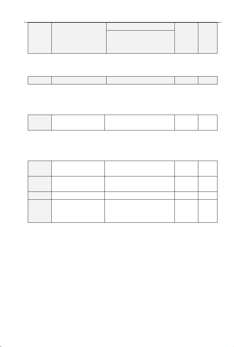
To set the relationship between hydraulic probe detected signal and water level
0: Positive direction, higher detection value higher water level
1: Negative position, higher detection value lower water level
For inverters with 380V, range: 250V~MPPT minimum voltage Default Value:300V
For inverters with 220V, range: 120V~MPPT minimum voltage Default Value:150V
When bus voltage is lower than the value of weak light voltage, inverter will soon entry the statue
of weak light.
0:Maximum frequency
Given frequency is the maximum frequency adjusted by MPPT function
1:Master frequency given mode
In frequency range adjusted by MPPT function, given frequency is adjusted by F01.01
When H00.27=1 power automatic switch function is enable, grid power and solar power will be
switched automatically in system. When system works with grid power, MPPT function is invalid,
speed adjusted by frequency given mode, when running time is over setting time of H00.28, system
will stop and switch to solar power then restart. When system works with solar power, MPPT function
is valid, when system is under weak light, system will stop and switch to grid power than restart. In
every automatic switch, system will stop during the time setting by H00.29 for the switch.
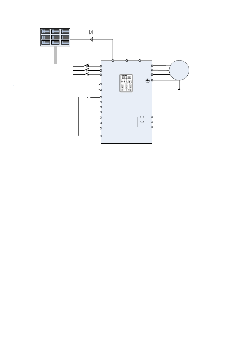
H00.30 shows current power source in automatic switch, wiring as below:
- 43 -
Page 44
PV series Solar Pumping Inverter
+24V
DI1
DI2
DI3
DI4
DI5
DI6
R1A
R1B
R1C
(-) (+) PB
PV200
PLC
DI7/HI
PV panels
KM1
R
S
T
U
V
W
M
COM
Run
KM1
Grid
Figure 3-2Automatic switch between grid and solar power wiring
- 44 -
Page 45
PV series Solar Pumping Inverter
Operator
Panel
Displays
Fault Name
Fault Reasons
Troubleshooting
Err01
Acceleration
Overcurrent
1、Inverter output circuit
grounding or shorted
2、Acceleration time is too
short
3、Manually boost the torque or
V/F curve unsuitable
4、Voltage is too low
5、Start the rotating motor
6、Shock load on acceleration
7、Inverter selection is too
small
1、Peripheral
troubleshooting
2、Prolong the acceleration
time
3、Adjust the V/F curve
Or manually-torque-boost
4、The voltage adjusted to a
normal range
5、Select start on
rotational-speed tracking or
waiting for motor stopped
6、Cancel shock-load
7、Select inverter with a
larger power
Err02
Deceleration
Overcurrent
1、Inverter output circuit
grounding or shorted
2、Deceleration time is too
short
3、Voltage is too low
4、Shock load on deceleration
5、No installation of braking
resistor
1、Peripheral
troubleshooting
2、Prolong the deceleration
time
3、The voltage adjusted to a
normal range
4、Cancel shock-load
5、Install braking resistor
Err03
Constant-speed
Overcurrent
1、Inverter output circuit
grounding or shorted
2、Voltage is too low
3、If there is shock-load during
running
4、Inverter selection is too
1、Peripheral
troubleshooting
2、The voltage adjusted to a
normal range
3、Cancel shock-load
4、Select inverter with a
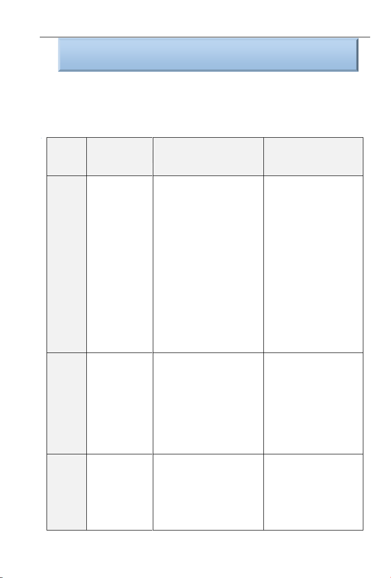
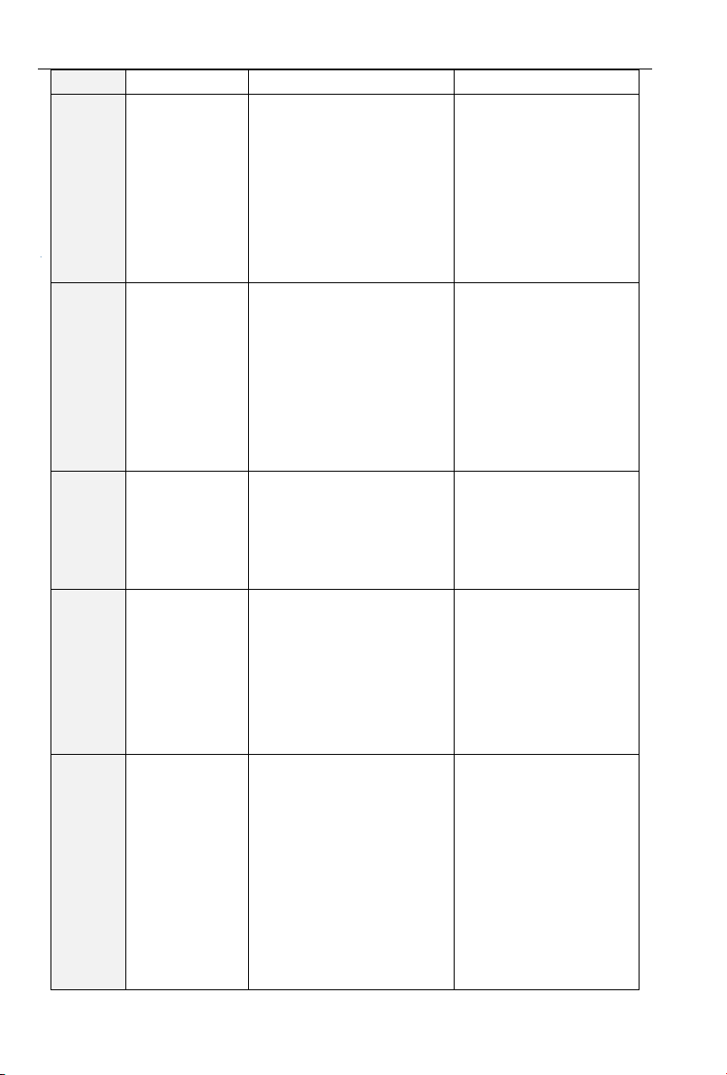
Chapter Four Troubleshooting and Countermeasures
PV200 inverters supply many kinds of warning information and protection functions, when failure
occurred, function of protection actives, inverters will stop output, fault relay contact of inverter active,
and display the fault code on inverter operation panel. Before asking support, users can self-check
according to this chapter tips, and analyze the fault reasons, get the solutions. If fault still can’t be
solved, please ask for service, contact with agents or directly to ADA.
- 45 -
Page 46
PV series Solar Pumping Inverter
small
larger power
Err04
Acceleration
Overvoltage
1、Input voltage is high
2、There is an external force
during acceleration dragging
the motor to work
3、Acceleration time is too
short
4、No installation of braking
resistor
1、The voltage adjusted to a
normal range
2、Cancel the external
power or install braking
resistor
3、Prolong the acceleration
time
4、Install braking resistor
Err05
Deceleration
Overvoltage
1、Input voltage is high
2、There is an external force
during deceleration dragging
the motor to work
3、Deceleration time is too
short
4、No installation of braking
resistor
1、The voltage adjusted to a
normal range
2、Cancel the external
power or install braking
resistor
3、Prolong the deceleration
time
4、Install braking resistor
Err06
Constant-speed
Overvoltage
1、Input voltage is too high
2、There is an external force
during running dragging the
motor to work
1、The voltage adjusted to a
normal range
2、Cancel the external
power or install braking
resistor
Err07
Bus Under
voltage
protection
1、Momentary power failure
2、The inverter input voltage
3、Bus voltage abnormal
4、Rectifier bridge and buffer
resistance are abnormal
5、Drive board abnormal
6、Control panel abnormal
1、Reset Failure
2、Adjust voltage to normal
range
3、Ask for technical support
4、Ask for technical support
5、Ask for technical support
6、Ask for technical support
Err08
Short circuit
protection
shorted
time is too short
3、Wirings between motor and
inverter is too long
4、Module Overheating
5、Internal wirings of inverter
loosened
6、Main Board Abnormal
troubleshooting
2、Prolong the
acceleration/deceleration
time
3、Install the reactor or
output-filter
4、Check and confirm the
air-channel unblocked, fans
operation normal
- 46 -
Page 47
PV series Solar Pumping Inverter
7、Drive Board Abnormal
8、Inverter Module Abnormal
5、All cables plugged
6、Ask for technical support
7、Ask for technical support
8、Ask for technical support
Err09
Input
Open-phase
1、Power of three-phase-input
is abnormal
2、Drive board abnormal
3、Lightning board abnormal
4、Main board abnormal
1、Check and solve the
problems in peripheral
wirings
2、Ask for technical support
3、Ask for technical support
4、Ask for technical support
Err10
Output
Open-phase
1、Lead-wire from inverter to
motor is abnormal
2、Three-phase output of
inverter is unbalanced during
motor-running
3、Drive board abnormal
4、Inverter Module Abnormal
1、Peripheral
troubleshooting
2、Check and confirm the
motor three-phase winding
to be normal
3、Ask for technical support
4、Ask for technical support
Err11
Motor Overload
1、Motor-protection parameters
F11.17 set incorrectly
2、Load is too large or motor
rocked rotor
3、Inverter selection is too
small
1、Setting the parameters
correctly
2、Lowering the load and
check the conditions of
motor and mechanical
3、Select inverter with a
larger power
Err12
Inverter
Overload
1、Load is too large or motor
rocked rotor
2、Inverter selection is too
small
1、Reduce load and check
the conditions of motor and
mechanical
2、Select inverter with a
larger power
Err13
Fault protection
of external input
1、Input the external fault signal
by multi-function terminal
1、Reset to run
Err14
Overheat
1、Ambient temperature is too
high
2、Air-channel blocked
3、Fans damaged
4、Module thermistors
damaged
5、Inverter module damaged
1、Lowering the ambient
temperature
2、Clean up the air-channel
3、Replace the fans
4、Replace the thermistors
5、Replace the inverter
module
Err15
Memory Failure
1、EEPROM Chips damage
1、Replace the Main Board
- 47 -
Page 48
PV series Solar Pumping Inverter
Err16
Cancel the
self-identification
1、Press the button of
STOP/RST during
self-identification
1、Press STOP/RST for
restoration
Err17
Self-identification
failure
1、Motor and the inverter
output terminals are not
connected
2、Motor connects to load
3、Motor Failure
1、Check the wirings
between inverter and motor
2、Motor breaks away from
load
3、Check motor
Err18
485
Communication
Timeout
1、Upper computer works
abnormally
2、Communication cable is
abnormal
3、F15 communication
parameters set incorrectly
1、Check the wirings of
upper computer
2、Check the
communication cable
3、Set the communication
parameters correctly
Err19
PID feedback
disconnection on
running
1、PID feedback lower than the
value set by F13.24
1、Check the PID feedback
signal or set F13.24 to be a
suitable value
Err20
The running time
arrives
1、Setting the function of
running time arrives
1、Refer to description of
F05.14
Err21
Parameter
Upload Error
1、Copy card uninstalled or
plugged unsuitable
2、Parameters copy card
abnormal
3、Control board abnormal
1、Parameter copy card
installed correctly
2、Ask for technical support
3、Ask for technical support
Err22
Parameter
Download Error
plugged unsuitable
2、Parameters copy card
abnormal
3、Control board abnormal
1、Parameter copy card
installed correctly
2、Ask for technical support
3、Ask for technical support
Err23
Braking Unit
failure
1、Braking wirings fault or
braking tube damaged
2、Value of external braking
resister is too small
1.Check the brake unit, and
replace the new brake tube
2.Increasing the braking
resistor
Err24
Disconnection
Fault of
temperature
sensor
1、Temperature sensor failure
or cable break
1、Ask for technical support
Err25
Inverter
loss-load
1、Running current of inverter
is less than F11.22
1、Confirm whether the load
loss or parameters of
- 48 -
Page 49
PV series Solar Pumping Inverter
F11.22、F11.23 conform
to the actual running
conditions.
Err26
With-wave
current limit fault
1、Load is too large or motor
rocked-rotor
2、Inverter selection is too
small
1、Reduce the load or
check the conditions of
motor or mechanical
2、Select the inverter with
larger power
Err27
Soft-start relay
unclosed
Err28
EEPROM
Version
Incompatible
1、Parameter version of
up/download module is
inconsistent with the one of
control panel
1、Re-upload parameters to
up/download modules
Err29
Hardware detect
Overcurrent
1、Acceleration/Deceleration
time is too short
2、Motor Parameters is
Inaccurate
3、Hardware failure of
Inverter
1、Prolong the
acceleration/deceleration
time
2、Setting the correct motor
parameter
3、Ask for technical support
Err30
Hardware detect
overvoltage
1、Deceleration time is too
short
2、No installation of braking
resistors
3、Hardware failure of
Inverter
1、Prolong the deceleration
time
2、Install the braking
resistor
3、Ask for technical support
Err32
Hydraulic Probe
Failure
Hydraulic Probe Failure
Hydraulic Probe Changed
Arn33
Pre-warning of
Weak Light
Output frequency lower than or
equal with lower limit of PI
output frequency, and
continues this status until
arrives at delay time of weak
light.
Check the lower limit of PI
output frequency
and weak-light delay
the set value
Arn34
Pre-warning of
Full-water
Water-lever feedback lower
than the set threshold, and
continue to the delay time
Check the pre-warning
point of water level
- 49 -
 Loading...