

Page 1

FR200H Special Purpose Inverters for Multi-pumps Constant Pressure Water Supply
- 1 -
Preface
FR200H series is a enhanced type during all FRECON inverters group, special design for
HVAC, air conditioner and water-supply industry, use for fan, pumps and other loads, support 2
modes water supply of fixed variable-frequency pump and cycle variable-frequency pumps, flexible
control logic of add/reduce pumps, dormancy/awaken based on pressure, timing rotate control and
other special functions.
When debugging the product, please refer to debugging guide in the user manual. Product
maintenance please refers to FR200 user manual.
IMPORTANT NOTES
◆To illustrate the details of the products,pictures in this manual based on products with outer
casing or safety cover being removed.When using this product, please be sure to well install
outer casing or covering by the rules, and operating in accordance with the manual contents.
◆The illustrations this manual for illustration only and may vary with different products you have
ordered.
◆The company is committed to continuous improvement of products, product features will
continue to upgrade, and the information provided is subject to change without notice.
◆If you are using have questions; please contact our regional agents or our customer service
center. Customer Service Tel 0755 -33067999.
◆The company's other products please visit our website: http://www.frecon.com.cn
Page 2

FR200H Special Purpose Inverters for Multi-pumps Constant Pressure Water Supply
- 2 -
Contents
Preface ........................................................................................................................................ - 1 -
Contents ...................................................................................................................................... - 2 -
Chapter 1 Product Information ................................................................................................... - 3 -
1.1 Nameplate information ....................................................................................................... - 3 -
1.2 Information of FR200H Product Model ................................................................................ - 4 -
1.3 Terminal Configuration ........................................................................................................ - 4 -
1.4 Configuration, Mounting Dimensions and Weight ................................................................ - 8 -
Chapter 2 Debugging Guide ..................................................................................................... - 10 -
Chapter 3 List of Parameters .................................................................................................... - 11 -
3.1 Standard Function Parameters ......................................................................................... - 11 -
Chapter 4 Maintenance and troubleshooting .......................................................................... - 27 -
Page 3

FR200H Special Purpose Inverters for Multi-pumps Constant Pressure Water Supply
- 3 -
Chapter 1 Product Information
1.1 Nameplate information
Fig.1-1 Nameplate information
Model Explanation
Model show on product nameplate contains information below
FR200 H-4T-7.5G/011P B
Product series code:
FR200H
Input voltage:
2: 220V(-15%~+30%)
4: 380V(-15%~+30%)
Input voltage phases:
S:Single-phase
T:Three-phase
Industry-specific series
code H: special use for
multi-pumps constant
pressure water supply
Brake unit:
None: No Braking Unit
B: Built-in brake unit(30kW
following built,37 ~ 75kW optional
built,No built above 90kW)
Adaptable Motor (kW)And Type of
Motor:7.5G:7.5kW(General type)
011P:11kW(Fan pump type)
Figure 1-2 Product Model Number Naming Rule
Page 4

FR200H Special Purpose Inverters for Multi-pumps Constant Pressure Water Supply
- 4 -
1.2 Information of FR200H Product Model
Table 1-1FR200HProduct model and technical data
Model No.
Power
capacity
KVA
Rated
Input current
A
Rated output
current
A
Applicable motor
kW HP
3-Phase: 380V,50/60Hz Range: -15%~+30%
FR200H-4T-0.7G/1.5PB
1.5
3.4
2.5
0.75
1
FR200H-4T-1.5G/2.2PB
3
5.0
4.2
1.5
2
FR200H-4T-2.2GB
4
5.8
5.5
2.2
3
FR200H-4T-4.0G/5.5PB
6
11
9.5
3.7、4
5
FR200H-4T-5.5G/7.5PB
8.9
14.6
13
5.5
7.5
FR200H-4T-7.5G/011PB
11
20.5
17
7.5
10
FR200H-4T-011G/015PB
17
26
25
11
15
FR200H-4T-015G/018PB
21
35
32
15
20
FR200H-4T-018G/022PB
24
38.5
37
18.5
25
FR200H-4T-022G/030PB
30
46.5
45
22
30
FR200H-4T-030G/037PB
40
62
60
30
40
FR200H-4T-037G/045P
57
76
75
37
50
FR200H-4T-037G/045PB
FR200H-4T-045G/055P
69
92
91
45
60
FR200H-4T-045G/055PB
FR200H-4T-055G/075P
85
113
112
55
70
FR200H-4T-055G/075PB
FR200H-4T-075G/090P
114
157
150
75
100
FR200H-4T-075G/090PB
FR200H-4T-090G/110P
134
160*
176
90
125
FR200H-4T-110G/132P
160
190*
210
110
150
FR200H-4T-132G/160P
192
232*
253
132
175
FR200H-4T-160G/185P
231
282*
304
160
210
FR200H-4T-185G/200P
240
326*
350
185
250
FR200H-4T-200G/220P
250
352*
377
200
260
FR200H-4T-220G/250P
280
385*
426
220
300
FR200H-4T-250G/280P
355
437*
470
250
330
FR200H-4T-280G/315P
396
491*
520
280
370
FR200H-4T-315G/355P
445
580*
600
315
420
FR200H-4T-355G/400P
500
624*
650
355
470
FR200H-4T-400G/450P
565
690*
725
400
530
FR200H-4T-450G/500P
623
765*
800
450
600
1.3 Terminal Configuration
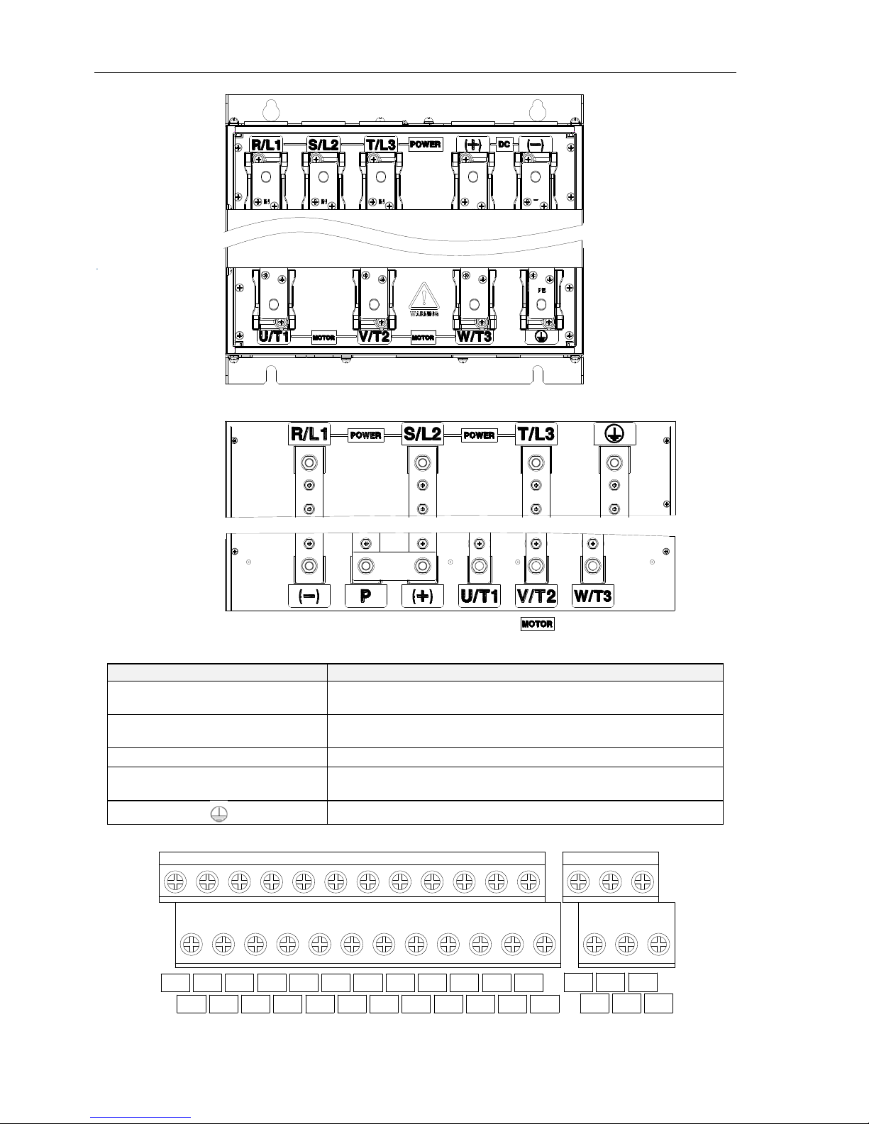
1.3.1 Main Circuit Terminals
a: 1.5~2.2kWMain Circuit Terminals
(+)
(-)
R
S
T
U
V
POWER
Control circuit
terminals
Main circuit
terminals
Upload and
download interfaces
Fig.1-3 1.5~2.2kW Schematic of main circuit terminals
Page 5

FR200H Special Purpose Inverters for Multi-pumps Constant Pressure Water Supply
- 5 -
b:4~18.5kW Main Circuit Terminals
Control circuit
terminals
Main circuit
terminals
Upload and
download interfaces
PB
(+)
(-)
RFI
Fig.1-4 4.0~18.5kW Schematic of main circuit terminals
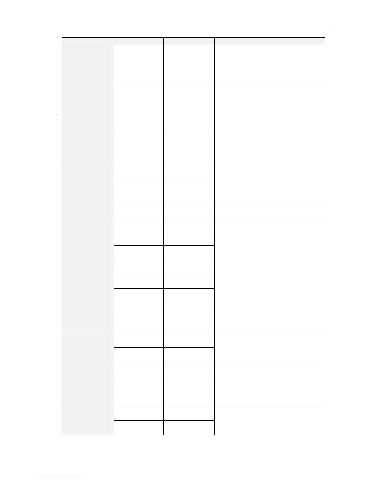
c: 22~30kW Main Circuit Terminals
Solution 1:
Fig.1-5 22~37kW Main Circuit Terminals(Solution 1)Schematic
Solution 2:
Fig.1-6 22~37kW Main Circuit Terminals(Solution 2)Schematic
d: 45~90kW Main Circuit Terminals
Fig.1-7 45~90kW Main Circuit TerminalsSchematic
Page 6
FR200H Special Purpose Inverters for Multi-pumps Constant Pressure Water Supply
- 6 -
e: 110~315kW Main Circuit TerminalsSchematic
Fig.1-8 110~315kW Main Circuit TerminalsSchematic
f:355-400kW Main Circuit Terminals
Fig.1-9 355~400kW Main Circuit TerminalsSchematic
Table 1-2 main circuit terminal functions
Terminal marks
Functions
R/L1、S/L2、T/L3
AC power input terminals for connecting to 3-phase AC380V
power supply.
U/T1、V/T2、W/T3
AC output terminals of inverter for connecting to 3-phase
induction motor.
(+)、(-)
Positive and negative terminals of internal DC bus.
B
Connecting terminals of braking resistor. One end connected
to + and the other to B.
Grounding terminal
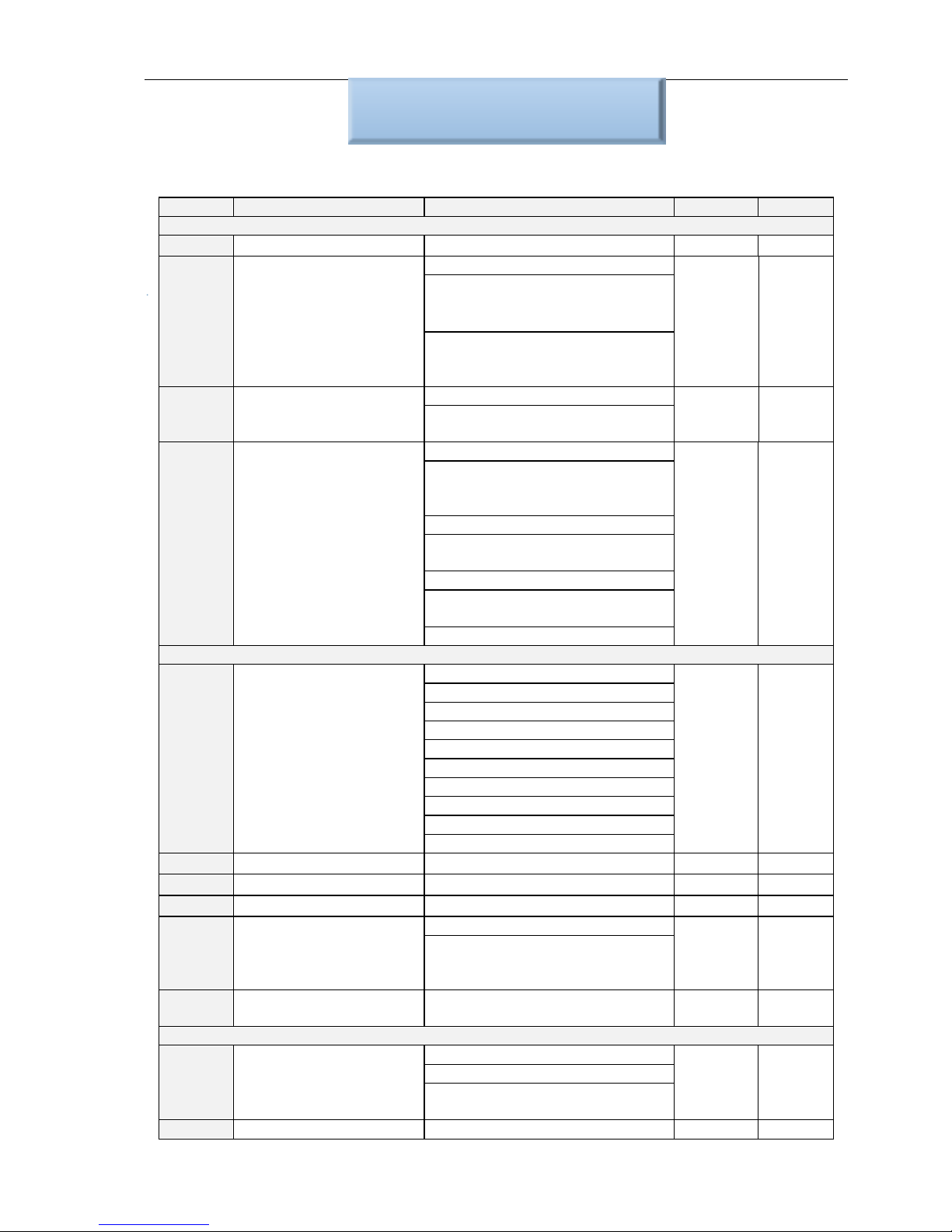
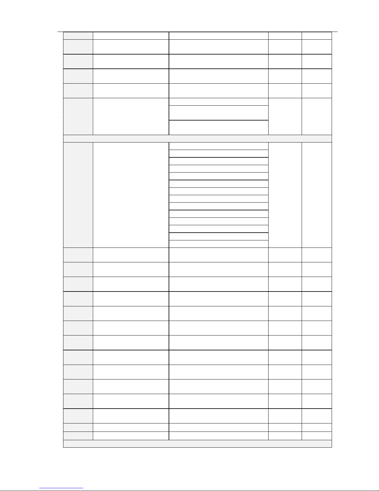
2.3.2 Control circuit terminals
Fig. 1-10 control circuit terminalsschematic
DI1
+24V
DI2
PLC
DI3
COM
DI4
DI5
COM
DI6
Y1
Y2
+10V
R1A R1B
R1C
R2A R2B
R2C
AO1
AI1
GND
AI2
485+
AI3
485-
PE
DI7/HI
AO2
GND
Page 7
FR200H Special Purpose Inverters for Multi-pumps Constant Pressure Water Supply
- 7 -
Table 1-3 FR200H Description of control circuit terminals
Type
Terminal
Name
Function Description
Power supply
+10V-GND
External +10 V
power supply
Provide +10 V power supply to
external unit.
Generally, it provides power supply to
externalpotentiometer with resistance
range of 1–5 kΩ.
Maximum output current: 10 mA
+24V-COM
External +24V
power
supply Applying
to Overvoltage
Category II
circuit
Provide +24 V power supply to
external unit.
Generally, it provides power supply to
DI/Do terminals and external sensors.
Maximum output current: 200 mA
PLC
Input terminal
of
external power
supply
Connect to +24 V by default.
When DI1-DI7 need to be driven by
externalsignal, PLC needs to be
connected to externalpower supply
and be disconnected from +24 V.
Analog input
AI1-GND
Analog input 1
Input voltage range: DC 0~10V/0~
20mA,decided by toggle switches
AI1、AI2 on the control board
Impedance: 250 kΩ (voltage input),
250 Ω (current input)
AI2-GND
Analog input 2
AI3-GND
Analog input 3
Input Voltage Range: DC -10~+10V
Input impedance: 250kΩ
Switch input
DI1- COM
Switch input
terminals 1
Maximum input frequency: 200Hz
Impedance: 2.4kΩ
Voltage range for level input: 9V~
30V
DI2- COM
Switch input
terminals 2
DI3- COM
Switch input
terminals 3
DI4- COM
Switch input
terminals 4
DI5- COM
Switch input
terminals 5
DI6- COM
Switch input
terminals 6
DI7/HI-COM
Switch input
terminals 7 OR
High-speed
pulse input
Besides features of DI1–DI6, it can be
used for high-speed pulse input.
Maximum input frequency: 100 kHz
Analog
output
AO1-GND
Analog output
terminal 1
Output voltage range: DC 0~10V/0~
20mA,decided by toggle switches
AO1、AO2 on the control board
Impedance requirements≥10kΩ
AO2-GND
Analog output
terminal 2
Switch output
Y1-COM
Open collector
output 1
Voltage range: 0~24V
Current range: 0~50mA
Y2/HO-COM
Open collector
output 2 OR
High-speed
pulse output
Besides features of Y1, it can be used
forHigh-speed pulse output channels.
The maximum output frequency:
100kHz
Relay output
R1A-R1C
Normally open
terminal
Contact driving capacity:
AC250V,3A,COSØ=0.4.
DC 30V,1A
R1B-R1C
Normally
closedterminal
Page 8

FR200H Special Purpose Inverters for Multi-pumps Constant Pressure Water Supply
- 8 -
R2A-R2C
Normally open
terminal
R2B-R2C
Normally
closedterminal
485
Communication
485+-485-
485
Communication
Terminals
Rate:
4800/9600/19200/38400/57600/
115200bps
Termination resistor is set by the
toggle switch on the control panel
RS485
GND
485
Communication
shielded
ground
Shield
PE
Shield Ground
Ground terminal for shield
Auxiliary
Interface
External
operation
panel interface
Use standard network cable
Maximum cable distance: 50m
UP/DOWNLOAD
Parameter
copy interface
1.4 Configuration, Mounting Dimensions and Weight
a:1.5~18.5kW Dimensions and wall mounting dimensions
Fig. 1-11 1.5~18.5kW Wall installation diagram
b: 22~400kW Dimensions and wall mounting dimensions
Fig.1-12 22~160kW Wall installation diagram (1) Fig. 1-13185~400kW Wall installation diagram (2)
W1
H1
H
W
D
4Xd
W1
W
H1
H
D
4xd
H
W
D
H1
d W1 W1
Page 9

FR200H Special Purpose Inverters for Multi-pumps Constant Pressure Water Supply
- 9 -
Table 1-4 Configuration, mounting dimensions and weight
Model NO.
External and installation dimensions(mm)
Weight
(Kg)
W
W1 H H1
D
Mounting
Hole
Diameter
3-Phase: 380V,50/60Hz Range: -15%~+30%
FR200H-4T-0.7G/1.5PB
117
107
187
177
160
4.5
1.9
FR200H-4T-1.5G/2.2PB
FR200H-4T-2.2GB
FR200H-4T-4.0G/5.5PB
146
131
249
236
177
5.5
3.2
FR200H-4T-5.5G/7.5PB
FR200H-4T-7.5G/011PB
FR200H-4T-011G/015PB
198
183
300
287
185
5.5
5.4
FR200H-4T-015G/018PB
FR200H-4T-018G/022PB
255
176
459
443
220 7 15.5
FR200H-4T-022G/030PB
FR200H-4T-030G/037PB
FR200H-4T-037G/045P
270
130
590
572
260 7 27.5
FR200H-4T-045G/055P
FR200H-4T-055G/075P
357
230
590
572
260 7 37
FR200H-4T-075G/090P
FR200H-4T-090G/110P
430
320
830
802
293
12
77.7
FR200H-4T-110G/132P
FR200H-4T-132G/160P
FR200H-4T-160G/185P
500
180
1107
1078
328
14
138.5
FR200H-4T-185G/200P
FR200H-4T-200G/220P
FR200H-4T-220G/250P
660
230
1160
1130
340
14
190
FR200H-4T-250G/280P
FR200H-4T-280G/315P
FR200H-4T-315G/355P
810
300
1140*
1110
400
14
196
FR200H-4T-355G/400P
FR200H-4T-400G/450P
* Note: 1. 110~315kw optional base height is 263mm.
2. 355~400kw dc reactor can be installed in a trench or cabinet independently, if the vertical installation,
need to purchase base (dc reactor can be installed in the base), base height is 400 mm.
Page 10

FR200H Special Purpose Inverters for Multi-pumps Constant Pressure Water Supply
- 10 -
Chapter 2 Debugging Guide
FR200H series special purpose inverter for multi-pumps constant pressure water supply specially
developed for constant pressure water supply industry, featured with 2 modes below:
Mode 1: fixed variable frequency control mode wirings:
DI1
DI2
DI3
DI4
DI6
COM
FR200H
DI5
Q3
Q4
Default Signal
Q2
10V
AI1
AI2
GND
Given
Feedback
FWD
REV
Q5
DI7
R1A
R1C
R2A
R2C
KA1
KA2
Y1
Y2
24V
M1
M2
M3
M4
M5
L1
L2
L3
220V
KM2
KM3
KM4
KM5
R1A
R1C
R2A
R2C
KA1
KA2
R
S
T
U
V
W
Inside the dotted line is powerfrequency pumps, can be added on
customers’ requirements up to 4 pcs
Fig. 2-1 Fixed Pumps Mode Wirings
Mode 2: two variable frequency pumps cycle control mode wirings:
DI1
DI2
DI3
DI4
DI6
COM
FR200H
DI5
Q3
Q4
Default Value
Q2
10V
AI1
AI2
GND
Given
Feedback
FWD
REV
Q5
DI7
R1A
R1C
R2A
R2C
KA1
KA2
Y1
Y2
24V
M1
L1
L2
L3
M2
KM1
KM2
KM3
KM4
U
V
W
R
S
T
220V
KM1
KM2
KM3
KM4
R1A
R1C
R2A
R2C
KA1
KA2
Fig. 2-2 two variable frequency cycle mode wirings
Page 11
FR200H Special Purpose Inverters for Multi-pumps Constant Pressure Water Supply
- 11 -
Chapter 3 List of Parameters
3.1 Standard Function Parameters
Table 3-1 Standard Function Parameters
Param.
Parameter Name
Instructions
Default
Attr
Group F00: System Parameters
F00.00
User Password
0~65535
0
×
F00.01
Display of Parameters
0: Display all parameters
0
×
1: Only display F00.00, F00.01
and user-defined parameters
F17.00~F17.29
2: Only display F00.00, F00.01,
and the parameters different with
factory default
F00.03
G/P type display
0: G type (constant torque load)
1
×
1: P type (variable torque load
e.g. fan and pump)
F00.04
Parameter Initialization
0: Invalid
0
×
1: Restore all parameters to
factory default (excluding motor
parameters)
2: Clear fault record
3: Restore user backup
parameters
4: Back up user parameters
5: Restore factory default(include
motor parameters)
6: Clear power dissipation
Group F01: Frequency Command
F01.01
Master Frequency
Command Source
0: Master digital setting (F01.02)
6
×
1: keypad potentiometer
2: Analog input AI1
3: Communication
4: Multi-reference
5: PLC
6: Process PID output
7: DI7/HI pulse input
8: Analog input AI2
9: Analog input AI3
F01.08
Maximum frequency
20.00~600.00Hz
50.00Hz
×
F01.09
Upper limit frequency
Fdown~Fmax
50.00Hz
×
F01.10
Lower limit frequency
0.00~Fu
0.00Hz
×
F01.11
Operation when
command frequency
lower than lower limit
frequency
0: Run at lower limit frequency
0
×
1: Run at 0 Hz would be
activated after the time delay set
by F01.12
F01.12
Lower limit frequency
running time
0.0~6000.0s
60.0s
×
Group F02: Start/Stop Control
F02.00
Run command
0: Keypad control (LED off)
1
×
1: Terminal control (LED on)
2: Communication control (LED
blinking)
F02.12
Stop mode
0: Ramp to stop
0
Page 12

FR200H Special Purpose Inverters for Multi-pumps Constant Pressure Water Supply
- 12 -
1: Coast to stop
F02.20
0Hz output selection
0:No-voltage output
0
×
1:Voltage output
Group F03: Accel/Decel Parameters
F03.00
Accel time 1
0.0~6000.0s
15s
△
F03.01
Decel time 1
0.0~6000.0s
15s
△
Group F04 Digital Input
F04.00
Function of terminal DI1
00: No function
01: Running forward (FWD)
02: Running reverse (REV)
03: Three-wire running control
04: JOG forward (FJOG)
05: JOG reverse (RJOG)
06: Coast to stop
07: Fault reset (RESET)
08: Running pause
09: External fault input
10: Terminal Up
11: Terminal DOWN
12: UP/DOWN (including ∧/∨
key) adjustment clear
13: Multi-step frequency terminal
1
14: Multi-step frequency terminal
2
15: Multi-step frequency terminal
3
16: Multi-step frequency terminal
4
17: Accel/Decel time determinant
1
18: Accel/Decel time determinant
2
19: Accel/Decel disabled(ramp
stop not inclusive)
20: Given frequency switching as
the auxiliary frequency source
21: PLC status reset
22: Simple PLC paused
23: ID paused
24: PID adjustment direction
25: PID integration paused
26: PID parameter switch
27: Swing frequency
pause(output the
currentfrequency)
28: Swing frequency reset(output
the central frequency)
29: Run command switched to
keypad control
30: Run command switched to
terminal control
31: Run command switched to
communication control
32: Count input
33: Count clear
34: Length pulse input
35: Length clear
1
×
F04.01
Function of terminal DI2
2
×
F04.02
Function of terminal DI3
7
×
F04.03
Function of terminal DI4
13
×
F04.04
Function of terminal DI5
0
×
F04.05
Function of terminal DI6
0
×
F04.06
Function of terminal DI7
0
×
Page 13

FR200H Special Purpose Inverters for Multi-pumps Constant Pressure Water Supply
- 13 -
36: DC brake input command at
stop
37:Speed/Torque control switch
38: Disable reverse
39: Disable forward
50: Special purpose inverter
enable
51: No.1 pump status
52: No.2 pump status
53: No.3 pump status
54: No.4 pump status
55: No.5 pump status
F04.13
Terminal DI1~DI5
positive/negative logic
DI5、DI4、DI3、DI2、DI1
00000
0: Positive logic(Terminals are on
at 0V/off at 24V)
1: Negative Logic (Terminals are
off at 0V/on at 24V)
F04.14
Terminal DI6~AI3
positive/negative logic
AI3、AI2、AI1、DI7、DI6
00000
0: Positive logic
1: Negative Logic
Group F05 Digital Output
F05.00
Y1 output function
00: No output
01: Drive is running
02: Fault output
03: Frequency-level detection
(FDT1)
04: Frequency-level detection
(FDT2)
05: Drive in 0Hz running 1 (no
output at stop)
06: Drive in 0Hz running 2(output
at stop)
07: Upper limit frequency
attained
08: Lower limit frequency
attained
09: Frequency attained
10: Inverter is ready to work
11: Drive (motor) overloaded
alarm
12: Inverter overheat warning
13: Current running time attained
14: Accumulative power-on time
attained
15: Consecutive running time
attained
16: PLC cycle completed
17: Set count value attained
18: Designated count value
attained
19: Length attained
20: Under-load warning
21: Brake output
22: DI1
23: DI2
30: No.1 pump power-frequency
control terminal
31: No.2 pump power-frequency
1
×
F05.01
Y2 output function
3
×
F05.02
Relay 1 output function
2
×
F05.03
Relay 2 output function
11
×
Page 14

FR200H Special Purpose Inverters for Multi-pumps Constant Pressure Water Supply
- 14 -
control terminal
32: No.3 pump power-frequency
control terminal
33: No.4 pump power-frequency
control terminal
34: No.5 pump power-frequency
control terminal
35: No.1 pump
variable-frequency control
terminal
36: No.2 pump
variable-frequency control
terminal
F05.08
Enabled state of digital
output
Unit: Y1
0000
0: Positive Logic
1: Negative Logic
Decade: Y2 (same as unit)
Hundreds place: Relay 1 output
(same asunit)
Thousands place: Relay 2 output
(same as unit)
Group F07 Analog and Pulse Output
F07.00
AO1 output function
00: No output
1
×
F07.01
AO2 output function
01: Output frequency
2
×
F07.02
Y2/HO output function
(when used as HO)
02: Command frequency
1
×
03: Output current (rated current)
04: Output voltage(rated voltage)
05: Output power
06: Bus voltage
07: +10V
08: keypad potentiometer
09: AI1
10: AI2
11: AI3
12: HI (100% to 10.00kHz)
13: Output torque (torque
absolute value)
Group F08 Parameters of Motor 1
F08.01
Rated power of motor 1
0.10~600.00kW
Model
defined
×
F08.02
Rated voltage of motor 1
60~660V
Model
defined
×
F08.03
Rated current of motor 1
0.1~1500.0A
Model
defined
×
F08.04
Rated frequency of
motor 1
20.00~Fmax
Model
defined
×
F08.05
Rated speed of motor 1
1~30000
Model
defined
×
F08.07
The rated power factor
of async motor 1
0.50~0.99
Model
defined
×
F08.08
Stator resistance R1 of
async motor 1
0.001~65.535Ω
Model
defined
×
F08.09
Rotor resistance R2 of
async motor 1
0.001~65.535Ω
Model
defined
×
F08.10
Leakage inductance L1
of async motor 1
0.001~65.535mH
Model
defined
×
F08.11
Mutual inductance L2 of
0.1~6553.5mH
Model
×
Page 15
FR200H Special Purpose Inverters for Multi-pumps Constant Pressure Water Supply
- 15 -
asynchronous motor 1
defined
F08.12
No-load current of
async motor 1
0.1~1500.0A
Model
defined
×
F08.13
Field weakening coeff 1
of async motor 1
0.0~100.0
87%
×
F08.14
Field weakening coeff 2
of async motor 1
0.0~100.0
75%
×
F08.15
Field weakening coeff 3
of async motor 1
0.0~100.0
70%
×
F08.30
Autotuning of motor 1
0: No autotuning
0
×
1: Static autotuning of async
motor
2: Rotary autotuning of async
motor
Group F09 V/f Control Parameters of Motor 1
F09.00
V/f curve setting
00: LinearV/F
3
×
01: Multi-stage V/F
02: 1.2nd power V/F
03: 1.4th power V/F
04: 1.6th power V/F
05: 1.8th power V/F
06: 2.0nd power V/F
07: V/F complete separation
08: V/F half separation
09: 1.2 power inverse curve V/F
10: 1.4 power inverse curve V/F
11: 1.6 power inverse curve V/F
12: 1.8 power inverse curve V/F
13: 2.0 power inverse curve V/F
F09.01
Torque boost
0.0%–30.0% 0.0% (fixed
torque boost)
0.0%
△
F09.02
Cut-off frequency of
torque boost
0.00~Fmax
50.00Hz
△
F09.03
Multi-point V/F
frequency 1(F1)
0.00~F09.05
0.00Hz
△
F09.04
Multi-point V/F voltage 1
(V1)
0.0~100.0
0.0%
△
F09.05
Multi-point V/F
frequency 2(F2)
F09.03~F09.05
5.00Hz
△
F09.06
Multi-point V/F voltage 2
(V2)
0.0~100.0
14.0%
△
F09.07
Multi-point V/F
frequency 3(F3)
F09.05~F09.09
25.00Hz
△
F09.08
Multi-point V/F voltage 3
(V3)
0.0~100.0
50.0%
△
F09.09
Multi-point V/F
frequency 4(F4)
F09.07~rated motor frequency
50.00Hz
△
F09.10
Multi-point V/F voltage 4
(V4)
0.0~100.0 Ue=100.0%
100.0%
△
F09.11
V/F slip compensation
gain
0.0~300.0%
80.0%
△
F09.12
Stator voltagedrop
compensation gain
0.0~200.0%
100.0%
△
F09.13
Excitation boost gain
0.0~200.0%
100.0%
△
F09.14
Oscillation Suppression
0.0~300.0%
100.0%
△
Group F11 Protection Parameters
Page 16

FR200H Special Purpose Inverters for Multi-pumps Constant Pressure Water Supply
- 16 -
F11.00
Current limit control
0: Current limit disabled
2
×
1: Current limit mode 1
2: Current limit mode 2
F11.01
Current limit
100.0~200.0%
150.0%
×
F11.02
Frequency decreasing
time(limit current in
constant speed
operation)
0.0~6000.0s
5.0s
△
F11.03
Current limit mode 2
proportion gain
0.1~100.0%
3.0%
△
F11.04
Current limit mode 2
integral time
0.00~10.00 s (0.00: integral
is invalid)
10.00s
△
F11.05
Overvoltage Stall
Control
0: Overvoltage stall disabled
1
×
1: Overvoltage stall mode 1
2: Overvoltage stall mode 2
F11.06
Overvoltage Stall
Voltage
600~800V(380V inverter)
320~400V(220V inverter)
730V
370V
×
F11.07
Overvoltage Stall
Mode 2 Proportion Gain
0.1~100.0%
50.0%
△
F11.08
Overvoltage Stall
Mode 2 frequency
limited
0.00~50.00Hz
5.00Hz
△
F11.10
Protection action 1
Unit's place: Bus undervoltage
03330
×
0: Fault reported and coast to
stop
1: Stop according to the stop
mode
2: Fault reported but continue
torun
3: Fault protection disabled
Ten's digit :Power input phase
Loss (Err09)(Same as unit's
place )
Hundred's digit :Power output
phase loss(Err10)(Same as unit's
place )
Thousand's digit:Motor
overload(Err11)(Same as unit's
place )
Ten thousand's digit:Inverter
overload(Err12)(Same as unit's
place )
F11.11
Protection action 2
External equipment fault(Err13)
00000
×
0: Fault reported and coast to
stop
1: Stop according to the stop
mode
2: Fault reported but continue
torun
Ten's digit: EEPROM read/write
fault (Err15) (Same as unit's
place)
Hundred's digit: Communication
overtime error (Err18) (Same as
unit's place)
Thousand's digit: PID feedback
Page 17

FR200H Special Purpose Inverters for Multi-pumps Constant Pressure Water Supply
- 17 -
loss (Err19) (Same as unit's
place)
Ten thousand's digit: Continuous
running time reached (Err20)
(Same as unit's place)
F11.12
Protection action 3
Unit's place: Module temperature
detection disconnection(Err24)
00030
×
0: Fault reported and coast to
stop
1: Stop according to the stop
mode
2: Fault reported but continue to
run
Ten's digit: Load becoming 0
(Err25) (Same as unit's place)
Hundred's digit:reserved
thousand's digit:reserved
Ten thousand's digit:reserved
F11.14
Frequency selection for
continuing to run upon
fault
0: Current running frequency
1
×
1: Set frequency
2: Frequency upper limit
3: Frequency lower limit
4: Backup frequency upon
abnormality
F11.15
Backup frequency upon
abnormality
0.00~Fmax
0.00Hz
×
F11.17
Motor overload
protection time
30.0~300.0s
60.0s
×
F11.18
Overload alarm
Unit's place: detection option:
000
×
0: Always detect
1: Detect at constant speed only
Ten's digit :compared object
0: Rated current of motor
1: Rated current of drive
Hundred’s digit:report error or not
0:Do not report
1:Report
F11.19
Overload alarm
threshold
20.0~200.0%
130.0%
×
F11.20
Overload alarm
activated time that
exceeding threshold
0.1~60.0s
5.0s
×
F11.21
Inverter overheat
warning threshold
50~overheatTemperature
Model
defined
×
F11.22
Detection level of power
loss
5.0~100.0%
20.0%
×
F11.23
Detection time of power
loss
0.1~60.0s
5.0s
×
F11.24
Action selection at
instantaneous power
failure
0: Disabled
0
×
1: Enabled
F11.25
Decel time at
instantaneous power
failure
0.0~6000.0s
5.0s
△
F11.26
Rapid current limit
0: Disabled
0
×
1: Enabled
F11.27
Times of automatic
0~20
0
×
Page 18
FR200H Special Purpose Inverters for Multi-pumps Constant Pressure Water Supply
- 18 -
reset
F11.28
Interval of automatic
reset
0.1~100.0s
1.0s
×
F11.29
DO action during fault
auto reset
0: Not act
0
×
1: Act
F11.30
Instant Power-failure
Bus Voltage
60.0%~Recovery Voltage
80%
F11.31
Instant Power-failure
Recovery Voltage
Power Failure Voltage~100.0%
85%
F11.32
Instant Power-failure
Voltage Adjustment
Time
0.01~10.00s
0.1
F11.33
Instant Power-failure
Gain K
0.1~100.0%
40.0%
F11.34
Instant Power-failure
Integral Time Ti
0.00~10.00s (0.00: Integral
Invalid)
0.1
Group F13 Process PID
F13.00
PID setting
0: F13.01 digital setting
2
×
1: keypad potentiometer
2: AI1
3: Communication
4: Multi-Reference
5: DI7/HI pulse input
6: AI2
7: AI3
F13.01
PID digital setting
0.0~100.0%
50.0%
△
F13.02
PID feedback
0: AI1
1
×
1: AI2
2: Communication
3: AI1+AI2
4: AI1-AI2
5: Max{AI1,AI2}
6: Min{AI1,AI2}
7: DI7/HI pulse input
8: AI3
F13.03
PID setting
feedbackrange
0~6000.0
100.0
△
F13.04
PID action direction
0: Forward action
0
×
1: Reverse action
F13.05
Filtering time of PID
setting
0.000~10.000s
0.000s
△
F13.06
Filtering time of PID
feedback
0.000~10.000s
0.000s
△
F13.07
Filtering time of PID
output
0.000~10.000s
0.000s
△
F13.08
Proportional gain Kp1
0.0~100.0
1.0
△
F13.09
Integration time Ti1
0.01~10.00s
0.10s
△
F13.10
Differential time Td1
0.000~10.000s
0.000s
△
F13.11
Proportional gain Kp2
0.0~100.0
1.0
△
F13.12
Integration time Ti2
0.01~10.00s
0.10s
△
F13.13
Differential time Td2
0.000~10.000s
0.000s
△
F13.14
PID setting
feedbackrange
0: No switch, determined by
parameters Kp1, Ti1 and Td1
0
×
1: Auto switch on the basis of
input offset
Page 19

FR200H Special Purpose Inverters for Multi-pumps Constant Pressure Water Supply
- 19 -
2: Switched by terminal
F13.15
PID parameter
switchover
deviation 1
0.0~100.0%
20.0%
×
F13.16
PID parameter
switchover
deviation 2
0.0~100.0%
80.0%
×
F13.17
PID offset limit
0.0~100.0%
0.0%
×
F13.18
PID integral property
Unit's digit (Whether to stop
integral operation when the
output reaches the limit)
00
×
0: Continue integral operation
1: Stop integral operation
Ten's digit (Integral separated)
0: Invalid
1: Valid
F13.19
PID differential limit
0.0~100.0%
0.5%
×
F13.20
PID initial value
0.0~100.0%
0.0%
×
F13.21
Holding time of PID
initial value
0.0~6000.0s
0.0s
×
F13.22
PID output frequency
upper limit
PID output frequency lower
limit~100.0%(100.0%
corresponds to maximum
frequency )
100.0%
×
F13.23
PID output frequency
lower limit
–100.0%~PID output frequency
upper limit
0.0%
×
F13.24
Detection value of
PID feedback loss
0.0~100.0%
0.0%: Not judging feedback loss
0.0%
×
F13.25
Detection time of
PID feedback loss
0.0~30.0s
1.0s
×
F13.26
PID operation at stop
Uinit’s digit:PID operation
0: No PID operation at stop
1: PID operation at stop
000
×
Ten’s digit:Output limit
0: Do not limit
1: limit
Hundred’s digit:PID digital given
by UP/DOWN
0: Clear to zero when power off
1: Preserve whenpower off
F13.27
UP/DOWN speed of PID
digital given
0.0~100% (0.0% valid)
0.0%
△
Group F14: Swing Frequency, Fixed Length ,Wakeup and Count
F14.10
Wakeup frequency
Dormant frequency (F14.12)~
Fmax
0.00Hz
△
F14.11
Wakeup delay time
0.0~6000.0s
0.0s
△
F14.12
Dormant frequency
0.00~Wakeup frequency
0.00Hz
△
F14.13
Dormant delay time
0.0~6000.0s
0.0s
△
F14.14
Wakeup Mode Selection
0: frequency wakeup
0
×
1: pressure wakeup
F14.15
Dormant Mode
Selection
0: frequency dormant
0
×
1: pressure dormant
F14.16
Pressure Feedback
Source
0: AI1
0
×
1: AI2
2: DI7/HI Pulse Input
Page 20

FR200H Special Purpose Inverters for Multi-pumps Constant Pressure Water Supply
- 20 -
3: AI3
F14.17
Wakeup Pressure
0.0%~Dormant Pressure
10.0%
△
F14.18
Dormant Pressure
Wakeup Pressure~100.0%
50.0%
△
Group U00 Status Monitoring
U00.00
Running frequency
0.00~Fu
0.00Hz
⊙
U00.01
Set frequency
0.00~Fmax
0.00Hz
⊙
U00.02
Output voltage
0~660V
0.0V
⊙
U00.03
Output current
0.0~3000.0A
0.0A
⊙
U00.04
Output power
-3000.0~3000.0kW
0.0kW
⊙
U00.05
Estimated Motor
Speed
0~60000rm
0rm
⊙
U00.06
Bus voltage
0~1200V
0V
⊙
U00.07
Synchronous Frequency
0.00~Fu
0.00Hz
⊙
U00.08
PLC step
1~15
1
⊙
U00.09
Program Operation
Time
0.0~6000.0s(h)
0.0s(h)
⊙
U00.10
PID set
0~60000
0
⊙
U00.11
PID feedback
0~60000
0
⊙
U00.12
Status of DI1~DI5
digital input terminal
DI5 DI4 DI3 DI2 DI1
00000
⊙
U00.13
Status of DI6~DI7
digital input terminal
DI7 DI6
00
⊙
U00.14
Status of digital output
terminal
R2 R1 Y2 Y1
0000
⊙
U00.15
AI1 input
0.0~100.0%
0.0%
⊙
U00.16
AI2 input
0.0~100.0%
0.0%
⊙
U00.17
AI3 input
-100.0~100.0%
0.0%
⊙
U00.18
Keypad potentiometer
input
0.0~100.0%
0.0%
⊙
U00.19
HI input
0.00~100.00kHz
0.00kHz
⊙
U00.20
AO1 output
0.0~100.0%
0.0%
⊙
U00.21
AO2 output
0.0~100.0%
0.0%
⊙
U00.22
HO output
0.00~100.00kHz
0.00kHz
⊙
U00.23
Temperature of inverter
-40.0℃~120.0℃
0.0℃
⊙
U00.24
Accumulative power-on
time
0~65535min
0min
⊙
U00.25
Accumulative running
time
0~6553.5min
0.0min
⊙
U00.26
Cumulative power-on
time
0~65535h
0h
⊙
U00.27
Cumulative running time
0~65535h
0h
⊙
U00.28
Count value
0~65535
0
⊙
U00.29
Length value
0~65535m
0m
⊙
U00.30
Linear speed
0~65535m/min
0m/Min
U00.31
Output torque
0.0~300.0%
0.0%
⊙
U00.32
Motor temperature by
PTC
-40℃~200℃
0℃
⊙
U00.33
Speed detected by
encoder
0~60000rpm
0rpm
⊙
U00.34
Encoder lines
0~65535
0
⊙
U00.35
Power dissipation
0~65535kWh
0kWh
⊙
U00.36
VDI1~VDI5 input state
VDI5 VDI4 VDI3 VDI2 VDI1
00000
⊙
Page 21

FR200H Special Purpose Inverters for Multi-pumps Constant Pressure Water Supply
- 21 -
U00.37
VDO1~VDO5 output
state
VDO5 VDO4 VDO3 VDO2 VDO1
00000
⊙
Group U01 Fault Record
U01.00
Current Fault Type
Err00: No fault
0
⊙
Err01: Accel overcurrent
Err02: Decel overcurrent
Err03: Constant-speed
overcurrent
Err04: Accel overvoltage
Err05: Decel overvoltage
Err06: Constant-speed
overvoltage
Err07: Bus undervoltage
Err08: Short circuit
Err09: Power input phase loss
Err10: Power output phase loss
Err11: Motor overload
Err12: Inverter overload
Err13: External equipment fault
Err14: Module overheat
Err15: EEPROM read/write fault
Err16: Motor auto-tuning
cancelled
Err17: Motor auto-tuning fault
Err18: Communication overtime
error
Err19: PID feedback loss
Err20: Continuous running time
reached
Err21: Parameter upload fault
Err22: Parameter download
fault
Err23: Braking unit fault
Err24: Module temperature
detection disconnection
Err25: Load becoming 0
Err26: With-wave current limit
fault
Err27: Inverter soft-start relay is
off
Err28: Software
versioncompatibility fault
Err29: Instantaneous
overcurrent
Err30: Instantaneous
overvoltage
U01.01
Running frequency
when the latest fault
occurred
0.00~Fu
0.00Hz
⊙
U01.02
Output current when the
latest fault occurred
0.0~3000.0A
0.0A
⊙
U01.03
Bus voltage when the
latest fault occurred
0~1200V
0V
⊙
U01.04
Cumulative running time
when the latest fault
occurred
0~65535h
0h
⊙
Page 22

FR200H Special Purpose Inverters for Multi-pumps Constant Pressure Water Supply
- 22 -
U01.05
Code of previous fault
Same as U01.00
0
⊙
U01.06
Running frequency
when previous fault
occurred
0.00~Fu
0.00Hz
⊙
U01.07
Output current when
previous fault occurred
0.0~3000.0A
0.0A
⊙
U01.08
Bus voltage when
previous fault occurred
0~1200V
0V
⊙
U01.09
Cumulative running time
when previous fault
occurred
0~65535h
0h
⊙
U01.10
Before-previous fault
code
Same as U01.00
0
⊙
U01.11
Running frequency
when before-previous
fault occurred
0.00~Fu
0.00Hz
⊙
U01.12
Output current when
before-previous fault
occurred
0.0~3000.0A
0.0A
⊙
U01.13
Bus voltage when
before-previous fault
occurred
0~1200V
0V
⊙
U01.14
Cumulative running time
when before-previous
fault occurred
0~65535h
0h
⊙
H00 group: multi-pumps constant pressure water supply
H00.00
Special purpose
inverter function enable
0: Invalid
0
×
1: Valid
H00.01
Work modes selection
0: fixed variable-frequency
pumps mode
1: 2 variable-frequency pumps
cycle mode
0
×
H00.02
Frequency for add
pumps
Frequency for reduce
pumps~max frequency
50.00Hz
△
H00.03
Frequency for reduce
pumps
0.00Hz~frequency for add
pumps
5.00Hz
△
H00.04
Pressure tolerance for
add pumps
0.0~100.0%
0.0%
△
H00.05
Pressure tolerance for
reduce pumps
0.0~100.0%
0.0%
△
H00.06
Added pumps delay
0.0~300.0s
20.0s
△
H00.07
Reduced pumps delay
0.0~300.0s
15.0s
△
H00.08
Time for added pumps
speed arrival max
0.0~300.0s
1.0s
△
H00.09
Time for reduced
pumps zero-flow
0.0~300.0s
1.0s
△
H00.10
Switching time
0.1~10.0s
1.0s
×
H00.11
Pumps Status
Unit: No.1 pump status
0:Spare
1:Enable
Decade: No.2 pump status(same
with unit)
Hundreds: No.3 pump
status(same with unit)
Kilobit: No.4 pump status(same
with unit)
00011
△
Page 23

FR200H Special Purpose Inverters for Multi-pumps Constant Pressure Water Supply
- 23 -
Myriabit: No.5 pump status(same
with unit)
H00.12
Timing rotate or not
0:fixed order
1:start first stop first
2:timing rotate
0
×
H00.13
Gap of timing rotate
1~60000Min
240Min
×
H00.14
Inverter action selection
when adding or
reducing pump in
single-variable pump
mode
0:Inverter stop
0
×
1:Inverter not stop
3.2 H00 group function code detailed explanation
H00.00
Special purpose
inverters function enable
0: Invalid
0
×
1: Valid
0: Invalid
Standard type
1: Valid
Special purpose type for multi-pumps constant water supply, H00 group parameters valid
H00.01
Work mode selection
0: Fixed variable-frequency
pump mode
0
×
1: 2 variable-frequency pumps
cycle mode
0: Fixed variable-frequency pump mode
Inverter 3-phase output control a certain pump as fixed variable-frequency pump, other pumps
power-frequency run/stop controlled by programmable D0 output. (max control 1*fixed
variable-frequency pump+4*power-frequency pumps), power-frequency pump conform to “start first
stop first”. Under this mode, 4*power-frequency pumps corresponding to No.2~5 pumps, according to
the specific site situation requirements for the numbers of power-frequency pumps, which can be
achieved by set multi-functions input (51~54) and H00.11, for more details please refer to H00.11
instructions. Wirings refer to Figure 3-1.
DI1
DI2
DI3
DI4
DI6
COM
FR200H
DI5
Q3
Q4
Default Value
Q2
RST
M4
M3
M2
M1
10V
AI1
AI2
GND
Given
Feedback
U
V
W
KM1
KM2
KM3
FWD
REV
Q5
DI7
R1A
R1C
R2A
R2C
220V
KM1
KM2
KM3
KM4
R1A
R1C
R2A
R2C
KA1
KA2
3-phase power supply
24V
PLC
KA1
KA2
Y1
Y2
24V
M5
KM4
Figure 3-1 Fixed Variable-frequency Pumps Mode Wirings
Page 24

FR200H Special Purpose Inverters for Multi-pumps Constant Pressure Water Supply
- 24 -
Fixed variable-frequency pumps mode parameters setting instructions
F01.01=6 (PID preset)
F02.00=1 (external terminals)
F04.02=9(external default
input)
F05.00=31(No.2
power-frequency pump)
F05.01=32 (No.3
power-frequency pump)
F05.02=33(No.4
power-frequency pump)
F05.03=34(No.5
power-frequency pump)
F13.00=2 (AI1 Pressure
Preset)
F13.02=1AI2(Pressure
Feedback)
H00.01=0(single-variable
pump, multi-power
frequency pump)
H00.11=1111(all pumps start)
Note: in case of using 2 pumps or 3 pumps, set parameter (H00.11 pump status) corresponding to set
the un-usage pump to be 0, the pump stops.
1: 2 variable-frequency pumps cycle mode
Water supply system doesn’t fix a certain pump as variable-frequency pump, when system pressure is
insufficient, the running variable-frequency pump firstly switch to grid-power frequency running, and
then variable-frequency enable the next new pump, the pump is the new variable-frequency pump.
When the system has too much pressure, power-frequency pump stops. The same moment at most
only one pump work as variable-frequency pump, another one work on power-frequency, (can control
2*variable-frequency pumps work in cycle). Wirings refer to Figure 3-2.
DI1
DI2
DI3
DI4
COM
DI5
Q2
Default Value
Q1
R
S
T
M1
10V
AI1
AI2
GND
Given
Feedbac
k
U
V
W
KM1
FWD
REV
R1A
R1C
R2A
R2C
220V
KM1
KM2
KM3
KM4
R1A
R1C
R2A
R2C
KA1
KA2
3-phase power supply
24V
PLC
M2
KM2
KM3
KM4
KA1
KA2
Y1
Y2
24V
FR200H
Figure 3-2 2 variable-frequency pumps cycle mode
2 variable-frequency pumps cycle modeparameters setting instructions:
F01.01=6(ID preset)
F02.00=1(External terminals)
F04.02=9(External default
input)
F05.00=36(No.2
variable-frequency pump)
F05.01=31(No.2
power-frequency pump)
F05.02=35(No.1
variable-frequency pump)
F05.03=30(No.1
power-frequency pump)
F13.00=2(AI1 pressure
preset)
F13.02=1 (AI2 pressure
feedback)
H00.01=1(multi-variable
pumps)
H00.11=0011(all pumps start)
Note: when set parameter (H00.11 pump status) of corresponding unused pump to be zero (spare),
the pump stops.
H00.02
Frequency for add
pumps
Frequency for reduce
pumps~max frequency
50.00Hz
△
H00.03
Frequency for reduce
0.00Hz~frequency for add
5.00Hz
△
Page 25

FR200H Special Purpose Inverters for Multi-pumps Constant Pressure Water Supply
- 25 -
pumps
pumps
H00.04
Pressure tolerance for
add pumps
0.0~100.0%
0.0%
△
H00.05
Pressure tolerance for
reduce pumps
0.0~100.0%
0.0%
△
H00.06
Added pumps delay
0.0~300.0s
20.0s
△
H00.07
Reduced pumps delay
0.0~300.0s
15.0s
△
Add pumps: running frequency≥H00.02 set value, feedback pressure<set pressure-pressure
tolerance, and last the delay time set by H00.06, meet the terms of add pumps, add pump.
Reduce pumps: running frequency≤H00.03 set value, feedback pressure>set pressure+pressure
tolerance, and last the delay time set by H00.07, meet the terms of reduce pumps, reduce pump.
H00.08
Time for added pumps
speed arrival max
0.0~300.0s
1.0s
△
H00.09
Time for reduced pumps
zero-flow
0.0~300.0s
1.0s
△
Time for added pumps speed arrival max: when command for adding pumps being sent, a
delay(H00.08 parameters) been start, which makes the pump arrive at its rated speedbefore start
another pump(avoid shaking).
Time for reduced pumps zero-flow: when command for adding pumps being sent, a delay(H00.09
parameters) been start, which makes the pump can stop effectively before stop another pump(avoid
shaking).
H00.10
Switching time
0.1~10.0s
1.0s
×
This function mainly use for protection inverter and AC power supply from short-circuited, which
caused by contactor action delay when a motor switched from variable frequency to power frequency.
Set the shortest time larger than the total of relay action time and contactor action time, generally
the contactor action from connect to disconnect takes longer time than switch from disconnect to
connect, please operate on longer time.
H00.11
Pump status
Unit: No.1 pump status
0:spare
1:start
Decades: No.2 pump status
(same with unit)
Hundreds: No.3 pump status
(same with unit)
Thousands: No.4 pump
status(same with unit)
Myriabit: No.5 pump
status(same with unit)
00011
△
Spare: Control terminals DI1~DI7 are multi-functional terminals, which define their functions by
setting the value of F04.00~F04.03. Repeat definition is allowed, one of the re-defined
terminals valid, the function valid. 51~54 is special functions for constant pressure water
supply, instructions as below: 51~54:No.1~No.4 pumps status.
Start: When function of DI1~DI7 terminal defined as 51~54, terminals valid, then the corresponding
pumps allowed to run, if terminals invalid, and F04.00~F04.03 corresponding pumps status
selected to be 1: start, then the pumps allowed to run, if selected to be 0: spare, then the
pumps not allowed to run.
H00.12
Timing rotate or not
0:fixed order
1:start first stop first
2:timing rotate
0
×
0: fixed order: start the pumps from small to large.
1: start first stop first: firstly start the running time shortest one when add pumps, firstly stop the
running time longest one when reduce pumps.
2: timing rotate:(1)Single variable pump, with assisted pump switched, timing rotate. When 2 pcs or
more than 2 pcs assisted pumps running at the same time, if system meets the term of reduce
pumps, the firstly started pump will stop first; if the one of them keep running more than H00.13
(timing rotate gap), the assisted pump stops, and start the pump with longest stop time. (2) Multi
Page 26

FR200H Special Purpose Inverters for Multi-pumps Constant Pressure Water Supply
- 26 -
variable pump, with assisted pump, with timing rotate. Start current variable pump, when the
running frequency higher than frequency for add pumps, start H00.06 delay, if the frequency
still higher than frequency for add pumps after the delay, then start the other assisted pump.
When variable pump keep running within a certain time, no need to start assisted pumps, if the
time ,more than timing rotate time set by H00.12, then stop the current variable pump, switch
the assisted pump to variable pump.
H00.13
Gap of timing rotate
1~60000Min
240Min
×
Single variable mode: when parts of power-frequency motor running, water supply system under
stable, to avoid parts of motor keep running in a long time, timing rotate time set for limit the longest
running time.
Multi variable mode: when only variable pumps running, and keep running time more than set timing
rotate time, then stop the current running pump and switch to another variable pump.
H00.14
Inverter action selection
when adding or reducing
pump in single-variable
pump mode
0: Inverter stop
0
×
1: Inverter not stop
0:Inverter stop
In single-varialble pump mode, when adding or reducing pump , inverter will stop.
1: inverter not stop
In single-varialble pump mode, when adding or reducing pump , inverter will not stop.
Page 27

FR200H Special Purpose Inverters for Multi-pumps Constant Pressure Water Supply
- 27 -
Chapter 4 Maintenance and troubleshooting
FR200H inverter provides a number of warning information and protection, when a fault occurs,
the protective function is activated, the inverter will stop output, inverter fault relay contact, and in the
inverter displays the fault code on the display panel. Before seeking service user can press the
self-examination tips in this section, analyze problems, and identify solutions. If the problem still
cannot be excluded, seek services, or contact the dealer you purchase the driver with my company.
Display
Fault Name
Possible Causes
Solutions
Err01
Accel overcurrent
1: The output circuit is
grounded or short circuited.
2: The acceleration time is too
short.
3: Manual torque boost or V/F
curve is not appropriate.
4: The voltage is too low.
5: The startup operation is
performed on the rotating
motor.
6: A sudden load is added
during acceleration.
7: The AC drive model is of too
small power class.
1: Eliminate external faults.
2: Increase the acceleration
time.
3: Adjust the manual torque
boost or V/F curve.
4: Adjust the voltage to
normal range.
5: Select rotational speed
tracking restart or start the
motor after it stops.
6: Remove the added load.
7: Select an AC drive of
higher power class
Err02
Decel overcurrent
1: The output circuit is
grounded or short circuited.
2: The deceleration time is too
short.
3: The voltage is too low.
4: A sudden load is added
during deceleration.
5: The braking unit and
braking resistor are not
installed.
1: Eliminate external faults.
2: Increase the deceleration
time.
3: Adjust the voltage to
normal range.
4: Remove the added load.
5: Install the braking unit and
braking resistor.
Err03
Constant-speed
overcurrent
1: The output circuit is
grounded or short circuited.
2: The voltage is too low.
3: A sudden load is added
during operation.
4: The AC drive model is of too
small power class.
1: Eliminate external faults
2: Adjust the voltage to
normal range.
3: Remove the added load
4: Select an AC drive of
higher power class.
Err04
Accel overvoltage
1: The input voltage is too
high.
2: An external force drives the
motor during acceleration.
3: The acceleration time is too
short.
1: Adjust the voltage to
normal range.
2: Cancel the external force
or install a braking resistor.
3: Increase the acceleration
time.
Page 28

FR200H Special Purpose Inverters for Multi-pumps Constant Pressure Water Supply
- 28 -
4: The braking unit and
braking resistor are not
installed.
4: Install the braking unit and
braking resistor.
Err05
Decel
overvoltage
1: The input voltage is too
high.
2: An external force drives the
motor during deceleration.
3: The deceleration time is too
short.
4: The braking unit and
braking resistor are not
installed.
1: Adjust the voltage to
normal range.
2: Cancel the external force
or install the braking resistor.
3: Increase the deceleration
time.
4: Install the braking unit and
braking resistor.
Err06
Constant-speed
overvoltage
1: The input voltage is too high
2: An external force drives the
motor during deceleration.
1: Adjust the voltage to
normal range.
2: Cancel the external force
or install the braking resistor.
Err07
Bus undervoltage
1: Instantaneous power failure
occurs on the input power
supply.
2: The AC drive's input voltage
is not within the allowable
range.
3: The bus voltage is
abnormal.
4: The rectifier bridge and
buffer resistor are faulty.
5: The drive board is faulty.
6: The main control board is
faulty.
1: Reset the fault.
2: Adjust the voltage to
normal range.
3: Contact the agent or
Frecon.
Err08
Short circuit
1: The output circuit is
grounded or short circuited.
2: The connecting cable of the
motor is too long.
3: The module overheats.
4: The internal connections
become loose.
5:The main control board is
faulty
6: The drive board is faulty.
7: The inverter module is
faulty.
1: Eliminate external faults.
2: Install a reactor or an
output filter.
3: Check the air filter and the
cooling fan.
4: Connect all cables
properly.
5: Contact the agent or
Frecon.
Err09
Power input
phase loss
1: The three-phase power
input is abnormal.
2: The drive board is faulty.
3: The lightening board is
faulty.
4: The main control board is
faulty.
1: Eliminate external faults.
2: Contact the agent or
FRECON.
Page 29

FR200H Special Purpose Inverters for Multi-pumps Constant Pressure Water Supply
- 29 -
Err10
Power output
phase loss
1: The cable connecting the
AC drive and the motor is
faulty.
2: The AC drive's three-phase
outputs are unbalanced when
the motor is running.
3: The drive board is faulty.
4: The module is faulty.
1: Eliminate external faults.
2: Check whether the motor
Three-phase winding is
normal.
3: Contact the agent or
Frecon.
Err11
Motor overload
1: F11-17 is set improperly.
2: The load is too heavy or
locked-rotor occurs on the
motor.
3: The AC drive model is of too
small power class.
1: Set F11-17 correctly.
2: Reduce the load and
check the motor and the
mechanical condition.
3: Select an AC drive of
higher power class.
Err12
Inverter overload
1: The load is too heavy or
locked-rotor occurs on the
motor.
2: The AC drive model is of too
small power class.
1: Reduce the load and
check the motor and
mechanical condition.
2: Select an AC drive of
higher power class.
Err13
External
equipment fault
1: External fault signal is input
via DI.
Reset the operation.
Err14
Module overheat
1: The ambient temperature is
too high.
2: The air filter is blocked.
3: The fan is damaged.
4: The thermally sensitive
resistor of the module is
damaged.
5: The inverter module is
damaged.
1: Lower the ambient
temperature.
2: Clean the air filter.
3: Replace the damaged
fan.
4: Replace the damaged
thermally sensitive resistor.
5: Replace the inverter
module.
Err15
EEPROM
read/write fault
The EEPROM chip is
damaged.
Replace the main control
board.
Err16
Motor auto-tuning
cancelled
Since the identification
process, press STOP / RST
key
Press STOP / RST key to
reset
Err17
Motor auto-tuning
fault
1: the motor and the inverter
output terminals are not
connected
2: The motor does not
disengage the load
3: The electrical fault
1: check the connection
between the inverter and
motor
2: The motor is disengaged
load
3: Check the motor
Err18
Communication
overtime
error
1: The PC is not working
properly
2: The communication line is
not normal
3: F15 set communication
parameters set incorrectly
1: Check the PC Connection
2: Check the communication
cable
3: The communication
parameters are set correctly
Err19
PID feedback
loss
PID feedback set value is less
than F13.24
Check the PID feedback
signal or set to an
appropriate value F13.24
Page 30

FR200H Special Purpose Inverters for Multi-pumps Constant Pressure Water Supply
- 30 -
Err20
Continuous
running time
reached
Set the running time to reach
this function
reference F05.14
Description
Err21
Parameter upload
fault
1: Is not installed or is not
plugged parameter copy card
2: Parameter copy card
anomalies
3: The control board
abnormalities
1: a copy of the card is
properly installed
parameters
2: for technical support
3: for technical support
Err22
Parameter
download fault
1: Is not installed or is not
plugged parameter copy card
2: Parameter copy card
anomalies
3: The control board
abnormalities
1: A copy of the card is
properly installed
parameters
2: For technical support
3: For technical support
Err23
Braking unit fault
1: The brake line failure or
damage the brake pipe
2: An external braking resistor
is too small
1: Check the brake unit,
replace the brake pipe
2: Increasing the braking
resistor
Err24
Module
temperature
detection
disconnection
The temperature sensor
failure or cable break
For technical support
Err25
Load becoming0
The AC drive running current
is lower than F11.22
Check that the load is
disconnected or the setting
F11-22 and F11-23 is
correct.
Err26
With-wave
current limit fault
1: The load is too heavy or
locked rotor occurs on the
motor.
2: The AC drive model is of too
small power class.
1: Reduce the load and
check the motor and
mechanical condition.
2: Select an AC drive of
higher power class.
Err27
Inverter soft-start
relay is off
1: The grid voltage is too low
2: Rectifier module failure
1: Check the grid voltage
2: Demand for technical
support
Err28
Software version
compatibility fault
1: The upper and lower
transmission module
parameters in the parameter
version of the control panel
version mismatch.
re-upload module
parameters to pass down
Err29
Instantaneous
overcurrent
1. Inverter output circuit being
grounded or short-circuit;
2. The acceleration and
deceleration time is too short;
3. Manually torque boost or
V/F curve not appropriate;
4. Voltage too low;
5. Start the running motor;
6. Sudden-load in the acce
process;
1. Troubleshooting
peripheral problems;
2. To increase the
acceleration time;
3. Adjust the manually
torque boost or V/F curve;
4. Adjust the voltage to
normal range;
5. Select RPM track start or
start after motor stopped;
Page 31

FR200H Special Purpose Inverters for Multi-pumps Constant Pressure Water Supply
- 31 -
7. Model selection of inverter
power is too small.
6. Cancel sudden-load;
7. Select the inverter with
larger power.
Err30
Instantaneous
overvoltage
1: Input voltage is too high;
2. There is external force drag
the motor to run in dece
process;
3. The deceleration time is too
short;
4.No installation of braking
resistor.
1: Adjust the voltage to
normal range;
2. Cancel external force or
install brake resistor;
3. To increase the
deceleration time;
4.Install braking resistor
Err40
Set running time
finished
1. Cumulative running time
(U00.27) no less than using
time (F00.25)
1. Contact distributors
Page 32

FR200H Special Purpose Inverters for Multi-pumps Constant Pressure Water Supply
- 32 -
 Loading...