

FRC Turbofoam TFC100, Turbofoam TFC200, Turbofoam TFC300, Turbofoam TFC400 User Manual

TFC100 Rev180215
Document Number:
XE-TFC1PM-R0A
DIRECT INJECTION
FOAM PROPORTIONING SYSTEM
WITH ELECTRIC FOAM CONCENTRATE PUMP
MODELS: TFC100, TFC200, TFC300, TFC400
TFC100
TFC200
TFC300
TFC400
FIRE RESEARCH CORPORATION
www.reresearch.com
26 Southern Blvd., Nesconset, NY 11767
TEL 631.724.8888 FAX 631.360.9727 TOLL FREE 1.800.645.0074
1

TFC100 Rev180215
CONTENTS
Table of Contents
CONTENTS .......................................................................................................................................2
INTRODUCTION .............................................................................................................................5
Overview .....................................................................................................................................................................5
Features .......................................................................................................................................................................6
Specications ..............................................................................................................................................................7
GENERAL DESCRIPTION ..............................................................................................................9
Components ................................................................................................................................................................9
General System Layout .............................................................................................................................................11
Controls and Indicators .............................................................................................................................................13
OPERATION AND PROGRAMMING ....................................................................................... 15
OPERATION ...................................................................................................................................16
Detailed Information .................................................................................................................................................16
Operation Notes ........................................................................................................................................................18
Switching Foam Tanks - Automatic Flush (TFC400 Only) ......................................................................................18
Manual Mode ............................................................................................................................................................18
Error Codes and Fault Warnings ...............................................................................................................................19
Preset Settings ...........................................................................................................................................................20
PROGRAMMING ........................................................................................................................... 21
Enter Password for Program Access .........................................................................................................................21
Operator P100 Codes ................................................................................................................................................23
Set Date and Time .....................................................................................................................................................25
Set Discharge Flow Sensor ID Names (TFC200/300/400) ......................................................................................26
Set +/– Increment Value ............................................................................................................................................27
Restore Programmed Functions ................................................................................................................................28
CALIBRATION, MAINTENANCE, AND TROUBLESHOOTING ........................................ 29
CALIBRATION ............................................................................................................................... 30
Calibrate Discharge Flow Sensor (Password Code 1111) ........................................................................................31
Calibrate Foam Concentrate Pump (Password Code 1112) ......................................................................................32
MAINTENANCE RECOMMENDATIONS ................................................................................... 34
After Operations .......................................................................................................................................................34
Routine Checks .........................................................................................................................................................34
Required Periodic Maintenance ................................................................................................................................34
Flush the System .......................................................................................................................................................35
Clean Paddlewheel Flow Sensors .............................................................................................................................35
Clean Strainer ...........................................................................................................................................................35
Check/Change Foam Pump Oil ................................................................................................................................35
OPERATIONAL TEST .................................................................................................................... 36
Pre-Operation Checks ...............................................................................................................................................36
Operation Test ...........................................................................................................................................................37
TROUBLESHOOTING ...................................................................................................................38
Flow Chart ................................................................................................................................................................38
Error Codes and Fault Warnings Troubleshooting Table ..........................................................................................39
2

TFC100 Rev180215
INSTALLATION ...........................................................................................................................40
INSTALLATION .............................................................................................................................................................41
Install Control Module ..............................................................................................................................................41
Install System Placards .............................................................................................................................................42
Install TankVision Pro Datalink ................................................................................................................................42
Install Tank Float Switch for Tank Empty Input.......................................................................................................42
Install Remote ON/OFF Switch or Flush Switch .....................................................................................................42
Install Foam Strainer and Foam Check Valves .........................................................................................................42
Install Miscellaneous Plumbing ................................................................................................................................42
Install Electric Flush Valve .......................................................................................................................................42
Install Foam Pump Assembly ...................................................................................................................................43
Install Manual ABF Selector Assembly (TFC200 Option) .......................................................................................45
Install Electric ABF Selector Assembly (TFC400 Only) .........................................................................................46
Install Plumbing ........................................................................................................................................................47
Install Discharge Check Valve Assembly Option .....................................................................................................53
Install Flow Sensor(s) ...............................................................................................................................................54
Install Summing Box (Multiple Flow Sensors Only) ...............................................................................................57
WIRING..........................................................................................................................................58
WIRING ...........................................................................................................................................................................59
Cables .......................................................................................................................................................................59
Control Module .........................................................................................................................................................61
Foam Pump Control ..................................................................................................................................................62
Electric Flush Valve TFC300 (TFC100/200 Option) ...............................................................................................63
Manual ABF Selector TFC200 Only ........................................................................................................................63
Electric ABF Selector TFC400 Only ........................................................................................................................64
Flow Sensor ..............................................................................................................................................................65
Summing Box (Multiple Flow Sensors Only) ..........................................................................................................65
Remote ON/OFF Switch or Flush Switch (Option) .................................................................................................66
Optional Remote Control Module ............................................................................................................................67
ILLUSTRATED PARTS BREAKDOWN ...................................................................................68
CONTROL MODULES ..................................................................................................................................................69
CABLING ........................................................................................................................................................................71
TurboFoam Single Tank System Cables ...................................................................................................................71
TurboFoam Two Tank System Cables ......................................................................................................................73
FOAM PUMP ASSEMBLY .............................................................................................................................................75
1.6, 2.1 and 2.6 GPM Foam Pump Assembly ...........................................................................................................75
3.5, 5.0, 6.2, and 6.5 GPM Foam Pump Assembly ...................................................................................................77
ELECTRIC ABF SELECTOR AND ELECTRIC FLUSH VALVE ................................................................................79
MANUAL ABF SELECTOR ..........................................................................................................................................81
MISCELLANEOUS PLUMBING COMPONENTS ......................................................................................................83
3

TFC100 Rev180215
List of Tables
Table 1. TurboFoam Standard Components and Options .................................................................................................6
Table 2. Foam Pump Assembly Dimensions ....................................................................................................................7
Table 3. Direct Injection Foam Proportioning System Specications ..............................................................................8
Table 4. Detailed Information .........................................................................................................................................16
Table 5. Error Codes .......................................................................................................................................................19
Table 6. Fault Warning Codes .........................................................................................................................................20
Table 7. Program Functions P100 Codes Quick Reference ............................................................................................24
Table 8. Calibration Failure Messages ............................................................................................................................30
Table 9. Error Codes and Fault Warnings Troubleshooting ............................................................................................39
Table 10. Foam Pump DC Supply Power Input Wire Size .............................................................................................62
List of Figures
Figure 1. General System Layout ...................................................................................................................................11
Figure 2. Controls and Indicators ....................................................................................................................................14
Figure L1. TFC Control Module Mounting Dimensions ................................................................................................41
Figure L2. Foam Pump Assembly Mounting Dimensions..............................................................................................43
Figure L3. Foam Pump Assembly Dimensions ..............................................................................................................44
Figure L4. Manual ABF Selector Mounting Dimensions ...............................................................................................45
Figure L5. Electric ABF Selector Mounting Dimensions ...............................................................................................46
Figure L6. TFC100/200 Plumbing Single Tank System .................................................................................................49
Figure L7. TFC100/200/300 Plumbing Single Tank System w/Electric Flush Valve ....................................................50
Figure L8. TFC200 Plumbing Two Tank System w/Manual ABF Selector ...................................................................51
Figure L9. TFC400 Plumbing Two Tank System w/Electric ABF Selector ...................................................................52
Figure L10. Discharge Check Valve Assembly Dimensions ..........................................................................................53
Figure L11. Flow Sensor Location Guidelines ...............................................................................................................54
Figure L12. Saddle Clamp Installation ...........................................................................................................................55
Figure L13. Weldment Installation .................................................................................................................................56
Figure L14. Summing Box Mounting Dimensions.........................................................................................................57
Figure W1. System Cables ..............................................................................................................................................59
Figure W2. Control Module Wiring ................................................................................................................................61
Figure W3. Foam Pump Control Wiring .........................................................................................................................62
Figure W4. Electric Flush Valve Wiring ........................................................................................................................63
Figure W5. Manual ABF Selector Wiring .....................................................................................................................63
Figure W6. Electric ABF Selector Wiring .....................................................................................................................64
Figure W7. Flow Sensor Wiring ....................................................................................................................................65
Figure W8. Summing Box Wiring .................................................................................................................................65
Figure W9. Remote Switch Wiring ................................................................................................................................66
Figure W10. Optional Remote Control Module Wiring ................................................................................................67
Figure P1. TurboFoam Control Modules ........................................................................................................................69
Figure P2. TurboFoam Single Tank System Cables .......................................................................................................71
Figure P3. TurboFoam Two Tank System Cables ...........................................................................................................73
Figure P4. 1.6, 2.1 and 2.6 GPM Foam Pump Assembly ...............................................................................................75
Figure P5. 3.5, 5.0, 6.2, and 6.5 GPM Foam Pump Assembly .......................................................................................77
Figure P6. Electric ABF Selector and Electric Flush Valve ............................................................................................79
Figure P7. Manual ABF Selector ....................................................................................................................................81
Figure P8. Miscellaneous Plumbing Components ..........................................................................................................83
4

TFC100 Rev180215
INTRODUCTION
Overview
The TurboFoam is an automatic regulating, direct inject foam proportioning system. It performs at most
discharge ow rates and pressures with a wide range of foam concentrates. There are multiple models available
that offer a variety of foam proportioning capabilities through, system exibility, custom programming, control
and hardware options.
All TurboFoam system models feature an electric pump that injects foam concentrate directly into the
discharge water stream, a programmable control module, and a paddlewheel ow sensor. Some models include
a manual or electric ABF selector valve (A foam, B foam, Flush).
The TFC100 models are for use with a single foam tank.
The TFC200 models are for use with a single foam tank or two foam tanks when the manual ABF selector
option is installed.
The TFC300 models are for use with a single foam tank and include an electric valve to provide electronic
ush control. A ush button with LED indicator on the control module operates the valve.
The TFC400 models are for use with two foam tanks and include the 3-valve electric ABF selector to
provide automatic electronic ush control. A ush button with LED indicator and an A/B button with
foam A and foam B indicator LEDs on the control module operate the ABF selector.
The TurboFoam system is designed around the foam concentrate pump. FRC offers different size pumps that
can be paired with any one of the four control modules. The maximum injection rate ranges from the smallest
pump at 1.6 GPM to the largest pump at 6.5 GPM.
The pumps are triplex plunger types that have die-cast bodies, forged brass heads, solid ceramic plungers,
and use Viton seals. Each pump is powered by an electric motor that is designed for use in wet environments.
The motors range in size from 1/3 to 1 horsepower. The foam pump and motor, along with a pressure relief valve,
calibration bypass valve, and the foam pump control are all part of the foam pump assembly.
A panel mounted control module provides the operator interface with the TurboFoam system. There are
four different models available. Each control module has PRESET, + (increase), and – (decrease) buttons to
input the desired percent of foam solution. All models have the program capability to regulate class A and B
foam concentrates. Single tank systems are set for A or B foam at installation, dual tank systems use a select A/B
input to change between the two.
A paddlewheel ow sensor monitors the water ow in the discharge and provides data to the control module.
The program calculates the correct amount of concentrate and adjusts the foam concentrate pump RPM based
on the proportioning percent set by the operator. The system provides a consistent foam solution at the discharge
regardless of water ow uctuations.
Tank empty information is provided to the control module from a TankVision Pro display via the FRC datalink
or from a tank oat switch wired to the control module. With a TankVision Pro connected the programming can be
set so the message display provides information on the time remaining for operation at current concentrate usage.
5

TFC100 Rev180215
Features
Automatic Foam Proportioning
Class A and Class B Foam
Push Button Control
Preset Foam Percent Button
Single and Dual Foam Tank Systems
Foam Tank Low and Empty Warnings
Time Left to Tank Empty (w/TankVision Pro Only)
Pump Pressure Relief Valve
Flow Totaling for Foam Concentrate and Water
Pre-Programmed Values for Power-Up
Manual Mode
Table 1. TurboFoam Standard Components and Options
USB Port Interface
Over 30 Programmable Codes
Service Reminders
CAFS Valve Control Signal
Flush Button (TFC300/400 Only)
A/B Selector Button (TFC400 Only)
Remote ON/OFF Switch (Option)
Electric Flush Valve and Panel Button (Option)
Multiple Discharge Sensors w/Summing Box (Option)
Remote Control Head (Optional)
Manual ABF Selector
Electric ABF Selector
Flow Sensor with Mount
Foam Tank Check Valve 3/4"
Foam Tank Check Valves 1"
Foam Pump Input Strainer 3/4"
Foam Pump Input Strainer 1"
Check Valve Injector 1/2"
Flush Line Strainer 1/2"
Flush Line Check Valve 1/2"
Electric Flush Valve
Summing Box
Discharge Check Valve Assy
Discharge Check Valve Assy
with Flow Sensor Mount
Remote ON/OFF Switch
Tank Float Switch
BSP Fittings
B Foam Program Active
MODEL
TFC116
TFC121
TFC126
TFC135
TFC150
TFC162
TFC165
TFC216
TFC221
TFC226
TFC235
TFC250
TFC262
TFC265
TFC316
TFC321
TFC326
TFC335
TFC350
TFC362
TFC365
TFC416
TFC426
TFC435
TFC450
– – – – – – – O O O O O O O – – – – – – – – – – – – –
– – – – – – – – – – – – – – – – – – – – – S S S S S S
S S S S S S S S S S S S S S S S S S S S S S S S S S S
S S S – – – – S S S – – – – – S – – – – – – – – – – –
O O O S S S S O O O S S S S S O S S S S S S S S S S S
S S S – – – – S S S – – – – – S – – – – – – – – – – –
O O O S S S S O O O S S S S S O S S S S S S S S S S S
S S S S S S S S S S S S S S S S S S S S S S S S S S S
O O O O O O O O O O O O O O S S S S S S S S S S S S S
O O O O O O O O O O O O O O S S S S S S S S S S S S S
O O O O O O O O O O O O O O S S S S S S S – – – – – –
– – – – – – – O O O O O O O O O O O O O O O O O O O O
O O O O O O O O O O O O O O O O O O O O O O O O O O O
O O O O O O O O O O O O O O O O O O O O O O O O O O O
O O O O O O O O O O O O O O O O O O O O O O O O O O O
O O O O O O O O O O O O O O O O O O O O O O O O O O O
O O O O O O O O O O O O O O O O O O O O O O O O O O O
O O O O O O O O O O O O O O O O O O O O O O O O O O O
TFC462
TFC465
Notes:
1 The manual ABF selector option includes two 3/4" foam tank check valves.
2 The standard control module is factory set with the A foam program active.
6

Specications
The foam system is available in various system models.
Control Module
Supply Power: 12/24 VDC
Supply Current: 0.3 Amps (1 Amp Maximum)
Dimensions: 4 7/8" by 4 7/8" (TFC100 is 4 1/4" by 4 1/4")
Foam Pump Assembly
Supply Power: 12/24 VDC
Pump Motor: Power from Foam Pump Control Box High Current Terminals
Electronics: Power from Control Module
Dimensions: Refer to Table 2. Foam Pump Assembly Dimensions
Pump Motor Power: Refer to Table 3 Specication
Pressure Relief Valve: 400 PSI (2758 kPa) Factory Set (600 PSI for TFC _2.1)
TFC100 Rev180215
Pump Oil: Triplex Plunger Pump Crankcase Oil - # AR64516
14.5 oz for 1.6, 2.1 and 2.6 GPM pump; 15 oz for 3.5, 5.0, 6.2, 6.5 GPM pump
Electric Flush Valve (TFC100/200/300 Only)
Supply Power: 12/24 VDC from Foam Pump Control Box
Supply Current: 3.5 Amps at 12 VDC Maximum (1.75 at 24 Volts)
Electric ABF Selector Valve (TFC400 Only)
Supply Power: 12/24 VDC
Supply Current: 3.5 Amps at 12 VDC Maximum (1.75 at 24 Volts)
Flow Sensors
Type: Paddlewheel
Sensor Material: Acetal (Delrin) with Stainless Steel (316) Shaft
Excitation Voltage: 5 VDC
Summing Box
Supply Power: 12/24 VDC from Control Module
Dimensions: 5.8" by 3.7" by 1.9"
Table 2. Foam Pump Assembly Dimensions
Pump GPM Length Width Height Notes
1.6, 2.6 19 1/2" 10" 8 7/8"
2.1 22 1/2" 10" 8 7/8"
Clearance may be required for calibration handle to open.
Larger motors need some fan intake clearance 1/2".
3.5, 5.0, 6.2, 6.5 23 1/2" 10 1/4" 8 7/8"
7
TFC100 Rev180215
System
The TurboFoam Proportioning System has been tested and is certied to be accurate throughout the
specications provided in Table 3.
This foam proportioning system is compatible with any foam concentrate within the limits determined
by performing the Calibrate Foam Concentrate Pump procedures found in this manual.
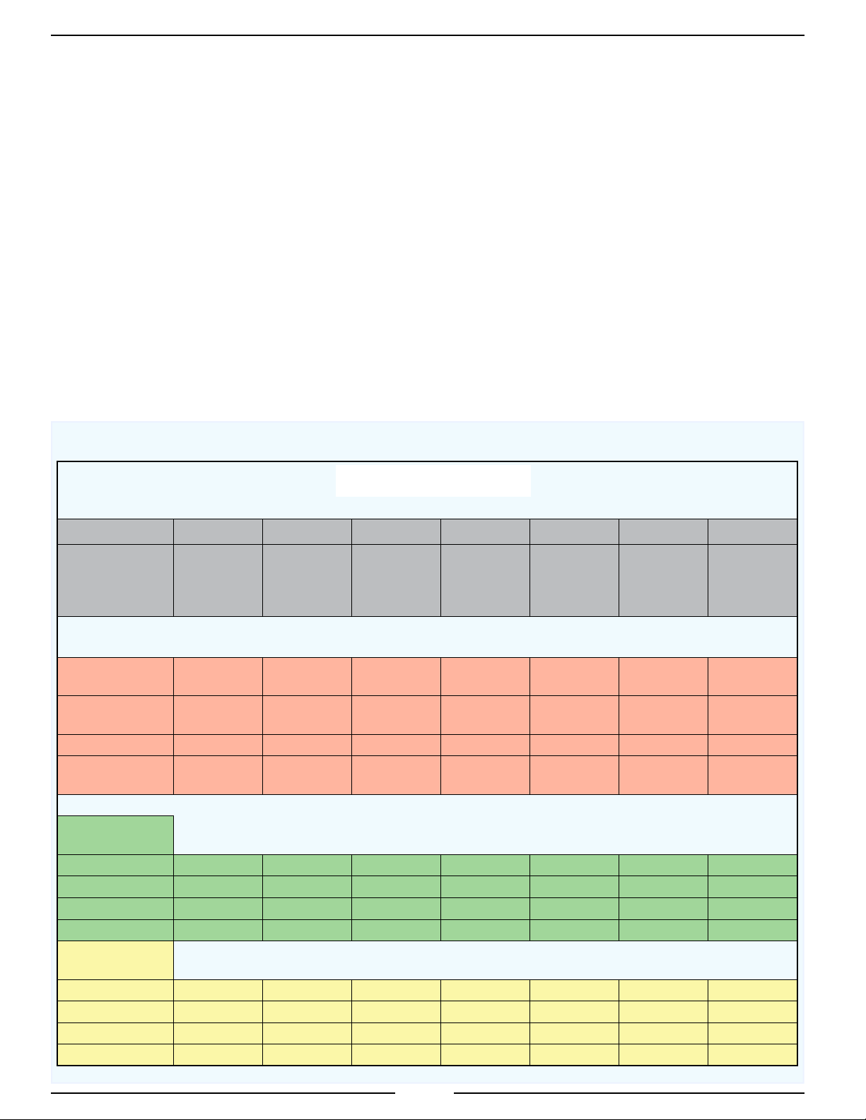
Table 3. Direct Injection Foam Proportioning System Specications
FOAM CONCENTRATE PUMP
1.6 GPM 2.1 GPM 2.6 GPM 3.5 GPM 5.0 GPM 6.2 GPM 6.5 GPM
SYSTEM
MODELS
TFC116
TFC216
TFC316
TFC416
TFC121
TFC221
TFC321
—
TFC126
TFC226
TFC326
TFC426
TFC135
TFC235
TFC335
TFC435
TFC150
TFC250
TFC350
TFC450
TFC162
TFC262
TFC362
TFC462
TFC165
TFC265
TFC365
TFC465
SPECIFICATION
PUMP SIZE
GPM (LPM) 1.6 (6.06) 2.1 (7.95) 2.6 (9.84) 3.5 (13.25) 5.0 (18.93) 6.2 (23.47) 6.5 (24.61)
MOTOR SIZE
(HORSE POWER) 1/3 1 1/2 3/4 1 1 1
DC VOLTAGE 12 or 24 12 or 24 12 or 24 12 or 24 12 or 24 12 24
MAX CURRENT
(AMPS) 36 or 18 90 or 45 50 or 25 68 or 34 78 or 39 90 45
CLASS A FOAM
RANGE: 0.1 to 1.0%
@ 0.1%
@ 0.3%
@ 0.5%
@ 1.0%
CLASS B FOAM
RANGE: 0.5 to 10%
@ 0.5%
@ 3.0%
@ 6.0%
@ 10%
1600 (6057) 2100 (7950) 2600 (9842) 3500 (13249) 5000 (18927) 6200 (23470) 6500 (24605)
533 (2019) 700 (2650) 867 (3282) 1167 (4416) 1667 (6309) 2067 (7824) 2167 (8202)
320 (1211) 420 (1590) 520 (1968) 700 (2650) 1000 (3785) 1240 (4694) 1300 (4921)
160 (606) 260 (984) 260 (984) 350 (1325) 500 (1893) 620 (2347) 650 (2461)
320 (1211) N/A 520 (1968) 700 (2650) 1000 (3785) 1240 (4694) 1300 (4921)
53 (202) N/A 87 (328) 117 (442) 167 (631) 207 (782) 217 (820)
27 (101) N/A 43 (164) 58 (221) 83 (315) 103 (391) 108 (410)
16 (61) N/A 26 (98) 35 (133) 50 (189) 62 (235) 65 (246)
8

GENERAL DESCRIPTION
The TurboFoam system has easy to use push button controls and highly visible displays.
Components
The system consist of the following components (Refer to Figure 1):
Control Module
Foam Pump Assembly
Manual ABF Selector (Option with TFC200 Only)
Electric ABF Selector (TFC400 Only)
Electric Flush Valve (TFC300, Option with TFC100/200)
Miscellaneous Plumbing Components
Discharge Check Valve Assembly (Option)
Discharge Flow Sensor(s) and Sensor Housing(s)
Summing Box (Required with two or more discharge ow sensors.)
TFC100 Rev180215
TankVision Pro or Tank Float Switch (Option)
Flush Switch or Remote ON/OFF Switch and Indicator (Option)
Cables
Control Module
The control module is waterproof. All operational controls and indicators are located on the front of the
control module. (Refer to Controls and Indicators.) A USB port is accessible from the rear of the module.
Foam Pump Assembly
The foam pump assembly provides the correct amount of foam concentrate into the discharge water ow
to make a foam solution. The components of the assembly are attached to the mounting base include an electric
motor and pump, a pump control, a relief valve, and a calibration bypass valve.
Manual ABF Selector (Option)
The manual ABF selector is an option with the TFC200 models. It allows the operator to select Class A foam,
Class B foam, or Flushing operations by rotating the ABF selector handle. The selector is connected between the
foam tanks and the foam pump assembly intake and has an input for ush water. Two check valves are included
with this option that must be installed between the foam tanks and the selector.
Electric ABF Selector
The electric ABF selector is standard on the TFC400 models. It allows the operator to select Class A foam,
Class B foam, or Flushing operations from the push buttons on the control module. The selector is installed
between the foam tanks and the foam pump assembly intake and has an input for ush water. The electric model
is made up of three electric valves mounted on a manifold that controls the ow of foam concentrate or ush
water into the system.
On each of the valve covers there is a dial indicator to show the valve position and an Allen head screw that
allows for manual adjustment of the valve position.
The control box has two status LEDs: A - Not active; B - Blinks one time when a limit switch changes status.
9

TFC100 Rev180215
Electric Flush Valve
The electric valve is standard on the TFC300 models and an option with the TFC100/200 single tank systems.
It is used to provide ush or prime capabilities for the foam concentrate pump.
Miscellaneous Plumbing Components
A check valve is provided for installation on each foam tank line. A strainer is provided for installation on
the input of the foam concentrate pump. A 1/2" water ush line strainer and check valve are provided standard
with systems that include a ush valve.
A tee tting is required to install the electric ush valve, the tee tting is not provided.
A discharge ow sensor with mount and a check valve injector is provided standard with every system.
The optional discharge check valve assembly can be installed that includes the ow sensor, a water way check
valve, and check valve injector.
Discharge Check Valve Assembly (Option)
Two discharge check valve assemblies are available. One includes the ow sensor, water way check valve,
check valve injector, and a drain assembled as a single unit to install. The other includes the water way check
valve, check valve injector, with a drain. These components are all available to be installed separately. (Refer to
Installation Section for plumbing details.)
Discharge Flow Sensor(s)
The standard system has one discharge ow sensor, options with multiple discharge ow sensors are available.
When a single sensor is installed it is usually mounted in the pump discharge manifold to monitor total water ow.
It provides an input signal directly to the control module.
When multiple sensors are installed they are mounted in each discharge. Systems with multiple discharge
ow sensors require a summing box. Each discharge ow sensor is connected to the summing box which in turn is
connected with the FRC datalink to the control module. Multiple mounting options are available for the ow sensor(s).
Summing Box
Note: The summing box is required when there is two or more foam discharge ow sensors.
The summing box is connected between the control module and multiple discharge ow sensors. It provides discharge
ow information to the control module via the FRC datalink. Each summing box has inputs for six (6) ow sensors.
Remote Control Head (Optional)
This additional control head allows for remote operation of the system, and can be placed in another panel on the
truck (away from the primary control head). However, the remote unit cannot be used to change system parameters,
calibrate the system, or view the error/fault history. This can only be done through the primary control head.
TankVision Pro or Tank Float Switch
A TankVision Pro sensor or tank oat switch is required to be installed in the foam tank to provide the tank
empty signal to the control module. The TankVision Pro is connected to the control module on the FRC datalink
and provides tank level data. If tank oat switches are installed, they are connected to the tank empty inputs on
the control module.
Flush Switch and Indicator (Option)
The ush switch is provided with the electric ush valve option for TFC100/200 models. The ush switch
also provides prime capabilities if needed for the concentrate pump.
Remote ON/OFF Switch and Indicator (Option)
The remote switch and indicator mirrors the control module ON/OFF button and LED on the control module.
Cables
Interconnecting cables are provided. (Refer to Wiring Section.)
10
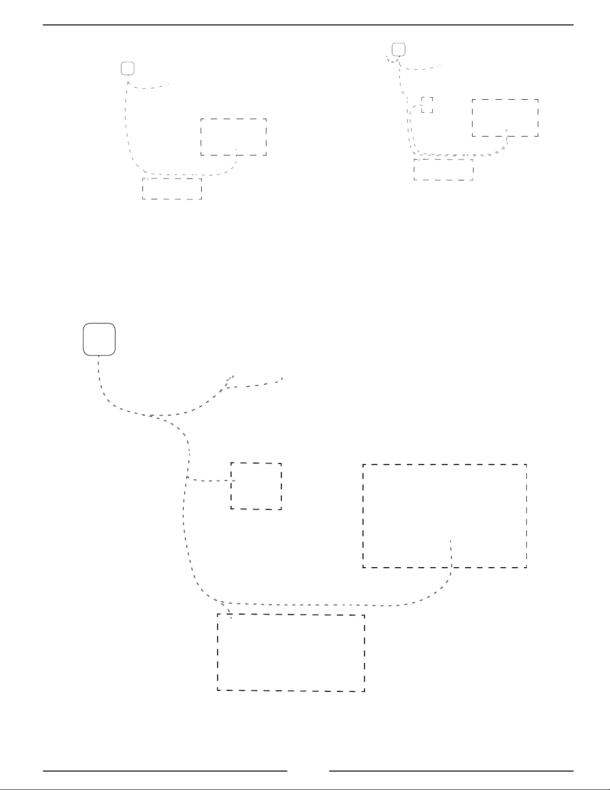
General System Layout
Flush
Switch
TFC100 Rev180215
TFC100 or TFC200
TFC100 or TFC200
Single Tank System
Control
Module
A Foam
Concentrate
Tank
B Foam
Concentrate
Tank
Shutoff
Valve
Check
Valve
Single Tank System
w/Electric Flush
Option
TFC200
Two Tank System
w/Manual ABF Selector
Option
Strainer
Pump Motor
Intake
Water
Flush
Line
Strainer
Check Valve
Water
Pump
Manual ABF
Selector
Calibration
Bypass Valve
Foam
Concentrate
Line
Flow
Sensor
Waterway
Check
Valve
Check
Valve
Injector
Discharge Check
Valve Assembly with
Sensor Mount
Figure 1. General System Layout
11
Pump
Foam Pump
Control
Foam Pump
Assembly
Discharge
TFC100 Rev180215
Notes:
The water ush line may not be necessary
for all single tank systems.
The water ush line can be used for priming
the foam concentrate pump if needed.
It is important that the required check valves
and strainers are installed for all systems.
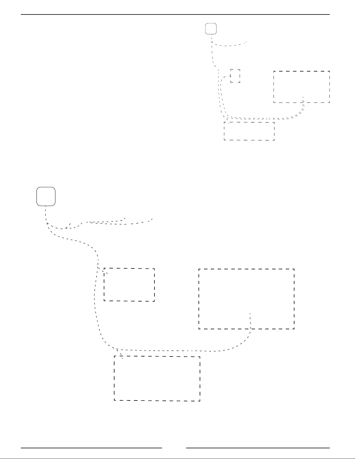
Control
Module
TFC300
Single Tank System
w/Electric Flush Valve
TankVision Pro
Water
Flush
Line
Strainer
A Foam
Concentrate
Tank
Electric ABF
B Foam
Concentrate
Check
Valve
Selector
Concentrate
Tank
Shutoff
Valve
Strainer
Foam
TFC400
Two Tank System
w/Electric ABF Selector
Pump Motor
Pump
Calibration
Bypass Valve
Line
Foam Pump
Control
Foam Pump
Assembly
Intake
Check Valve
Water
Pump
Flow
Sensor
Waterway
Check
Valve
Check
Valve
Injector
Discharge Check
Valve Assembly with
Sensor Mount
Figure 1. General System Layout
12
Discharge

TFC100 Rev180215
Controls and Indicators
All controls and indicators are located on the front of the control module. It contains the push button electronic
controls, LEDs, and digital displays. (Refer to gure.) The buttons are used for operations, reviewing stored data,
and during programming. See Operation and Programming Sections for more information.
ON/OFF Button
Press and hold this button for three seconds to turn the system on. LED goes on. The WATER FLOW display
shows discharge ow rate. A remote ON/OFF switch is available as an option.
PRESET Button
Press this button to set the % foam to a pre-programmed value.
+ / – Buttons
Press the + increase or – decrease buttons to raise or lower the amount of foam concentrate (% foam) that
is mixed into solution. The % display shows the selected percent.
MODE Button (TFC100 Only)
Used to toggle the display mode. A mode LED goes on to indicate the selected display mode. Sets totals to 0.
Mode LEDs (TFC100 Only)
The four LEDs indicate the display mode for the 4-segment display; %FOAM, TOTAL FOAM, FLOW,
and TOTAL WATER.
FOAM EMPTY LED (TFC100 Only)
The input from a TankVision Pro or foam tank level indicator drives this LED.
FOAM % Display
The display shows the selected percent of foam concentrate in the discharge foam solution.
A/B Button (TFC400 Only)
Used to select the A foam or B foam tank. The FOAM A or FOAM B LED goes on for tank selected. When
this button is pressed (with the system is on) a ush cycle automatically occurs before the electric valve switches
the tank (there must be water ow through the discharge).
FLUSH Button (TFC300/400 Only)
Used to operate the ush (or prime) mode. The LED blinks when ush mode is active (there must be water
ow through the discharge).
MENU Button (TFC200/300/400)
Used to access system detailed information, stored data, and program features. Sets totals to 0.
Message Display (TFC200/300/400)
The two line multifunction display shows system information.
When the MENU button is pressed, during calibration, or during programming the display shows codes,
stored data, and program functions.
FLOW Display
The display shows discharge water ow rate through the discharges. In manual mode it shows operator
entered ow rate.
13

TFC100 Rev180215
TFC100
ON/OFF
Button and LED
Display
PRESET
Button
FOAM
EMPTY
LED
Mode
LEDs
MODE
Button
TFC200/300/400
TFC200 does not include the FLUSH button or the A/B button.
TFC300 does not include the A/B button.
+ / –
Buttons
Button and LED
FLOW
Display
Message
Display
MENU
Button
ON/OFF
FOAM %
Display
PRESET
Button
FLUSH
Button and LED
FOAM A
LED
+ / –
Buttons
FOAM B
LED
A/B
Button
Figure 2. Controls and Indicators
14

DIRECT INJECTION
FOAM PROPORTIONING SYSTEM
WITH ELECTRIC FOAM CONCENTRATE PUMP
MODELS: TFC100, TFC200, TFC300, TFC400
OPERATION AND
TFC100 Rev180215
PROGRAMMING
Set Time (Code P109)
Enter password code 1221. (Refer to Enter Password for Program Access.)
1. Press the + and – buttons and scroll to code P109.
2. Press the PRESET button.
Result: The message display shows the time with the hours ashing.
3. Press the + and – buttons to change hours.
4. Press the PRESET button.
Result: The message display shows time with the minutes ashing.
5. Press the + and – buttons to change the minutes.
6. Press the PRESET button.
Result: The message display shows time with the AM/PM ashing.
7. Press the + and – buttons to change the AM/PM.
8. Press and hold the MENU button for ve (5) seconds to save.
FIRE RESEARCH CORPORATION
www.reresearch.com
26 Southern Blvd., Nesconset, NY 11767
TEL 631.724.8888 FAX 631.360.9727 TOLL FREE 1.800.645.0074
15
OPERATION AND PROGRAMMING

TFC100 Rev180215
OPERATION
The TurboFoam system automatically injects foam concentrate into the water ow to provide a consistent
foam solution at the discharge regardless of water ow uctuations.
When power is supplied to the system, the control module FLOW display shows OFF, the message display
shows the date and time or total ow rate for all sensors when a summing box is installed.
When the ON/OFF button is pressed the LED comes on and the control module is active in the auto mode.
The FLOW display shows the water discharge ow rate
The % display shows the last used value or the preset value (based on program code P116).
The message display shows AUTO A(B) and moving arrows to indicate the foam concentrate pump RPM.
With a TankVision Pro connected and program set for tank status (codes P314,P315) the message display
shows the foam type and time remaining at current ow rates A XX.Xm.
Note: The program allows the end user to set the range and the specic increments that are used to
control foam percentage concentration with the + and – buttons.
The PRESET or the + and – buttons are used to adjust the amount of concentrate (changing the percent)
injected into the discharge water ow to create the foam solution. Both of these functions are programmable to
meet the operators requirements.
If a monitored function is not within normal parameters the FLOW display shows an error or fault warning code
and a description shows in the message display. (Refer to Table 5. Error Codes or Table 6. Fault Warning Codes.)
The remote on/off switch and indicator option duplicate the ON/OFF button and LED. The optional ush
on/off switch and indicator controls the optional ush valve.
Detailed Information
TFC100
The TFC100 does not have a message display. Information is shown in a 4-digit display and on four LEDs.
Operations are the same as TFC200/300/400, substitute MODE button for MENU button in procedure steps.
The TFC100 control module four LEDs indicate the display mode for the 4-digit display; %FOAM, TOTAL
FOAM, FLOW, and TOTAL WATER. Press and release the MODE button to toggle through the display modes.
Foam and water totals are reset to 0 when power goes off. When TOTAL FOAM or TOTAL WATER is shown
on the display, press and hold the MODE button to reset total to 0.
TFC200/300/400
The MENU button allows the operator to gain access to detailed information and some programming features.
Press the MENU button to scroll detailed information and return to normal display.
The total water or total foam values can be reset to zero (0) when shown in the display by holding the MENU
button until the number 0 ashes in the display.
The message display reverts to normal operation after ten (10) seconds if no button is pressed.
Table 4. Detailed Information
Message Display Description
T WATER
T FOAM
WATER FLOW Shows water ow rate for each discharge; active only with summing box installed, use the + and – buttons to scroll
TANK A
TANK B
FAULT CODES Shows stored faults with date and time; use the + and – buttons to scroll
INCIDENT REPORT Shows stored incidents with date and time; use the + and – buttons to scroll
* Shows total amount of water ow (in gallons or liters)
* Shows total amount of foam concentrate ow (in gallons or liters)
Shows foam concentrate left in tank A; active only with TankVision Pro Foam A installed
Shows foam concentrate left in tank B; active only with TankVision Pro Foam B installed
*Note: The total water and total foam ow amounts are reset to zero when the system is powered
down. These can be reset during operations if required.
16
TFC100 Rev180215
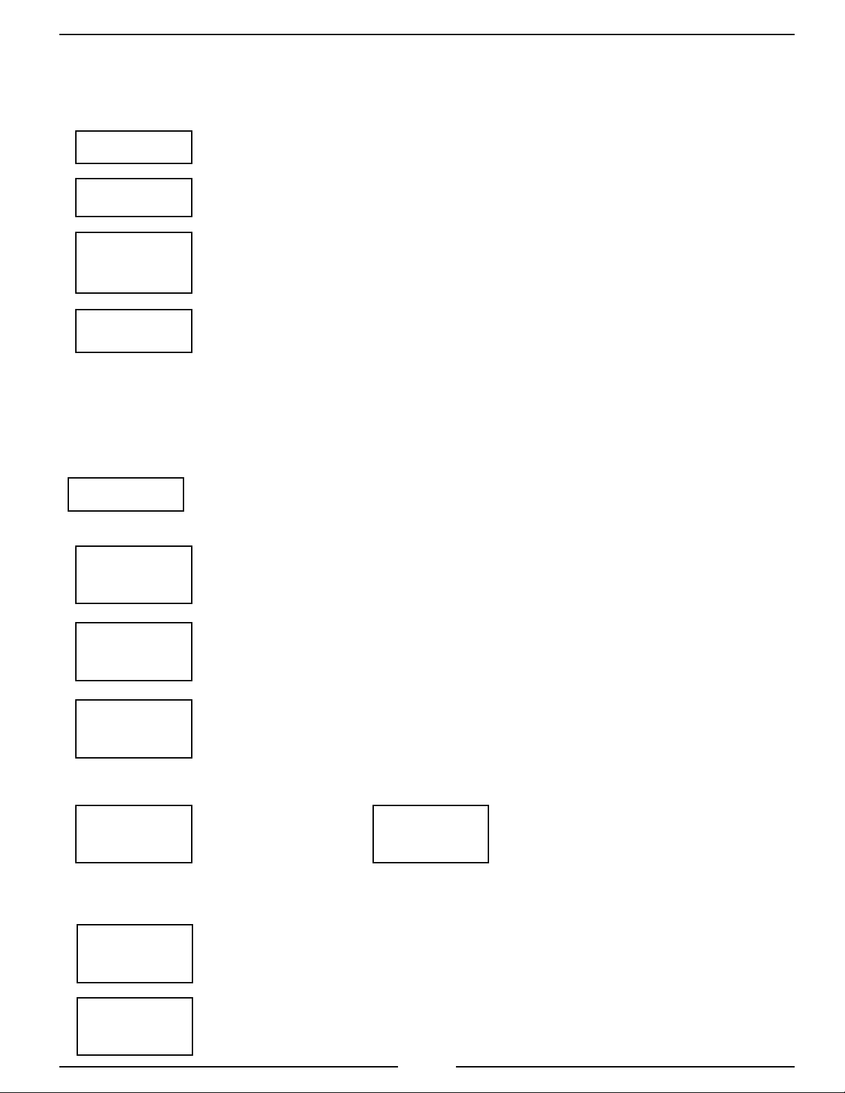
Fault/Error Code Reports
The fault/error code reports show a list of the most recent fault/error codes in reverse chronological order, and
show a maximum of 20 recorded faults/errors. Once the maximum number of 20 is reached, the system will drop
the oldest fault/error in order to make room for a new fault or error.
S 1
Flow Display will show "S" and record number
NOTE: For each fault/error
code, the Fault/Error Code
Report will cycle through
E06
Display shows the descripton for the Fault/Error Code
each screen for approximately
3 seconds.
RPM
SEN
OPEN
04:07 PM
08JUN'16
Display shows the descripton for the Fault/Error Code
Displays the Time of the incident
Displays the Date of the incident
NOTE: Use the INC and DEC
to navigate through the
fault/error reports.
Incident Code Report
The report is displayed in reverse chronological order (works just like the error report). Therefore, the rst
incident indicates the total number of recorded incidents. In the example below the number "10" would indicate
that there 10 recorded incidents. The system will hold a maximum of 20 recorded incidents. Once the maximum
number of 20 is reached the system will drop the oldest incident in order to make room for a new incident.
r 10
Flow Display will show "r" and current record number
The following lines will cycle (about 3 seconds for each screen) per incident:
FOAM A
[blank]
5.3 MINS
3 GALS
03:11 PM
23MAY’16
Line 1 Displays foam type
Line 2
Line 1 Displays the Duration
Line 2 Displays the Foam Volume Dispensed
Displays the Time of the incident
Displays the Date of the incident
NOTE: Use the INC and DEC to navigate
through the error reports.
PCode 324 (Clears the Incident Report). The following depicts screen shots of this process:
CLEAR
INCIDENT
Line 1
Line 2 Press PRESET.
Display will change to:
CLEAR?
NO
“NO” will ash. Use INC or DEC
to toggle between “NO” and “YES”.
Press and Hold MENU to conrm.
PCode 325 (Sets the minimum number seconds the pump must run before recorded as an incident. This prevents
short tests from being recorded.)
INCIDENT
SECS 60
Line 1
Line 2
Press PRESET. Display will ash the least signicant digit and allow the seconds to
be edited. Use the PRESET button to move the ashing eld from one digit to another
and the INC/DEC button to change value. Press and hold MENU to save the setting.
CLEAR?
NO
Line 1
Line 2
“NO” will ash. Use INC or DEC to change “NO” to “YES”. Press and Hold MENU
to conrm.
17

TFC100 Rev180215
Operation Notes
If a tank empty signal goes active the foam pump stops. The pump can be run in override mode by pressing the
ON/OFF button. The warning stays active, the pump should not be run with no foam concentrate owing.
If the foam pump motor RPM sensor information is lost the system operates using a pre-programmed plot based
on the current draw of the motor.
If the ow sensor information is lost the system is operated in the manual mode. Refer to Manual Mode.
To complete ushing the system press the ON/OFF button. (If the FLUSH button is pressed, the system re-starts
auto mode.)
Switching Foam Tanks - Automatic Flush (TFC400 Only)
When the control module is in the auto mode the system performs an automatic ush sequence when switching
between the A foam tank and B foam tank. Discharge water must be owing to cycle through the ush mode.
When switching from A foam tank to B foam tank the A/B button is pressed:
The message display shows A - - - > B and status information, the A tank valve closes then the ush valve
opens, the system ushes for the amount of time set in the programming (default is 8 seconds), the ush
valve closes then the B tank valve opens.
When switching from B foam tank to A foam tank the A/B button is pressed:
The message display shows B - - - > A and status information, the B tank valve closes then the ush valve
opens, the system ushes for the amount of time set in the programming (default is 8 seconds), the ush
valve closes then the A tank valve opens.
Manual Mode
The manual mode is used when ow rate information is not received by the control module. It allows the
operator to manually enter a discharge ow rate for system operations. In the manual mode the foam percent value can
be changed by pressing the MENU button and using the + and – buttons.
Ensure water continuously ows through the discharge during Manual Mode operation.
The manual mode is activated when discharge water is owing but no ow is indicated in the FLOW display.
Note: Ensure there is foam concentrate in the tank, in manual mode there is no auto shut down of the foam
pump if the tank goes empty.
1. Press both the +/– buttons at the same time for 3 seconds to enter manual mode.
Results: MANUAL MODE ashes in the message display for 3 seconds, the message display changes to show
USE +/– FOR FLOW, the FLOW display and red LED ashes. (TFC100 ashes the ON/OFF LED, the
FLOW LED is on.)
2. Press the MENU button and then press PRESET or +/– buttons to adjust the FLOW or FOAM rates.
Results: The FLOW display shows the operator entered ow rate, the system responds to this data and injects the
correct concentrate into the discharge.
3. Press the MENU button to toggle between setting the flow rate and foam percent value.
Press the PRESET button.
Results: The message display changes to show USE +/– FOR %, the FOAM % display ashes.
(TFC100 the % FOAM LED is on.)
Press the + and – buttons to set the %.
Press the MENU button to return to ow rate control.
4. Press the ON/OFF button, the LED goes off; this will stop/start the concentrate pump and shuts down the
TurboFoam system. Press the ON/OFF button again, the LEDs comes on, the system powers on in the
manual mode.
5. Press both the +/– buttons at the same time for 3 seconds to exit manual mode.
NOTE: For the TFC100, substitute MODE button for MENU button in the procedure steps.
18

Error Codes and Fault Warnings
Refer to Calibration, Maintenance, and Troubleshooting Section for detailed information.
Note: The TFC100 does not have a message display. Information is only shown in the 4-digit display.
Table 5. Error Codes
Code TFC200/300/400
Message Display
Description
TFC100 Rev180215
E01 PUMP NOT
DETECTED
E02 MOTOR
OVERLOAD
E03 MOTOR DRIVER
HI TEMP
E04 MOTOR DRIVER
SHUTDOWN
E05 TEMP SEN
FAILED
E06 RPM SEN
OPEN
E07 RPM SEN
SHORTED
E08 MOTOR
FAILED
E09 DRIVER
LIMIT
E10 POWER
LIMITED
E11 NO RPM
DETECTED
E12 NO ABF
DETECTED
E13 FOAM A
VALVE
E14 FOAM B
VALVE
E15 FLUSH
VALVE
E16 FOAM A
VALVE
E17 FOAM B
VALVE
E18 FLUSH
VALVE
E19 FOAM A+B
VALVES
E20 NO MOTOR
POWER
L01 MANUAL
MODE
L02 SVC OIL
FOAMPUMP
L03 FLUSH
SYSTEM
Pump communications failed
Over current condition sensed
Over temperature sensed
Over temperature shutdown; control module to off mode
No temperature sensor signal
RPM sensor failure, circuit open
RPM sensor failure, circuit shorted
Motor not turning; control module to off mode
Hardware power limit, over current protection
Motor does not come up to requested speed, RPM low
No RPM detected from the pump motor
Auto ush communications failed; no auto ush mode
Foam A valve failed to open
Foam B valve failed to open
Flush valve failed to open
Foam A valve failed to close
Foam B valve failed to close
Flush valve failed to close
Auto Flush Valves A+B
Failed to Open
Main Motor Power Lost
Logs manual mode operation
Change pump oil at rst 50 hours than every 500 hours; use code P122 to
clear service oil message
After B foam operation shows as a reminder to ush
19

TFC100 Rev180215
F01-F04: When tank oat switches are used the codes P309 and P310 set the time delay between the tank
low fault warning (F01, F02) and the tank empty fault warning (F03, F04). When a TankVision Pro is
connected the tank low/tank empty information is provided over the datalink. The concentrate pump is
switched off when the tank empty goes active.
Table 6. Fault Warning Codes
Code TFC200/300/400
Message Display
F01 FOAM A
LOW
F02 FOAM B
LOW
F03 FOAM A
EMPTY
F04 FOAM B
EMPTY
F05 SYSTEM
AT MAX
Description
A foam concentrate low
B foam concentrate low
A foam concentrate tank empty; control module to off mode
B foam concentrate tank empty; control module to off mode
Request exceeds foam concentrate pump capacity
Preset Settings
The preset button allows the operator to go to a pre-programmed percent setting during operations.
The preset value shows in the % display.
Note: The preset setting (selected when the PRESET button is pressed) can only be set to a program
enabled value. Refer to Programming Section for information on Set +/– Increment Value, codes
P118 and P119.
To access the preset setting program the discharge ow must be 0 (FLOW display shows 000).
1. Select A foam tank or B foam tank.
For dual tank systems. TFC200 set the manual ABF selector; TFC400 press the A/B button.
For single tank systems this is set with program code P312.
2. Press and hold PRESET button. (Continue to hold through step 4.)
Result: % display ashes the programmed setting.
3. Press the + and – buttons to change setting.
4. Release PRESET button.
Result: The new preset value is programmed.
20

TFC100 Rev180215
PROGRAMMING
Programming functions are allowed when the control module is in the off mode. All program functions are
password protected.
The P-code program functions are available to view and change after the password code has been entered.
Scroll through the P-codes. Use the PRESET button to enter the programming mode and select specic values
(number, word, or symbol) to change. The value blinks and the + and – buttons are used to change that value.
Note: To exit programming modes, press and hold the MENU button for ve (5) seconds.
Enter Password for Program Access
Note: The TFC100 does not have a message display. Information is only shown in the 4-digit display,
procedures are the same. (Substitute MODE for MENU button.)
1. Press and hold the + button for 3 seconds. The FLOW display shows four dashes – – – – and the
message display shows ENTER CODES. Release the button.
2. Press the + and – buttons to enter a code. Each time a button is pressed the rst digit changes by 1.
Set the rst digit to the desired number.
3. Press the PRESET button to move the curser to the next digit. Press the + and – buttons to change
the digit.
4. Repeat step 3 and enter the password code.
Result: When a correct password code is entered the FLOW display ashes the program (P) code and
the message display shows the name of the program or a description of the program code.
5. Press the + and – buttons to scroll through the codes.
6. Use the PRESET button to enter the programming mode and select specic values to change, the +
and – are then used to change the value, the MENU button is used to save the changes.
7. Press and hold the MENU button for ve (5) seconds to exit.
Calibration Passwords 1111 and 1112
Provides access to system programming required for calibration procedures.
1111 - Calibrate Discharge Flow Sensor(s)
1112 - Calibrate Foam Pump
Refer to Calibration Section.
Operator Password 1221
Provides access to system programming P100 codes.
1221 - Operator Programs
Refer to Operator P100 Codes.
Restore Programmed Functions Passwords 5122 and 5123
Provides access to upload all system programming and calibration information from one component to another.
5121 - Initiates Synchronization Between Control Module and Foam Pump Control Programs
5122 - Set/Clear Control Module Restore Flag
5123 - Set/Clear Foam Pump Control Restore Flag
Refer to Restore Programmed Functions Section.
21

TFC100 Rev180215
OEM/Dealer Password Restricted (Contact FRC)
Provides access to system programming P300 codes.
Password Restricted - OEM/Dealer Programs
For more information, refer to the OEM/Dealer P300 Codes listed in the separate OEM programming manual.
22

TFC100 Rev180215
Operator P100 Codes
The TFC100 does not have a message display. Information is only shown in the 4-digit display, procedures
are the same. (Substitute MODE for MENU.)
When scrolling through the P-codes, some may not be displayed. This happens when a specic code is not
available for access because of other programming settings. (Example: If a system is set for a single A foam tank,
program codes for a B foam tank are not displayed.)
Notes:
1 - Codes P108 and P109: For detailed instructions refer to Set Date and Time.
2 - Code P110: This code is only available when a system has multiple discharge ow sensors. If no
ID names are programmed, the system assigns FLOW 1, FLOW 2, FLOW 3, etc., based on each ow
sensor input connection to the summing box(es). For detailed instructions refer to Set Discharge Flow
Sensor ID Names.
3 - Codes P111 and P115: These codes are used to access information that is stored in various system
devices such as the serial number, manufacture date, or hardware and rmware revisions of that component.
They are only available if the device is detected on the FRC datalink.
4 - Code P116: This code sets the % value when the system is powered on or when switching between
A and B foam tanks (TFC200/400). It can be programed to PRESET (the programmed preset value) or
LAST VAL (the last used value set by the operator).
5 - Code P117: With this code is set to AUTO when power is applied the system the control module is
active and the system is in auto mode (operational).
6 - Codes P118 and P119: These codes are used to set the increment steps when the + and – buttons are
pressed. For two tank systems values for both foam A and foam B are set. (TFC200/300/400 shows YES
or NO in the message display, the TFC100 uses the % FOAM LED ; on = yes, off = no.) For detailed
instructions refer to Set +/– Increment Value.
7 - Code P120: This code allows the end user to adjust the elapsed time that passes before the -operate
system warning- goes active. It is recommended that the system be operated at least once every 6 weeks
(42 days). If the concentrate pump is not operated within the set time frame, a message OPERATE
FOAMPUMP shows in the display. The elapsed time clock resets after each pump operation.
8 - Code P122: This code is used to clear the L02 service reminder. The concentrate pump oil must be
changed after the rst 50 hours of operation and then every 500 hours. When these time markers are hit,
the L02 code and the message SVC OIL FOAMPUMP shows in the display. When the oil is changed
access code P122 and set it to YES, this clears the service needed message.
23
TFC100 Rev180215
CODE
DESCRIPTION
Password Code: 1221
Notes
Enables Access to P100
Table 7. Program Functions P100 Codes Quick Reference
TFC100
DISPLAY
Factory Default
Shown
TFC200/300/400
MESSAGE DISPLAY
Factory Default Shown
Press PRESET button to select;
change value with + or – button,
Press (MODE) MENU to set value
P101
P102
P103
P104
P105
P106
P107
P108
P109
P110
P111
P112
P113
P114
P115
P116
P117
P118
P119
P120
P121
P122
System Model
Software Revision
Manufacturing Date
Serial Number
Hardware Version
UID Number - Upper
UID Number - Lower
Current Date
1
Current Time
1
Assign ID Names for Discharge
2
Flow Sensors w/Summing Box
Pump Device Data
3
Summing Box 1 Device Data
3
Summing Box 2 Device Data
3
Summing Box 3 Device Data
3
Auto Flush Device Data
3
Proportioning Rate at Power Up or
4
when Switching Between A and B
Control Module Mode at Power Up
5
Set +/– Percent Increment Value
6
Foam A
Set +/– Percent Increment Value
6
Foam B
Days to Exercise Concentrate
7
Pump
Display Concentrate Pump Hours
Clear Oil Service Reminder (Error
8
Code L02)
tFC-<>
100
MODEL
TFC###
r#.## PROG REV
###.##
MM.YY MFG DATE
DDMMM'YY
#.### <>
##.#
SER NO
######
### HW REV
###
##<>##<>## UIDUPPER
##-##-##
N/A UIDLOWER
##-##-##
DD.MM <>
Yr.YY
HH N <>
NN
SET DATE
DDMMM'YY
SET TIME
HH:MM AM/PM
N/A SET FLOW
#### <>
####
PUMP
INFO
N/A SUMBOX 1
INFO
N/A SUMBOX 2
INFO
N/A SUMBOX 3
INFO
N/A AUTOFLSH
INFO
PrES SEL FOAM
PRESET
OFF POWER UP
OFF
0.1
LED On
0.1
LED Off
FOAM A
0.1% YES
FOAM B
0.1% NO
N/A OP PUMP
DAYS 42
## PUMP HRS
###
no CLEAR
OIL SVC
(Read Only)
(Read Only)
(Read Only)
(Read Only)
(Read Only)
(Read Only)
(Read Only)
Refer to Set Date
Refer to Set Time
Refer to Set Discharge Flow Sensor
ID Names
LAST VAL
PRESET
AUTO
OFF
0.1 to 0.9 then 1.0 to 10 Increments
Select YES or NO for Each
0.1 to 0.9 then 1.0 to 10 Increments
Select YES or NO for Each
Set Number; 0 = Disable Function
YES
no
24

Set Date and Time
Note: The TFC100 does not have a message display. Information is only shown in the 4-digit display,
procedures are the same. (Substitute MODE for MENU.)
Set Date (Code P108)
Enter password code 1221. (Refer to Enter Password for Program Access.)
1. Press the + and – buttons and scroll to code P108.
2. Press the PRESET button.
Result: The message display shows the date with the day ashing.
3. Press the + and – buttons to change the day.
4. Press the PRESET button.
Result: The month ashes.
5. Press the + and – buttons to change the month.
6. Press the PRESET button.
Result: The year ashes.
7. Press the + and – buttons to change the year.
TFC100 Rev180215
8. Press and hold the MENU button for ve (5) seconds to save.
Result: The message display shows DONE.
Set Time (Code P109)
Enter password code 1221. (Refer to Enter Password for Program Access.)
1. Press the + and – buttons and scroll to code P109.
2. Press the PRESET button.
Result: The message display shows the time with the hours ashing.
3. Press the + and – buttons to change hours.
4. Press the PRESET button.
Result: The message display shows time with the minutes ashing.
5. Press the + and – buttons to change the minutes.
6. Press the PRESET button.
Result: The message display shows time with the AM/PM ashing.
7. Press the + and – buttons to change the AM/PM.
8. Press and hold the MENU button for ve (5) seconds to save.
Result: The message display shows DONE.
25

TFC100 Rev180215
Set Discharge Flow Sensor ID Names (TFC200/300/400)
This code applies to systems with multiple foam discharge ow sensors and a summing box installed. There
are twelve (12) names along with a two digit number that can be used to identify each foam discharge ow sensor.
If no ID names are programmed for the sensors, the factory defaults are FLOW 1, FLOW 2, FLOW 3, etc.,
based on the location of each ow sensor input connection to the summing box(es)
The summing boxes are identied, when the code is selected, and shown on the control module display as
Sb #.# (#'s refer to box and input). The following example shows two summing boxes with a total of nine inputs:
First box six inputs Sb 1.1, Sb 1.2, Sb 1.3, Sb 1.4, Sb 1.5, Sb 1.6
Second box three inputs Sb 2.1, Sb 2.2, Sb 2.3.
The factory default ID name shown in the message display for the above example is FLOW 1 through
FLOW 9.
Set Flow ID Name (Code P110)
Enter password code 1221. (Refer to Enter Password for Program Access.)
1. Press the + and – buttons and scroll to code P110.
2. Press the PRESET button.
Result: The % display shows Sb 1.1, 1.1 ashes indicating summing
box 1, input 1, message display shows the ID name.
3. Press the PRESET button (or press the INC or DEC button to scroll
inputs).
Result: The message display ashes the ID name.
4. Press the + and – buttons to scroll the ID names.
5. Press the PRESET button to choose a name.
Result: The message display ashes the ID number. (See Note)
6. Set the number (press the + and – buttons to change the digit, press
the SELECT button to move the curser to the next digit).
7. Press the MENU button to return to step 3.
8. Press and hold the MENU button for ve (5) seconds to save.
MESSAGE
DISPLAY
DIS.
##
F DIS.
##
REAR DIS
##
L/R DIS
##.
R/R DIS.
##
DECK GUN
##
ROOF TUR
##
CROSSLAY
##
PCON
##
L/R PCON
##
R/R PCON
##
FLOW
##
DESCRIPTION
Discharge
Front Discharge
Rear Discharge
Left Rear
Discharge
Right Rear
Discharge
Deck Gun
Roof Turret
Crosslay
Pre-Connect
Left Rear
Pre-Connect
Right Rear
Pre-Connect
Factory default
ID name
Note: If FRC owmeters (DFA or FPA) are used to retrieve ow rate
information, only the FRC Datalink is connected to the foam system.
IMPORTANT the owmeter ID numbers must be different than the
ow sensor ID numbers used with a summing box.
26

TFC100 Rev180215
Set +/– Increment Value
P118 and P119 codes are available dependent on the setting of code P312. For single tank foam A systems
code P118 is programmable, for a single tank foam B code P119 is programmable. For two tank systems both
P118 and P119 are programmable.
The following percent values are available:
0.1, 0.2, 0.3, 0.4, 0.5, 0.6, 0.7, 0.8, 0.9, 1.0, 2.0, 3.0, 4.0, 5.0, 6.0, 7.0, 8.0, 9.0, 10
Example: A system is programmed with code P312 to SINGLE B. This is a foam B system only
where a 1, 3, or 6% mixture is used. Code P119 is set with 1.0, 3.0, and 6.0 YES to enable these
three values, all the rest of the values are set to NO. When the operator presses PRESET or the
+ and – buttons only the 1.0, 3.0, and 6.0 foam percents are available.
Notes:
These codes allow the end user to set the range and the specic increments that can be used to control
foam percentage concentration.
The software requires that at least one value is set to YES.
The preset and last used value can only be one of the set values. (The software checks that the current preset
and the last used value matches a set value. If not, the software changes it to the lowest value set at yes.)
The TFC100 does not have a message display. Information is only shown in the 4-digit display, procedures
are the same. (Substitute MODE for MENU.)
Set +/– Increment (Code P118 or P119)
Note: TFC200/300/400 shows YES or NO in the message display, the TFC100 uses the % FOAM
LED ; on = yes, off = no.
Enter password code 1221. (Refer to Enter Password for Program Access.)
1. Press the + and – buttons and scroll to code P118 or P119.
2. Press the PRESET button.
Result: The message display shows the % value.
3. Press the PRESET button to select YES or NO.
4 Press the + and – buttons to scroll to the next value. Repeat steps 3 and 4 to set all values.
5 Press and hold the MENU button for ve (5) seconds to save.
27
 Loading...