


Document Number:
XE-SNB2-TH6PM-R0A
TH6 Hybrid
6-Camera System
Installation and Setup Guide
© Safe Fleet | May 2019 | All rights reserved

TH6 Installation and Setup Guide
— this page intentionally left blank —
p. 2
© Safe Fleet | May 2019 | All rights reserved
Document Number: XE-SNB2-TH6PM-R0A

TH6 Installation and Setup Guide
Contents
Contents
Section 1 — Installation pg. 5
Installing the DVR
Installing the Signals Harness
Installing the Expansion Harness
Installing the SD Card
Hardware Installation Checklist
Firmware Updates
Copying DVR Conguration
Section 2 — Operation pg. 17
DVR Front Panel Features
DVR Back Panel Features
Video System Status
Tagging Video for Review
Section 3 — Basic Conguration
pg. 31
Setting Up the DVR
Time/Date Menu
Title/Display Menu
Camera Settings
Signals
Alarms
Section 4 — Advanced
Conguration pg. 45
Recording Settings
Network Settings
Advanced Network Settings
Accessing On-screen Display
Using On-screen Keyboards
Working with Video
Health Check
VMS Servers
G Sensor
Speed Settings
GPS Fencing
User Levels
System Settings
Program Update
Monitor Settings
Wake on Input, Digital Output
p. 3
© Safe Fleet | May 2019 | All rights reserved
Document Number: XE-SNB2-TH6PM-R0A
TH6 Installation and Setup Guide
i
Introduction
Introduction
This Guide provides the following information for Installers, System Technicians, and Vehicle Operators working with
the TH6 DVR system:
Installers
Explore the TH6 DVR system components, physical and electrical installation, and system-level settings, including
camera and DVR conguration. You'll also learn to test system functionality and interoperability with other
equipment, how to clone DVR conguration, and performing rmware updates.
NOTE: Professional Installation
DVR systems must be installed by a professional installer with the appropriate experience and equipment.
System Technicians
Help troubleshoot and maintain the mobile surveillance system using a monitor plugged into the DVR front panel,
remove and replace hard drives, access video, and set up cameras and recording options.
Note: on-screen conguration and video playback requires a portable video monitor and a USB mouse.
Vehicle Operators
Learn how to ag an event so incident video can be easily located, and understand the system status indicator, so
you'll know when the DVR is recording.
p. 4
© Safe Fleet | May 2019 | All rights reserved
Document Number: XE-SNB2-TH6PM-R0A

TH6 Installation and Setup Guide
Installation
Installing the DVR........................................................................................................... 6
Tools and Equipment ...............................................................................................................6
Physical Location .....................................................................................................................6
Installation Requirements ........................................................................................................7
Physical Installation .................................................................................................................7
Installing the Signals Harness ....................................................................................... 9
Installing the Expansion Harness (optional) .............................................................. 10
Installing the SD Card (optional) .................................................................................11
Installation
Hardware Installation Checklist ................................................................................... 12
Firmware Updates ........................................................................................................ 13
Firmware Version ...................................................................................................................13
To install a rmware update: ..................................................................................................13
Copying DVR Conguration ........................................................................................ 14
Copying DVR Settings ...........................................................................................................14
Applying DVR Settings ..........................................................................................................15
p. 5
© Safe Fleet | May 2019 | All rights reserved
Document Number: XE-SNB2-TH6PM-R0A

TH6 Installation and Setup Guide
Installing the DVR
Installing the DVR
Tools and Equipment
The DVR system must be installed by a professional installer. A professional installer has the experience and
equipment to install and congure this DVR system to run properly.
Check that you have all the system components and inspect the units for any scratches or damage before installing.
Keys included in package contents:
• DVR keys for securing the removable hard drive
• Front cover keys for securing the removable front cover
Conguration equipment:
For on-screen conguration: portable video monitor and mouse
• For vMax Web conguration: laptop and an Ethernet cable
Physical Location
The DVR is secured with a security front cover and a cable cover. The cable cover allows wiring to enter from the
underside of the back of the unit.
The DVR is designed for horizontal installation, on top of the mounting plate (see the diagram on page 8), but
may be installed vertically if required. Do NOT install the DVR upside down.
WARNING: Risk of Heat or Moisture Damage
Do not install the DVR in a location where the unit is exposed to excessive heat or moisture.
Installation close to extreme heat or moisture voids the product warranty.
Route wiring and cables away from sharp edges that might damage the insulation. Avoid sharp bends in the
cable.
Contact Technical Support before attaching the DVR to other equipment in the vehicle.
Before installing the DVR, keep in mind that a well-ventilated location and sufcient clearance around the unit are key
factors for performance and maintainability. The following table provides information on installation requirements.
!
p. 6
© Safe Fleet | May 2019 | All rights reserved
Document Number: XE-SNB2-TH6PM-R0A
TH6 Installation and Setup Guide
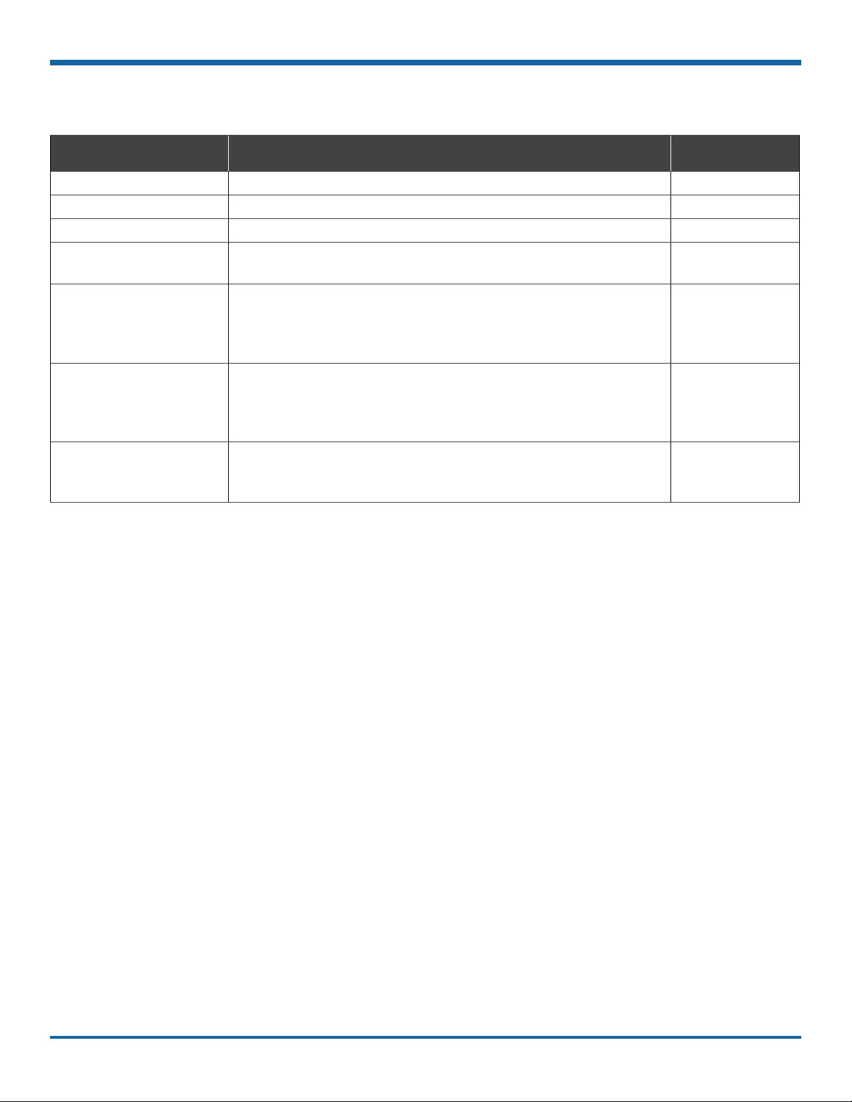
Installation Requirements
Installing the DVR
WARNING: Safety and Electrical Systems
It is your responsibility to avoid damaging safety or electrical systems.
Ventilated
Location
Mount to
secure
surfaces
only
Mounting
orientation
Clearance
around the
DVR
Mounting
cables
Ethernet
cables
Install the DVR away from any sort of heat outlet, heater, or AC blower. Do not operate the DVR
in a closed-in area or restrict ventilation in any way. The DVR requires air circulation to maintain
optimum operation temperature and provide best performance. Do not expose the DVR to
moisture.
Do not mount the DVR to a plastic panel or other surface that is subject to constant vibration.
We strongly recommend mounting the DVR in a horizontal orientation (on top of the mounting tray);
however, to accommodate space restrictions, vertical mounting is acceptable. Do NOT install the
DVR upside-down.
Allow sufcient clearance of at least six (6) inches in front of the DVR and two (2) inches to each
side for removal of the security front cover and easy access to the hard drive and USB ports. Allow
sufcient clearance behind the DVR for camera cables, mounting cables, Ethernet cables, and
power cables.
The radius for the mounting cables will be dictated by the cable cover. The rearmost surface of the
cable cover will be about 3 inches from the back of the DVR to allow camera cables to bend over
each other.
Avoid right angle bends in the Ethernet cables.
!
Power
cables
Provide enough slack on the power cable to prevent any force from being exerted on the
connectors. A single 4-inch diameter loop is sufcient.
Physical Installation
The DVR typically ships with the locking front cover, mounting plate, and cable cover off, but in the shipping box.
The hard disk drive is in a separate box in the system shipping kit.
To install the DVR:
1. Select an appropriate mounting location and
orientation (horizontal or vertical).
2. Insert a hard drive in the DVR.
3. Insert the key into the hard drive lock and rotate a
quarter turn to lock the drive.
p. 7
© Safe Fleet | May 2019 | All rights reserved
Document Number: XE-SNB2-TH6PM-R0A

TH6 Installation and Setup Guide
4. Use the mounting plate to mark the desired position
of the DVR and drill the four mounting holes.
5. Fasten the mounting plate to the mounting surface
with the four self-drilling screws.
6. Slide the rear bottom edge of the DVR into the
spring tab on the back edge of the mounting tray.
7. Attach the front bottom edge to the front of the
DVR using the two pan-head Phillips screws.
8. Connect the necessary cables and components.
For more information, see "DVR Front Panel
Features" on page 18 and "DVR Back Panel
Features" on page 19.
9. Attach the cable cover to the DVR using the thumb
screws provided.
10. When DVR installation is complete, attach the front
door by hooking the door along the top edge and
turning the key to the locked position.
Installing the DVR
p. 8
© Safe Fleet | May 2019 | All rights reserved
Document Number: XE-SNB2-TH6PM-R0A
TH6 Installation and Setup Guide
Installing the Signals Harness
Installing the Signals Harness
About
This topic describes installing the Signals Harness, which connects the DVR to Signal inputs, and to the optional
Event/Diagnostic button and Wake on Input trigger: for more information on each of these features see:
• "Signals" on page 41
• "Tagging Video for Review" on page 22
• "Wake on Input, Digital Output" on page 68
Before you begin...
It is your responsibility to avoid damaging safety or electrical systems.
Ensure you read and understand "Installation Requirements" on page 7.
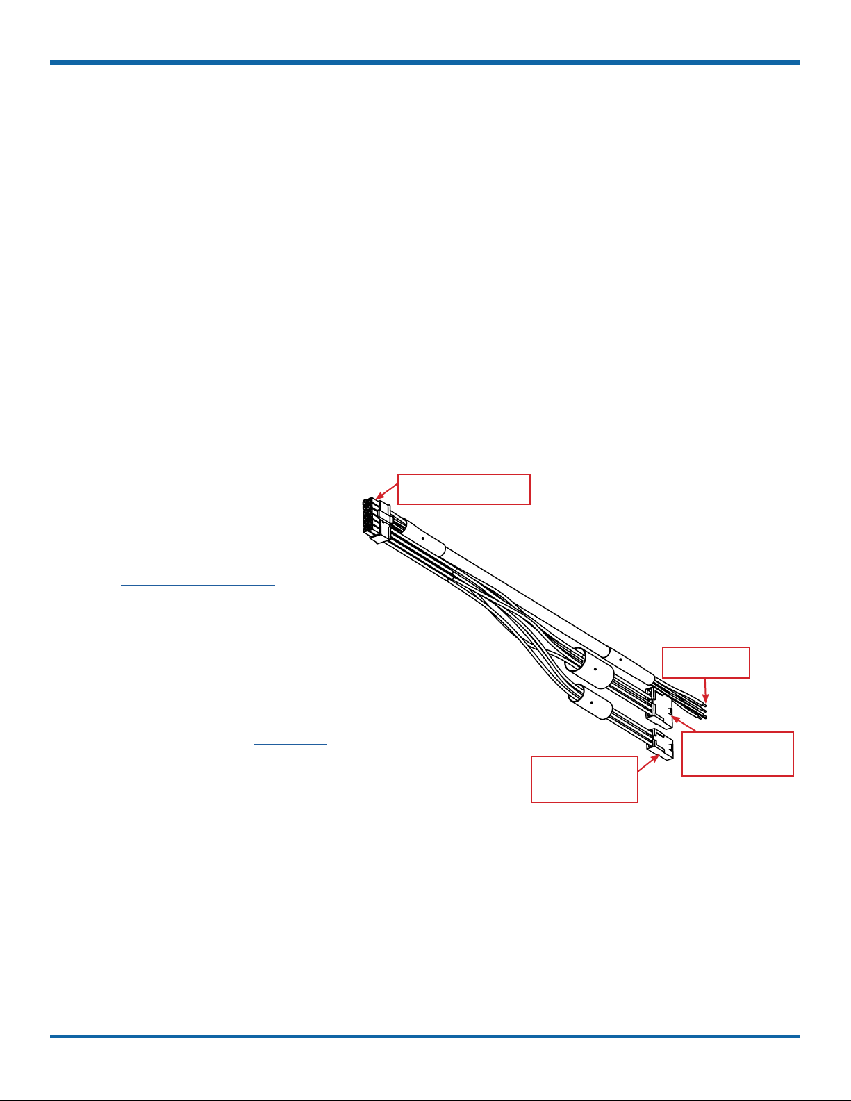
To install the Signals Harness
Connect the 2x6 Microt to the SIGNALS
socket on the DVR.
• Connect the 5 signal input wires, as
shown in the in the Installation Diagram
in the TH6 Quick Install Guide on the
inView Guardian product page.
• Connect the 1x5 Microt to the Adapter
harness for the Event/Diagnostic button
(optional).
• Remove the 1x3 Microt and connect
the green and black wires to a Wake on
Input trigger (optional) as shown in the
Installation Diagram in the TH6 Quick
Install Guide on the inView Guardian
product page.
The Signals harness is Part # WT1.
To DVR SIGNALS socket
(2 x 6)
To Wake on Input
trigger - optional
(1 x 3)
To Signal
inputs (5 wires)
To Event/Diagnostic
button - optional
(1 x 5)
p. 9
© Safe Fleet | May 2019 | All rights reserved
Document Number: XE-SNB2-TH6PM-R0A

TH6 Installation and Setup Guide
Installing the Expansion Harness (optional)
Installing the Expansion Harness (optional)
About
This topic describes installing the optional Expansion Harness, which can connect the DVR to Student Tracking
and Rear Vision systems, and provides a digital output to trigger other devices when an Alarm is detected (for more
information, see "Alarms" on page 43.
Before you begin...
It is your responsibility to avoid damaging safety or electrical systems.
Ensure you read and understand "Installation Requirements" on page 7.
To install the Expansion Harness
Connect the 2x4 Microt connector to the
EXPANSION socket on the DVR.
• Connect the 4-pin to the Student
Tracking harness (optional).
• Connect the 2-pin to the Rear Vision
System harness (optional).
• Connect the Digital Out black and
blue wires (optional) as shown in the
Installation Diagram in the TH6 Quick
Install Guide on the inView Guardian
product page.
The Expansion Harness is Part #060-1059
p. 10
© Safe Fleet | May 2019 | All rights reserved
Document Number: XE-SNB2-TH6PM-R0A
TH6 Installation and Setup Guide
Installing the SD Card (optional)
Installing the SD Card (optional)
About
This topic describes installing the optional SD card, a secondary storage device used to record the DVR's low
resolution (and low frame rate) stream, providing backup storage to the SD card. The amount of backup storage
available from the card is determined by the card's capacity.
TIP: Repeat Record setting controls SD card "looping"
The Conguration Record Repeat Record setting determines what happens when the SD card
becomes full. The default is to loop (record over the oldest video).
For more information, see "Recording Settings" on page 46.
Only the lower resolution "Record 2" video stream is stored on the SD card. Access to the recording on the SD card
is only possible through vMax View, since the card is intended for backup purposes.
To install the SD card:
1. On the front of the DVR, remove the screw holding
the SD card cover plate, and remove the plate.
2. Remove the adhesive plastic shipping strip
covering the SD card slot.
3. Insert a Seon-approved SD card into the slot until
it clicks.
4. Replace the SD card slot cover plate.
p. 11
© Safe Fleet | May 2019 | All rights reserved
Document Number: XE-SNB2-TH6PM-R0A
TH6 Installation and Setup Guide
Hardware Installation Checklist
Hardware Installation Checklist
√
√
√
Harnesses (camera, recorder, and accessories)
Ensure cables and harnesses are properly secured.
Check that sharp metal edges are not touching cables or harnesses.
Ensure connections are solid (no shorts).
Cameras
Ensure tight mounting.
Examine the internal harness connections and ensure they are solid.
Ensure the lid is properly seated on the gasket and secured tightly.
Check camera(s) eld of view.
DVR
Ensure tight mounting.
Check that all connections are tight.
√
System
Install fuses.
Plug portable video monitor into DVR, and power up the DVR from the vehicle ignition.
Congure the DVR to required specications locally using the mouse and monitor, or remotely by
accessing vMax Web via WiFi or Ethernet using a PC.
For more information, see "Basic Conguration" on page 31
Conrm the LAN, HDD, and PWR status indicators on the DVR front panel work properly.
Conrm that all cameras and audio sources operate properly.
Test audio/video record and playback.
Reformat the hard drives by navigating to Main Menu Conguration System Program
Update Format.
A warning message tells you all data will be erased. Click Yes. When the process completes and
a message appears, click OK. Exit the Conguration setting menu, and system setup is complete.
Fasten and lock the front cover. Secure the cable cover on the DVR using the screws provided.
p. 12
© Safe Fleet | May 2019 | All rights reserved
Document Number: XE-SNB2-TH6PM-R0A

TH6 Installation and Setup Guide
!
!
Firmware Updates
Firmware Updates
About
This topic describes how to install a DVR rmware update. Firmware controls how DVR features operate, including
the Playback and Conguration menu displays. Technical Support may direct you to install a rmware update when
new features are added or specic issues are addressed.
Before you begin...
Contact Technical Support to obtain the latest rmware update for your DVR. Copy the update le to a USB storage
device formatted by a Windows-based computer using the FAT le format.
Firmware Version
The current rmware version appears in the top-right
corner of every Conguration menu.
For instructions on opening the Conguration menus,
see "Accessing the On-screen Display" on page 23.
IMPORTANT: Firmware Updates
Only install rmware updates as directed by Technical Support
To install a rmware update:
1. Power-up the DVR using the vehicle ignition.
2. Insert the USB memory device with the new
rmware version into the USB port on the DVR.
3. After the DVR starts up, right-click in the On-screen
Display and select
Conguration System Program Update.
4. In the Program Update tab, click Update.
A conrmation window appears.
5. Click Yes to proceed or No to cancel.
Yes starts the rmware update, and a progress bar
displays the percentage complete.
6. Once the update is nished, the DVR automatically
restarts.
WARNING: Do not crank the vehicle power or remove
power while updating the DVR rmware.
Equipment damage may result.
NOTE: After restarting, the DVR may take up to 3
minutes to load and complete the upgrade.
Wait until the DVR nishes loading.
7. Remove the USB memory device.
p. 13
© Safe Fleet | May 2019 | All rights reserved
Document Number: XE-SNB2-TH6PM-R0A

TH6 Installation and Setup Guide
Copying DVR Conguration
Copying DVR Conguration
About
This topic explains how to copy setup details from a DVR and apply them to other DVRs. This capability saves a lot
of time and effort, and ensures consistent conguration when installing and maintaining DVRs in a eet.
Before you begin...
Ensure the DVR you're copying conguration from is set up properly. For more information, see "Setting up the
DVR" on page 32.
This procedure requires physical access to the DVR you want to copy settings from, a portable video monitor, a
USB mouse, and a USB storage device formatted by a Windows computer using the FAT. You should have a
general understanding of mobile surveillance system components, and experience with Windows-based computers
and storage media.
What are Conguration Files?
A conguration le preserves a particular DVR setup, so you can apply the settings to other DVRs in a
single operation. You create a named conguration le, which contains all a DVR's current Conguration menu
settings. If you need more than one system setup for your eet (for example, a specic number of cameras and
viewpoints for different vehicle congurations), build a separate conguration le for each situation.
You can load a conguration le onto DVRs during installation or when changes are required, and all settings are
applied automatically.
Copying DVR Settings
Before copying conguration, ensure the DVR is set up for specic vehicle type and mobile surveillance
requirements, including camera names/channels, recording parameters, Alarm and Signal assignments, system
preferences, and networking details. For more information, see "Setting up the DVR" on page 32.
This procedure requires physical access to the DVR you want to copy settings from, a portable video monitor, a
USB mouse, and a USB storage device formatted by a Windows computer using the FAT.
p. 14
© Safe Fleet | May 2019 | All rights reserved
Document Number: XE-SNB2-TH6PM-R0A

TH6 Installation and Setup Guide
!
To create a conguration le:
1. Insert the USB storage device in the USB port on
the DVR's front panel. For more information, see
"DVR Front Panel Features" on page 18.
2. Access the OSD (On-Screen Display). For
details, see "Accessing the On-screen Display"
on page 23.
3. Right-click anywhere in the OSD view to access
the Main Menu.
4. Select Conguration System
Program Update.
5. In the Store Current Conguration to: pull-down
menu, select USB Device.
6. Click the File Name eld and use the on-screen
keyboard to change the conguration le name
(maximum 4 characters).
Best practice is to choose a name that references
the eet and/or conguration type (e.g. "SB5C" for
a school bus with 5 cameras).
Copying DVR Conguration
7. Click Store.
In the conrmation that appears, click Yes.
8. Click OK.
The conguration le is created on the USB device.
Applying DVR Settings
For new DVR installations, apply predened settings from a conguration le on a USB memory stick.
Once a DVR is set up, you can also upload a new conguration le by connecting to the DVR over a network, or via
the Commander application if the DVR is equipped with wireless capabilities. Commander can also perform batch
updates on multiple DVRs. For more information, please see the Commander User Guide
(Safe Fleet Community Document Library SW User Guides vMax Commander).
IMPORTANT: DVR Conguration Updates
Do not edit or copy DVR conguration locally when making updates over a network.
p. 15
© Safe Fleet | May 2019 | All rights reserved
Document Number: XE-SNB2-TH6PM-R0A

TH6 Installation and Setup Guide
!
To copy conguration to a DVR from a USB storage device:
1. Power up the DVR using the vehicle ignition.
2. Connect the portable video monitor and
USB mouse.
3. Insert a USB storage device containing a
conguration le into the USB port on the DVR.
4. From the On-Screen Display, right-click anywhere
in Live view to display the Main Menu.
5. Select Conguration System
Program Update.
6. Use the Load Conguration menu to select the
desired le.
Note: only the 10 most recent conguration les in
the root folder of the USB drive are available from
the drop-down menu.
7. From the Include Network pull-down menu, select
whether or not to overwrite DVR network settings:
Copying DVR Conguration
• No keeps existing DVR network settings
• Yes overwrites DVR network settings with
conguration from the le.
8. Click Load, then select Yes in the conrmation
dialog to proceed.
9. Click Back in the Program Update and System
Settings tabs to return to the Conguration Menu.
10. Remove the USB memory device.
11. Conrm that the new conguration settings have
been applied.
IMPORTANT: Time/Date and Vehicle-specic Conguration
Open the Conguration menu and verify all Time/Date settings.
Also be sure to update vehicle-specic conguration, including:
• Title/Display Main Title - generally contains the bus #/vehicle ID where the DVR is installed
• Network conguration (if the DVR is equipped with wireless capabilities)
• Alarm/Signal G Sensor calibration (if the external G-Sensor is installed)
For more information, see "Setting up the DVR" on page 32.
p. 16
© Safe Fleet | May 2019 | All rights reserved
Document Number: XE-SNB2-TH6PM-R0A

TH6 Installation and Setup Guide
Operation
DVR Front Panel Features ...........................................................................................18
DVR Back Panel Features ............................................................................................19
Video System Status ..................................................................................................... 20
Event/Diagnostic Button .......................................................................................................20
Tagging Video for Review .............................................................................................22
Accessing the On-screen Display ................................................................................23
Video Conguration, Playback, and Archiving .......................................................................23
Using the On-screen Display .................................................................................................23
Live View ...............................................................................................................................23
On-Screen Display Fields ......................................................................................................24
Operation
Using On-screen Keyboards ........................................................................................25
Entering Data .........................................................................................................................25
Working with Video .......................................................................................................26
Playing Back and Copying Video ...........................................................................................26
Playback Toolbar Icons ..........................................................................................................27
Searching Video ....................................................................................................................28
Health Check ................................................................................................................. 29
Information Display ................................................................................................................29
p. 17
© Safe Fleet | May 2019 | All rights reserved
Document Number: XE-SNB2-TH6PM-R0A

TH6 Installation and Setup Guide
DVR Front Panel Features
DVR Front Panel Features
1. DVR Drive lock - requires the DVR drive key to
unlock and remove the DVR drive.
2. DVR Drive - for playback, remove the drive and
use the HDD Dock connected to a PC.
3. LAN Port - RJ-45 Ethernet connector for a laptop,
Smart-Reach Mobile wireless equipment, or other
accessories
4. Status Lights:
• TEMP - ashes quickly when the DVR cannot
power up due to temperature limitations
• VOLT - ashes slowly when the DVR cannot
power up due to voltage limitations
• POWER - illuminates when the DVR is
powered on
• HDD - illuminates when the DVR is accessing
the drive
• LAN - illuminates when there is network
activity on the Local Area Network connection
5. Mouse Port - connection for USB mouse
• copy video and audio information
• export video clips
• update DVR rmware
• import/export conguration data and archives
7. AUDIO - RCA jack for audio output
8. VIDEO - RCA jack for video output (playback and
live viewing with a portable monitor)
9. SD Card Slot Cover - SD card for recording low
resolution ("R2") backup video stream
10. TEMP POWER
• powers on the DVR for ve minutes if held for
more than 5 seconds
• powers down the DVR if held for more than
5 seconds in temporary power mode or in
shutdown sequence with ignition off
6. USB Port - supports USB devices used to:
p. 18
© Safe Fleet | May 2019 | All rights reserved
Document Number: XE-SNB2-TH6PM-R0A

TH6 Installation and Setup Guide
DVR Back Panel Features
DVR Back Panel Features
1. CTRL - control connector for accessories
2. GPS - input connector for GPS receiver
3. CAM 1 to CAM 6 - input connectors (6-pin) for six
cameras
4. Fan - outow fan
5. G-SENSOR - input for optional G-force sensor unit
6. POWER - input for power harness
7. PWR THRU - output connector for passing power
to other devices
8. EXPANSION - connector for communicating with
other devices
9. SIGNALS - connector for signal harness,
with an optional adapter for the alarm button/
diagnostic indicator
10. MODEM - RJ-45 Ethernet LAN connector for a
laptop, Smart-Reach Mobile wireless equipment,
or other accessories
11. WIFI - dedicated Ethernet port for connectivity with
Smart-Reach Lite wireless bridge and
other equipment.
TIP: POE WIFI Port is 12-volt
In addition to the data transmitted, the POE
(Power Over Ethernet) WIFI port supplies 12
volts to power accessories such as the SmartReach Lite wireless bridge.
p. 19
© Safe Fleet | May 2019 | All rights reserved
Document Number: XE-SNB2-TH6PM-R0A

TH6 Installation and Setup Guide
Video System Status
Video System Status
About
This topic describes optional system status indicators, which tell you if the system is recording, and whether an
Alarm is triggered. Colored lights provide status details.
Before you begin...
An Event/Diagnostic button (A) or an RGY Indicator (B) must be installed in the vehicle. For more information,
contact Technical Support.
For information about using the Event Button, see "Installation" on page 5.
Event/Diagnostic Button
Basic System Status (for Operators)
TIP: Report a continually ashing green status light to a supervisor
• When the vehicle ignition is turned on, the status light ashes green for a short period, then turns
solid green.
• A solid green status light indicates the video system is operating normally.
• Flashing green for more than a couple of minutes indicates the system requires attention
(see the next section for details).
p. 20
© Safe Fleet | May 2019 | All rights reserved
Document Number: XE-SNB2-TH6PM-R0A
TH6 Installation and Setup Guide
Video System Status
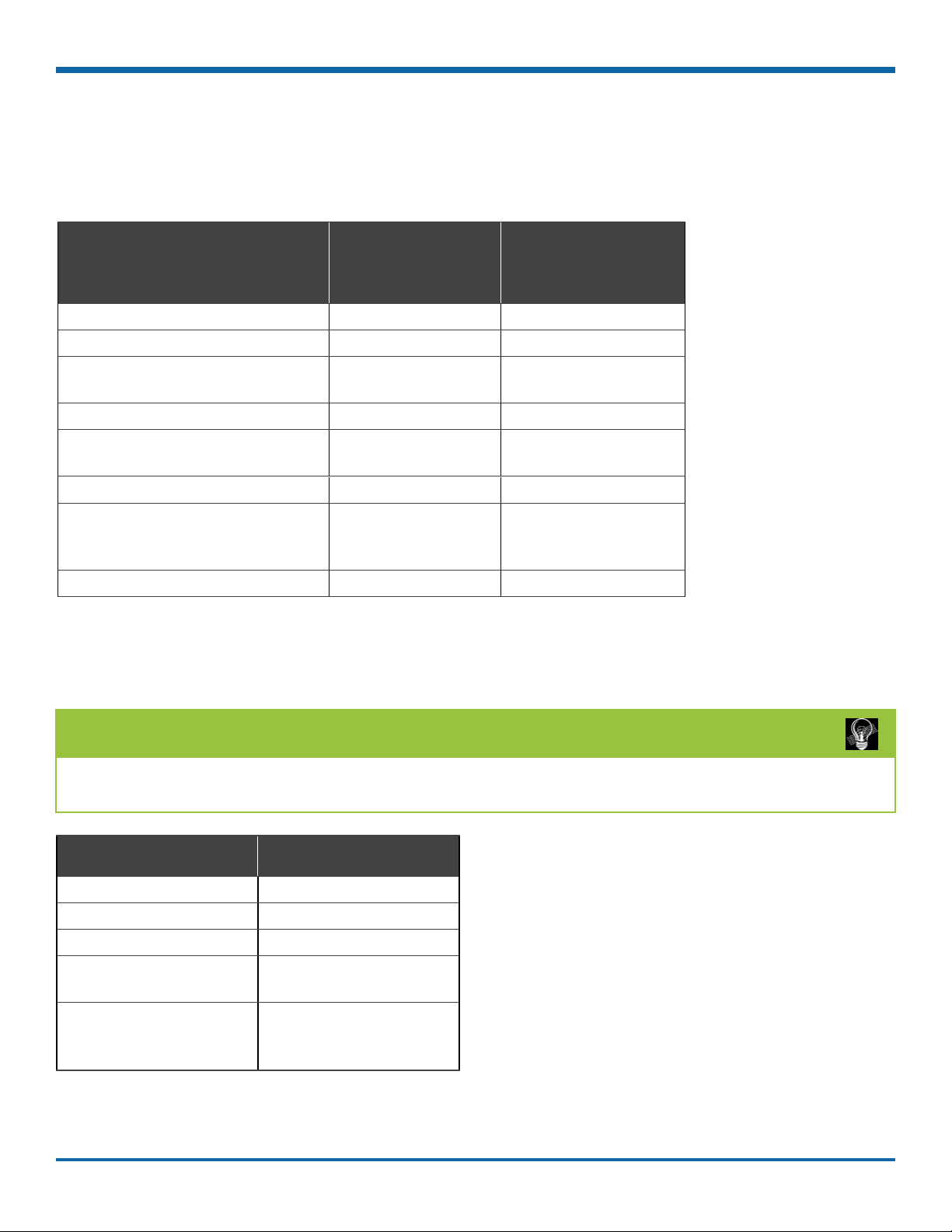
Status Details (for Installers and Technicians)
If the DVR is not recording, the status light display depends on the installed rmware, as described below. The
current rmware version appears in the top-right corner of every Conguration menu (for more information, see
"Firmware Updates" on page 13).
Potential Causes
(DVR not recording)
Status light:
Firmware v1.3.1.x or older
Status light:
Firmware v1.3.2.x or newer
HDD unlocked Blinking Blinking
HDD fault (missing, bad drive) Blinking Blinking
DVR overheated (stopped
Blinking Blinking
recording)
DVR overheated (shutdown) OFF OFF
DVR warming up (low ambient
OFF OFF
temperature)
DVR booting up Blinking Blinking, then ON
DVR in local Playback menu,
Blinking ON
TEMP power mode, or Power Off
Delay
DVR in rmware upgrade Blinking ON
RGY Indicator
On vehicles equipped with an RGY Indicator (B), colored lights provide status details:
TIP: Report a ashing green, yellow, or red RGY status light to a supervisor
The RGY status light should turn solid green approximately two minutes after the vehicle ignition is on.
Light Status
Off Powered down
Red On (not recording)
Solid green On (recording)
Flashing green On (recording, and alarm
is triggered)
Yellow On (recording, but there
is video loss from one or
more cameras)
p. 21
© Safe Fleet | May 2019 | All rights reserved
Document Number: XE-SNB2-TH6PM-R0A
TH6 Installation and Setup Guide
Tagging Video for Review
Tagging Video for Review
About
This topic explains how to ag an event, so the video footage can be located easily at a later time.
Before you begin...
In order for an operator to tag video, an Event/Diagnostic Button or Alarm Button must be installed in the vehicle.
For more information, contact Technical Support.
TIP: Automatic alarm triggers
Alarms can also tag video automatically when applied to a G Sensor threshold, excessive speed, or a GPS
fence. For more information, see "Alarms" on page 43.
To tag an event so the video is available later:
TIP: DVR is always recording!
Under normal conditions, the DVR is continuously recording when the vehicle ignition is on.
If something happens that should be agged for review, press the Event Button to ensure the event is
easy-to-nd later.
Each time you ag an event with the Event Button, the system places a special Alarm tag on the video, as well as
the date and time. Upon playback, any triggered Alarms are displayed, and the reviewer can jump directly to the
tagged sections and see the associated video (details depend on how the DVR is congured).
For more information on accessing and viewing recorded video, see the View User Guide (Safe Fleet Community
Document Library SW User Guides vMax View).
If your organization uses Commander, tagged video can be automatically downloaded and made available to
reviewers when your vehicle returns to the depot. For more information, see the Commander User Guide (Safe
Fleet Community Document Library SW User Guides vMax Commander).
p. 22
© Safe Fleet | May 2019 | All rights reserved
Document Number: XE-SNB2-TH6PM-R0A

TH6 Installation and Setup Guide
Accessing the On-screen Display
Accessing the On-screen Display
About
This topic explains how to connect a local monitor to the DVR to access conguration menus, view live camera
feeds, or search, play back, and archive video.
Video Conguration, Playback, and Archiving
Installers and System Technicians can access DVR conguration, playback and archiving features locally from
the DVR, via the On-screen Display (OSD) and a portable video monitor. For full-featured video review, searching,
and archiving, we recommend vMax View video management software on a Windows-based computer. For more
information, see the View User Guide (Safe Fleet Community Document Library SW User Guides vMax View).
Using the On-screen Display
1. Connect a portable video monitor to VIDEO OUT
on the DVR front panel.
2. Plug a USB mouse in a USB socket on the front of
the DVR.
3. Power up the DVR.
The DVR splash screen appears briey; the
system displays live camera feeds, as described
below in Live View.
4. Right-click anywhere in the OSD screen to view
the Main Menu:
• Conguration - access DVR menus to set up
the system. For more information, see "Setting
up the DVR" on page 32.
• Playback - search, play back, and archive
video directly from the DVR. For more
information, see "Working with Video" on
page 26.
Live View
During live viewing and recording, in addition to active
camera feeds, the information displayed on the OSD
includes the items shown in the image and the following
table (for how to congure camera titles, see "Camera
Settings" on page 39):
p. 23
© Safe Fleet | May 2019 | All rights reserved
Document Number: XE-SNB2-TH6PM-R0A

TH6 Installation and Setup Guide
Accessing the On-screen Display
On-Screen Display Fields
Feature Description
[MAIN_TITLE] Main title of the DVR; max. 32 characters.
[CAMERA_TITLE] Appears in the top-left corner of each viewing section (in the example, "FRONT",
"MID"....).
HD SIZE Formatted size of the DVR internal drive, in gigabytes (GB).
The second value in square brackets is the size of the SD card. "OFF" indicates the
storage media is not present.
HD USED Percentage of recorded video on the DVR hard drive. The second value in square
brackets indicates the percentage of recorded video on the SD card. "OFF" indicates
the storage media is not present.
At 100%, the message displayed depends on the Repeat Record settings in the
Recording Settings menu.
VERSION DVR rmware version.
Status DVR operational status:
- LIVE (live mode - not recording)
- PLAYBACK (DVR playing locally)
- RECORD (normal recording)
- ALARM (alarm recording)
- V.LOSS (video loss or camera signal loss)
Speed Display Vehicle speed in MPH or KPH.
Voltage System voltage from 8 to 32 VDC.
Temperature DVR temperature in degrees Fahrenheit or Celsius.
Time and Date Current/recorded time and date
GPS Coordinates If GPS is connected, the actual coordinates (latitude, longitude, and heading) appear.
If GPS is connected but the satellite signal is not being received, zeros are displayed.
AC (Alarm Count) Number of alarms triggered
Resets to 0 when DVR is restarted.
FAN Highlights to indicate trouble with the DVR fan.
GSN Highlights when external G-Sensor is connected.
IG Highlights when vehicle ignition is on.
p. 24
© Safe Fleet | May 2019 | All rights reserved
Document Number: XE-SNB2-TH6PM-R0A

TH6 Installation and Setup Guide
Using On-screen Keyboards
Using On-screen Keyboards
About
This topic describes entering text and numbers in OSD (On-screen Display) elds when accessing the DVR locally
with a mouse and monitor.
Before you begin...
A portable video monitor and a USB mouse must be connected to the DVR.
For more information, see "Accessing the On-screen Display" on page 23.
Entering Data
To enter text and numbers in OSD elds using a mouse:
1. Click in an OSD eld that accepts text or numbers
as input.
The on-screen keyboard (text or numeric, as
shown below) pops up on the screen.
2. Click text or numbers to enter values, and use the
virtual keys as required.
Cancel closes the keyboard without
saving changes.
3. When you're done, click Enter to save changes
and close the keyboard.
p. 25
© Safe Fleet | May 2019 | All rights reserved
Document Number: XE-SNB2-TH6PM-R0A

TH6 Installation and Setup Guide
Working with Video
Working with Video
About
This tutorial explains how to use the Playback menu to search, play back, and copy video directly from the DVR
hard drive.
These procedures are intended for installers and system technicians to test and conrm mobile surveillance system
functionality. For full-featured video playback, search, and archiving, we recommend the vMax View application
on a Windows-based computer. For more information, please see the View User Guide (Safe Fleet Community
Document Library SW User Guides vMax View).
Playing Back and Copying Video
To search, play back, and archive video from the
OSD (On-Screen Display) menus:
1. Connect a portable monitor and USB mouse, and
power up the DVR. For more information, see
"Accessing the On-screen Display" on page 23.
2. Right-click anywhere in the OSD view to access
the Main Menu tab.
3. Click Playback.
4. In the center of the playback view, click the Show/
Hide icon:
The Playback Toolbar appears.
5. Click icons to browse video and archive clips.
For icon descriptions, please see "Playback
Toolbar Icons" in the next section.
p. 26
© Safe Fleet | May 2019 | All rights reserved
Document Number: XE-SNB2-TH6PM-R0A

TH6 Installation and Setup Guide
Working with Video
Playback Toolbar Icons
To display the Playback Toolbar, follow steps 1 through 4 in the previous section.
Icon Name Function
A Start of clip/End of clip Sets the start of clip and the end of clip points for archiving.
B Search Searches by Date, Time, Alarm, Signals, or System Event.
C Archive Displays the Archive window to save a video clip to USB memory
device.
D Fast Rewind Reverses playback. With playback paused, each click reverses
the video by one frame.
E Play/Pause Starts/pauses playback.
F Fast Forward Fast forwards playback. With playback paused, each click
advances the video by one frame.
G Individual Camera/Multi-view Displays camera 1, 2, 3, 4, 5, 6, or multi-view.
H Audio Cycles through Audio for channel 1, 2, 3, 4, 5, or 6.
I Metadata Text Overlay Turns on text overlay: temperature, system voltage, GPS data
(if recorded), speed, date, and time. For more information, see
"Metadata Details" on page 38.
J Show/Hide Playback Tool Bar Shows/hides the playback tool bar.
Exit Closes the On-Screen Display.
p. 27
© Safe Fleet | May 2019 | All rights reserved
Document Number: XE-SNB2-TH6PM-R0A

TH6 Installation and Setup Guide
Searching Video
The DVR includes a simple, powerful search feature
that quickly nds recorded information by Date and
Time, Alarm, Signals, or System Events.
To view the Search menu:
1. From the Playback Toolbar, click the Search icon:
The Search tab appears (options displayed
depend on the Search Only pull-down
menu selection).
2. Use the Start/End Date and Time elds to set the
desired period to search.
For instructions on how to enter numbers into
the Date and Time elds, see "Using On-screen
Keyboards" on page 25.
Working with Video
3. If desired, use the Search Only pull-down and
sub-menus to specify Alarms, Signals, or System
Events to search.
4. Click Search.
• If Search Only is set to Time: Playback starts
from the specied time and date (if the video
exists on the hard drive).
• If you selected Alarms, Signals, or System
Events:
The DVR retrieves a list of recorded video
segments containing the specied event type.
Select an item from the list, then click Play
to view the video captured when the event
occurred.
p. 28
© Safe Fleet | May 2019 | All rights reserved
Document Number: XE-SNB2-TH6PM-R0A
TH6 Installation and Setup Guide
Health Check
Health Check
About
This topic describes the Health Check tab. It provides information on hard drive temperature, hard drive operational
hours, Ethernet connections, and general DVR health.
Before you begin...
Power up the DVR with a monitor and USB mouse connected, then right-click in Live view and select Conguration.
For more information, see "Accessing the On-screen Display" on page 23.
To display Health Check information:
Select Title/Display Health Check.
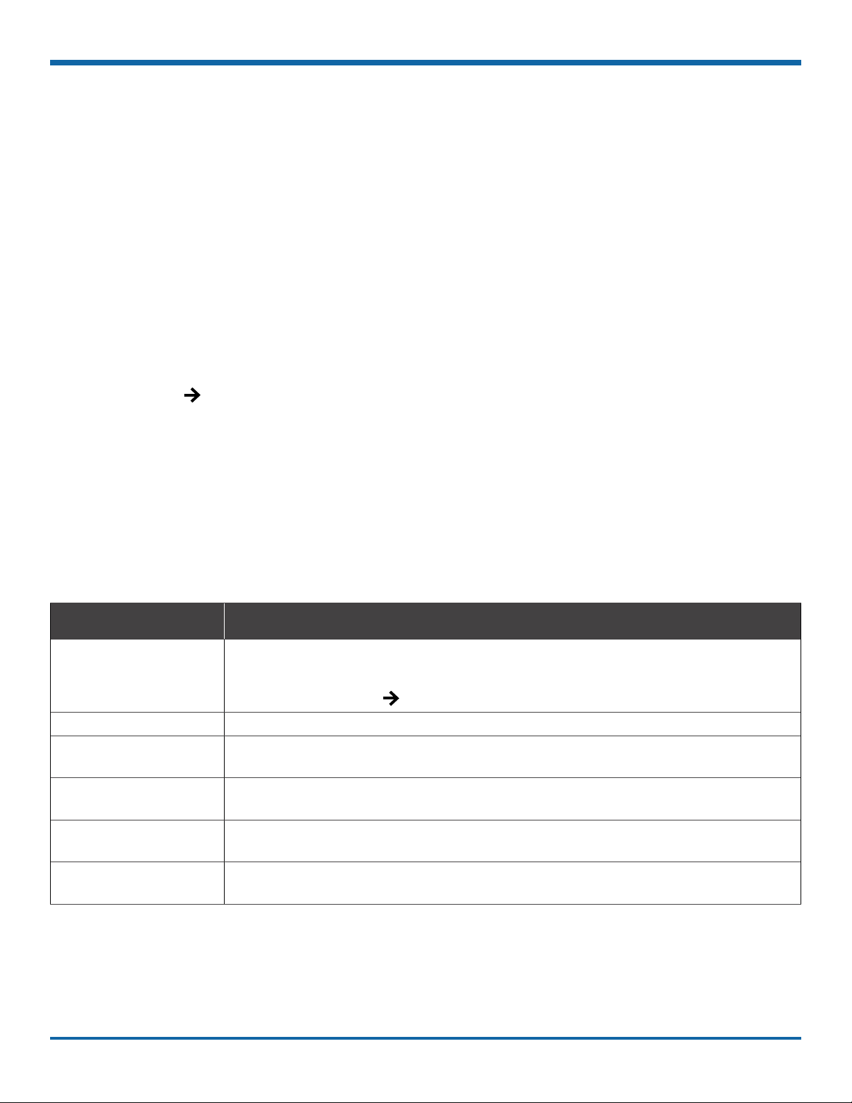
Information Display
Menu Item Description
Hard Drive Temperature Current temperature inside the drive.
To choose whether this value displays in Fahrenheit (USA) or Celsius (Canada), use
the Titles and Display Internal Temperature Units setting.
Hard Drive Hours The number of hours the drive has been powered on since it was manufactured.
General Health Result of the drive subsystem self-check: green indicates normal operating status,
while red means a drive failure was detected.
LAN Front Connectivity indicator: green when a cable is connected from the DVR's front LAN port
to an operational network device; otherwise red.
Modem Connectivity indicator: green when a cable is connected from the DVR's rear Modem
port to an operational network device; otherwise red.
WiFi Connectivity indicator: green when a cable is connected from the DVR's rear WiFi port
to an operational network device; otherwise red.
p. 29
© Safe Fleet | May 2019 | All rights reserved
Document Number: XE-SNB2-TH6PM-R0A

TH6 Installation and Setup Guide
Health Check
— this page intentionally left blank —
p. 30
© Safe Fleet | May 2019 | All rights reserved
Document Number: XE-SNB2-TH6PM-R0A

TH6 Installation and Setup Guide
Basic Conguration
Setting up the DVR ..................................................................................................................................... 32
DVR Menu Access .................................................................................................................32
Basic DVR Conguration .......................................................................................................33
Time/Date Menu ...........................................................................................................................................34
Time/Date Tab ........................................................................................................................34
Time and Date Menu Options ................................................................................................35
Title/Display Menu .......................................................................................................................................36
Titles and Display Tab ............................................................................................................36
Title/Display Menu Options ....................................................................................................37
Metadata Details ....................................................................................................................38
Camera Settings ..........................................................................................................................................39
Basic Conguration
Camera Tab ...........................................................................................................................39
Camera Settings - Menu Options ..........................................................................................40
Signals...........................................................................................................................................................41
Signals Tab ............................................................................................................................41
Signals Tab - Menu Options ...................................................................................................42
Alarms ...........................................................................................................................................................43
Alarm Settings .......................................................................................................................43
Alarm Settings - Menu Options ..............................................................................................44
p. 31
© Safe Fleet | May 2019 | All rights reserved
Document Number: XE-SNB2-TH6PM-R0A

TH6 Installation and Setup Guide
Setting up the DVR
Setting up the DVR
About
This topic describes procedures for conguring the DVR, including system settings, cameras/recording,
alarms, and network details (if applicable).
Before you begin...
The unit should be installed, including power and cabling.
For more information, see "Installation" on page 5 .
DVR Menu Access
You can congure the DVR with its local on-screen menus using a monitor and mouse, or through a Web browser
on a connected laptop. These settings can also be accessed remotely over a wireless network.
Local access with On-screen Display (OSD) menus:
Connect a portable monitor to the VIDEO OUT RCA jack on the DVR front panel and plug a mouse into the USB
port to work with conguration settings.
For more information, see "Accessing the On-screen Display" on page 23.
To set or change a password, right-click in Live view, then choose the Conguration System Password options.
Local access with vMax Web menus:
Congure the network connection on a PC, and connect to the DVR with an RJ-45 Ethernet cable. You can then
use vMax Web to congure the DVR via Internet Explorer.
The default network settings only allow connecting the DVR to a laptop using an Ethernet cable.
For remote network access, consult your IT staff or Technical Support to congure the DVR to be on the same
subnet as the laptop.
Remote access with vMax Web menus:
If you have Smart Reach wireless access, you can also access the DVR remotely using vMax Web via Internet
Explorer. Contact the Technical Support team for more information.
p. 32
© Safe Fleet | May 2019 | All rights reserved
Document Number: XE-SNB2-TH6PM-R0A

TH6 Installation and Setup Guide
Setting up the DVR
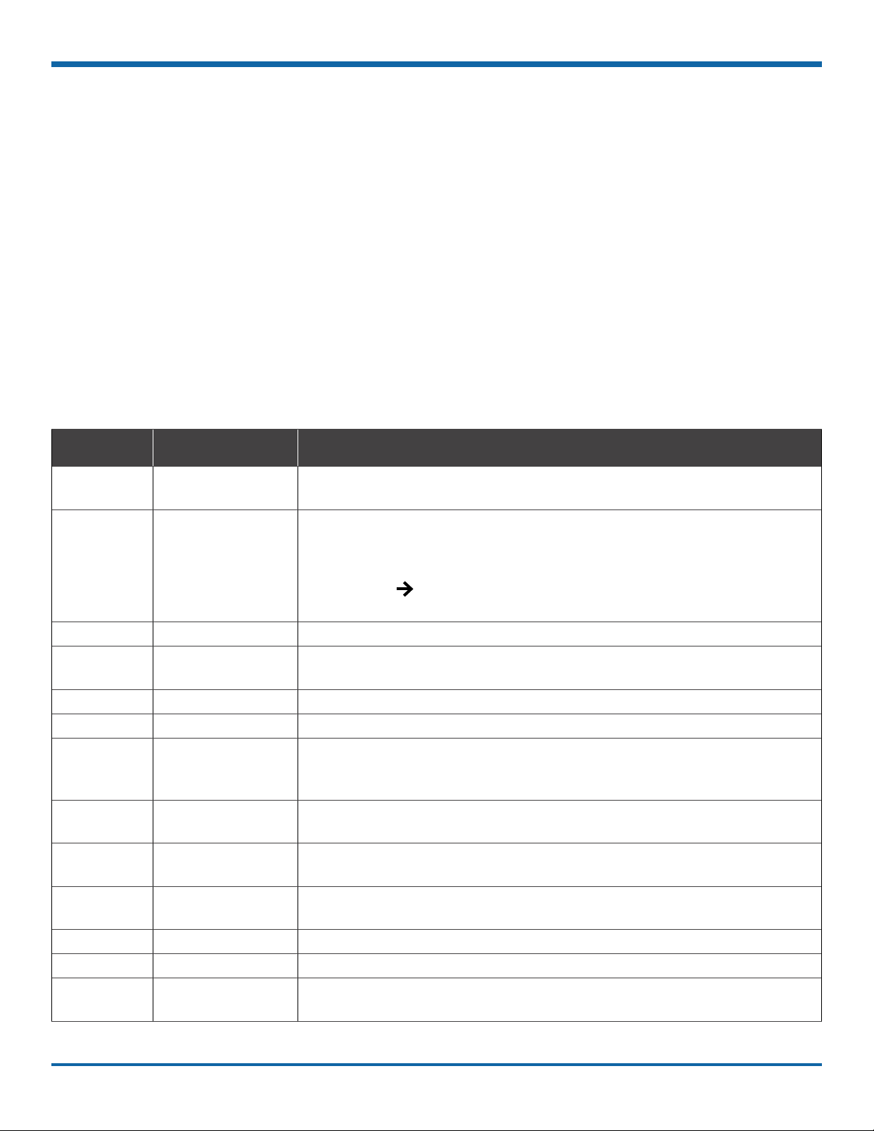
Basic DVR Conguration
The DVR menu defaults cover most operational settings, but some basic customer and region-specic settings need to be
congured for the DVR to operate optimally:
For more
Menu Names Required Settings
information:
Time and Date,
DST Settings
Titles/Display Enter the vehicle number in Main Title, and choose
Title/Display Monitor Settings
Record Set the Record Delay Off to 15-20 minutes for post
Record Camera
Alarms and Signals Alarms
Select display formats.
Enter the current time and date, including Daylight
Saving if applicable.
Select the Time Zone.
If GPS is installed, set GPS Time Sync ON to detect
time and vehicle location.
the information that displays as text when video
appears.
If a Rear Vision Camera is installed, select monitor
output settings.
trip check.
If Wi-Fi is used, set the Power Delay Off to 2 hours for
archive download.
Turn off any unused camera channels, to avoid
VLOSS events.
Congure each alarm depending on source (Signals,
Speed, G Sensor, GPS Fence, Wake).
See page 34
See page 36
See page 66
See page 46
See page 39
See page 43
Alarms and Signals Signals
Alarms and Signals Speed
Alarms and Signals G Sensor
Network If Wi-Fi network is used, set addresses as instructed
System Select the audio channel to output from the DVR
System Program Update
p. 33
Congure which signals will trigger alarms. Excessive
speed and G Sensor readings can be set as signal
outputs.
If the DVR is used in Canadian eets, select KPH
speed units.
If a G Sensor is installed, Calibrate. See page 54
by a network administrator.
audio RCA socket.
If a Diagnostic Indicator or RGY Illuminator is
installed, select it here.
Upload DVR conguration if necessary.
Format the hard drive after all settings have
been made.
© Safe Fleet | May 2019 | All rights reserved
Document Number: XE-SNB2-TH6PM-R0A
See page 41
See page 57
See page 48
See page 62
See page 64

TH6 Installation and Setup Guide
i
Time/Date Menu
Time/Date Menu
About
This topic describes the Time and Date conguration tab settings, including time zone, daylight savings (if required),
and optionally synchronizing the DVR date and time with GPS satellites.
Before you begin...
Power up the DVR with a monitor and USB mouse connected, then right-click in Live view and select
Conguration. For more information, see "Accessing the On-screen Display" on page 23
Time/Date Tab
NOTE: Time Zone
Ensure these settings are correct for the customer location/time zone – the DVR date and time are used
as an index for searching, archiving, and downloading video, and appear during playback.
To update settings:
1. Select Time/Date to display the tab.
2. Select elds and/or use menus to make your
changes (menu options are described later in this
topic).
For details on entering data with the mouse, see
"Using On-screen Keyboards" on page 25
3. Click Back to save the settings and return to the
Conguration menu.
p. 34
© Safe Fleet | May 2019 | All rights reserved
Document Number: XE-SNB2-TH6PM-R0A

TH6 Installation and Setup Guide
Time and Date Menu Options
Menu Item Description Value [Default]
Time/Date Menu
Daylight Saving Leave ON and at default dates unless in an area that does not use
daylight savings (e.g. Arizona, Saskatchewan).
Click DST Settings and ensure the Start/End dates and times apply
to your location.
Time Zone Select your local time zone. [UTC-05 Eastern Standard
Time Format Choose 12 or 24-hour display. [12 hour]:
Time Enter the correct time.
Date Format Select the preferred date format. [MM/DD/YYYY]
Date Set the date for the DVR.
GPS Time Sync If GPS is installed, set this ON to have the system time
automatically updated when satellites are detected.
[ON]
Time]
12:00 am to 11:59 pm
24 hour:
00:00 to 23:59
YYYY/MM/DD
DD/MM/YYYY
[OFF]
p. 35
© Safe Fleet | May 2019 | All rights reserved
Document Number: XE-SNB2-TH6PM-R0A
TH6 Installation and Setup Guide
Title/Display Menu
Title/Display Menu
About
This topic describes setting up information to display as text when viewing live or recorded video, including the Main
Title (generally a vehicle/bus number to identify the video source), as well as the time/date and various system
status details.
Before you begin...
Power up the DVR with a monitor and USB mouse connected, then right-click in Live view and select Conguration.
For more information, see "Accessing the On-screen Display" on page 23.
Titles and Display Tab
TIP: Changing the default display
All options are set to display by default. You can turn OFF items that are not of interest so the related text will not appear.
1. Select Title/Display to open the tab.
2. Enter the bus number in the Main Title eld (if it
is not already there). For more information about
using the On-screen keyboard, see "Using Onscreen Keyboards" on page 25
3. Choose the desired display settings, as described
in "Menu Options", below.
For information about display items, see "Metadata
Details" on page 38.
p. 36
© Safe Fleet | May 2019 | All rights reserved
Document Number: XE-SNB2-TH6PM-R0A
TH6 Installation and Setup Guide
Title/Display Menu
Title/Display Menu Options
Menu Item Description Value [Default]
Main Title Enter the bus number. MAIN_TITLE
Titles Display Display/hide Main Title and Camera Titles [ON], OFF
Time/Date Display Display/hide time and date [ON], OFF
Record Status Display Display/hide DVR recording status (LIVE=showing camera feeds,
RECORD=storing video, V.LOSS=video loss).
System Data Display Display/hide DVR system Metadata: HDD Size, % Full HDD,
Voltage, Firmware Version, Fan Failure, and Internal Temperature.
For more information, see "Metadata Details" on page 38 .
Metadata Display Display/hide DVR Metadata: Signals, GPS, Speed, Ignition State,
G-Sensor, and Alarm Count.
For more information, "Metadata Details" on page 38.
Internal Temperature Units If Metadata Display is ON, display the ambient temperature
inside the DVR in degrees. Select F (Fahrenheit) in the USA or C
(Celsius) in Canada.
[ON], OFF
[ON], OFF
[ON], OFF
[F], C
p. 37
© Safe Fleet | May 2019 | All rights reserved
Document Number: XE-SNB2-TH6PM-R0A
TH6 Installation and Setup Guide
Metadata Details
Reference Data Item Description
Title/Display Menu
A HD Size Internal drive size (GB). The second value in square brackets displays SD
card size in GB. "OFF" appears when storage media is not present.
B HD Used Percentage of internal drive space used. The second value in square
brackets displays percentage of drive spaced used on the SD card. "OFF"
appears when storage media is not present.
If the Record Repeat Record setting is ON, displays "Repeating". For
more information, see "Recording Settings" on page 46
C Version Firmware version.
D Status DVR status: (LIVE=showing camera feeds, RECORD=storing video,
V.LOSS=video loss).
E Speed Vehicle speed.
F Voltage System input voltage.
G Temperature Ambient temperature inside the DVR (F=Fahrenheit, C=Celsius).
H Signals When a signal activates, the Label is displayed. For more information, see
"Signals" on page 41.
I GPS Coordinates Latitude/longitude, and elevation. If GPS is connected but satellite signals
are not being received, zeros appear.
J Alarm Count (AC#) The current number (1-9) of triggered Alarms. The value resets to 0 when the
DVR restarts. For more information, see "Alarms" on page 43 .
K Ignition (IG) Vehicle ignition state (highlighted=ignition on, dimmed=off).
L Fan Fan failure notication (highlighted=failure, dimmed=normal)
M G Sensor (GSN) G Sensor threshold incident (highlighted=threshold exceeded). For more
information, see "G Sensor - Menu Options" on page 56.
p. 38
© Safe Fleet | May 2019 | All rights reserved
Document Number: XE-SNB2-TH6PM-R0A

TH6 Installation and Setup Guide
!
Camera Settings
Camera Settings
About
This topic describes how to set up camera recording parameters.
Before you begin...
Power up the DVR with a monitor and USB mouse connected, then right-click in Live view and select
Conguration. For more information, see "Accessing the On-screen Display" on page 23.
Camera Tab
IMPORTANT: Turn off unused camera channels
When a DVR is installed with less than the full number of cameras connected (e.g., for a TH6 DVR, less than
6 cameras), disable the unused camera input settings to prevent the DVR from generating Video Loss (VLoss)
events for those camera inputs. In the DVR Conguration menus, disable settings for unused camera inputs as
follows:
• Record FPS OFF
• Record Camera Audio OFF (to save disk space)
• Alarm/Signal Alarms FPS OFF
To congure cameras:
1. Select Record Camera to open the tab.
2. Set up the cameras. For details, see Menu
Options, below.
3. Click Back to save Camera settings, then click
Back again to return to the Conguration menu.
TIP: DVR Recording Limitation
TH6 DVRs cannot record 1080p video at 30 frames per second.
p. 39
© Safe Fleet | May 2019 | All rights reserved
Document Number: XE-SNB2-TH6PM-R0A

TH6 Installation and Setup Guide
Camera Settings
Camera Settings - Menu Options
Menu Item Description Value [Default]
Title For each camera, enter a name that describes the view it is
recording. For example: "Front", "Step", "Mid", "Rear", "Stop Arm".
For instructions on how to enter text with the mouse, see "Using On-screen
Keyboards" on page 25.
Camera titles display in live views and during playback. For more information,
"Metadata Details" on page 38.
FPS (channel speed) Leave channel speed at the default setting unless you have
special requirements.
This sets the recorded frame rate, per second.
Quality Leave channel quality at the default setting unless you have
special requirements.
Setting 1 is the lowest quality, and 4 is the highest. Increased quality involves
greater storage requirements. The DVR uses compression technology to extend the
amount of video (recording time) that can be stored.
Resolution Leave channel resolution at the default setting unless you have
special requirements.
This sets the recording resolution (in pixels). Higher resolution reduces the amount
of video (recording time) that can be stored.
[Channel01]...
[Channel06]
[15 fps.], OFF, 1 fps,
5 fps, 7 fps, 10 fps,
15 fps, 20 fps, 30 fps*
* TH6 DVRs do not
support 1080p @
30fps.
[3], 1, 2, 3, 4
SD source:
[720x480],
720x240, 360x240
1MP source:
[1280x720],
640x360, 320x180
2MP source:
[1920x1080]
Audio Leave ON unless the camera is mounted on the exterior of the
vehicle, or if you have special requirements.
Setting Audio ON enables audio recording for the input channel. Turn OFF Audio for
unused camera channels.
Apply CH1 to All Click to apply settings selected for Channel 1 to all cameras. n/a
Camera Advanced Click to access the Camera Advanced tab and adjust settings for each camera with
CoC (Control over Coax).
p. 40
© Safe Fleet | May 2019 | All rights reserved
Document Number: XE-SNB2-TH6PM-R0A
[ON], OFF
n/a

TH6 Installation and Setup Guide
Signals
Signals
About
This topic describes how to congure signals and the actions they generate. The DVR supports 10 independent
signals. The rst ve are dedicated input wire (signal harness) connections: LT (left turn signal), STP (stop), BRK
(brake), WRN (warning lights), and RT (right turn signal). The last ve can be set for other functions, such as an
excessive speed event or when the installed G-sensor exceeds a threshold.
Before you begin...
Power up the DVR with a monitor and USB mouse connected, then right-click in Live view and select Conguration.
For more information, see "Accessing the On-screen Display" on page 23.
Signals Tab
TIP: Signal Labels and Searching for Events
When a signal is activated, the associated 3-character label appears on-screen during video playback.
For example, "BRK" appears when the brake pedal is applied. For more information, see "Metadata Details" on
page 38.
It is important to understand that you can also search video for signal events. For example, you can nd
every instance when the warning lights were activated.
For more information, see the View User Guide (Safe Fleet Community Document Library SW User Guides
vMax View) and "Working with Video" on page 26.
1. Select Alarm/Signal Signals to open the tab.
2. Congure signals as required.
Each signal displays its status (label) when active,
and can also trigger an Alarm. For details, see
Menu Options, below.
3. Click Back to save settings, then click Back again
to return to the Conguration menu.
p. 41
© Safe Fleet | May 2019 | All rights reserved
Document Number: XE-SNB2-TH6PM-R0A

TH6 Installation and Setup Guide
Signals Tab - Menu Options
Menu Item Description Value [Default]
Signals
Signal Signals 1 through 5 are hardwired inputs, received through the
signal harness (LT/left turn signal - black wire, STP/stop - green
wire, BRK/brake - red wire, WRN/warning lights - brown wire,
and RT/right turn signal - white wire). When these triggers are
active, they generate signals and display associated labels
during video playback.
Signals 6 through 10 can be user-dened.
Label You can edit the on-screen display text label (maximum 3
characters) to describe each signal as desired.
For instructions on using the mouse to enter data, see "Using
On-screen Keyboards" on page 25.
Level Control how the signal senses activation: choose Active H (high)
if the circuit rests at 0 VDC and goes to 12 VDC when active;
choose Active L (low) if the circuit rests at 12 VDC and drops to 0
when active.
Alarm Select the alarm number if the signal is also used to trigger an
alarm. The alarm's input must also be set up in the Alarms menu.
For more information, see "Alarms" on page 43
Note: assigning alarms to the default signals 1 through 5 is
generally not recommended, since these would be continually
triggered by normal vehicle operation.
n/a
Labels 1 through 5:
[LT], [STP], [BRK], [WRN], [RT].
Labels 6 through 10:
[S06], [S07], [S08], [S09], [S10]
[Active H], Active L
[OFF], ALM1, ALM2, ALM3, ALM4
p. 42
© Safe Fleet | May 2019 | All rights reserved
Document Number: XE-SNB2-TH6PM-R0A

TH6 Installation and Setup Guide
!
Alarms
Alarms
About
This topic describes how alarms work and how to congure them. Triggered alarms create searchable ags in the
recorded video, making it easy to locate alarm events and associated Metadata later (for details, see the View User
Guide (Safe Fleet Community Document Library SW User Guides vMax View). You can also tell the system to
switch to higher recording quality settings when an alarm is triggered - for example, to help identify people or license
plates when reviewing video of the event. If the system is wirelessly enabled with Commander, agged video can
be automatically downloaded to your network (for more information, see the Commander User Guide (Safe Fleet
Community Document Library SW User Guides vMax Commander).
Before you begin...
Power up the DVR with a monitor and USB mouse connected, then right-click in Live view and select Conguration.
For more information, see "Accessing the On-screen Display" on page 23.
Alarm Settings
The DVR supports 4 independent Alarms. By default, Alarm 1 is connected to the optional Event/Diagnostic
button installed in the vehicle, for use by the operator (for more information, see "Tagging Video for Review" on
page 22). Alarms 2-4 can be triggered automatically by vehicle speed, a G-sensor threshold, GPS fencing, or
when a Signal is activated.
To congure Alarms:
1. Select Alarm/Signal Alarms to open the tab.
2. Congure Alarm settings as required. For details,
see Menu Options, below.
3. Click Back to save settings, then click Back again
to return to the Conguration menu.
IMPORTANT: Turn off FPS for unused channels
Set FPS (Frames per Second) OFF for unused channels to avoid DVR video loss events.
TIP: Higher recording quality settings for Alarm events
Select higher speed (FPS), Quality, and Resolution in Alarm Settings to increase video quality for a short
duration to record an alarm event.
Higher quality video involves greater storage requirements, which reduces the amount of video you can store
before it is overwritten. Therefore, a DVR usually records in a mode that conserves storage space.
p. 43
© Safe Fleet | May 2019 | All rights reserved
Document Number: XE-SNB2-TH6PM-R0A

TH6 Installation and Setup Guide
Alarm Settings - Menu Options
Menu Item Description Value [Default]
Alarms
Alarm Click to display settings for the selected Alarm.
By default, Alarm1 is connected to the DVR Event/Diagnostic
button. Alarms 2-4 can come from Signals, GPS geo-fencing,
G-sensor, or Excessive Speed.
Duration The length of time after the alarm has been triggered that
agged video is recorded at the alarm speed (FPS), quality,
and resolution settings described below.
Input Applies to Alarm 1 only. When triggered with the Event/
Diagnostic button, use the default setting.
Control how the alarm input senses activation: choose "N.O."
(Normally Open) or N.C. (Normally Closed).
FPS For each channel, the recording speed in FPS (Frames Per
Second) used when the alarm is triggered.
If the DVR normally records at a mid-range or low FPS to
conserve storage space, set a higher FPS value to increase
video quality for a short duration to record an alarm event.
Quality For each channel, the recording quality used when the
alarm is triggered.
The DVR offers a range of quality settings, from 1 (low) to 4 (high).
[Alarm1], Alarm2, Alarm3, Alarm4
0, 5, 10, [30] sec., 1, 3, 5, 10, 15, 20,
30, 45 min.
[N.O.],
N.C.
OFF, 1, 5, 7, 10, 15, 20,
[30] FPS
1, 2, [3], 4
Resolution For each channel, the recording resolution (in pixels)
used when the alarm is triggered. The higher the recording
resolution, the better the picture looks, but the shorter the
recording time on a hard drive.
Three options are provided. Details depend on the camera
connected to the channel (HD 1080p, HD 720p, or Standard
Denition). The highest supported resolution is the default, and
two lower-quality options are available.
[1920 x 1080]...
[1280 x 720]...
[720 x 480]...
p. 44
© Safe Fleet | May 2019 | All rights reserved
Document Number: XE-SNB2-TH6PM-R0A

TH6 Installation and Setup Guide
Advanced Conguration
Advanced Conguration
Recording Settings ........................................................................................................ 46
Network Settings ...........................................................................................................48
Advanced Network Settings .........................................................................................50
VMS Servers .................................................................................................................52
G Sensor .......................................................................................................................54
Speed Settings .............................................................................................................. 57
GPS Fencing ................................................................................................................. 58
User Levels ....................................................................................................................60
System Settings ............................................................................................................62
Program Update ............................................................................................................ 64
Monitor Settings ............................................................................................................66
Wake on Input, Digital Output ....................................................................................... 68
Customer Service ..........................................................................................................72
Product Information ....................................................................................................... 72
Warranty ........................................................................................................................72
p. 45
© Safe Fleet | May 2019 | All rights reserved
Document Number: XE-SNB2-TH6PM-R0A

TH6 Installation and Setup Guide
Recording Settings
Recording Settings
About
This topic describes recording and power settings, including video storage management and options for DVR
behavior when the vehicle ignition is turned on/shut down.
Before you begin...
Power up the DVR with a monitor and USB mouse connected, then right-click in Live view and select Conguration.
For more information, see "Accessing the On-screen Display" on page 23.
Record Tab
1. Select Record to open the tab.
2. Set the record and power delay timers.
For details, see Menu Options, below.
3. Click Back to save the settings, or click Camera to
congure resolution, recording speed/quality, and
other camera options.
p. 46
© Safe Fleet | May 2019 | All rights reserved
Document Number: XE-SNB2-TH6PM-R0A
TH6 Installation and Setup Guide
Recording Settings
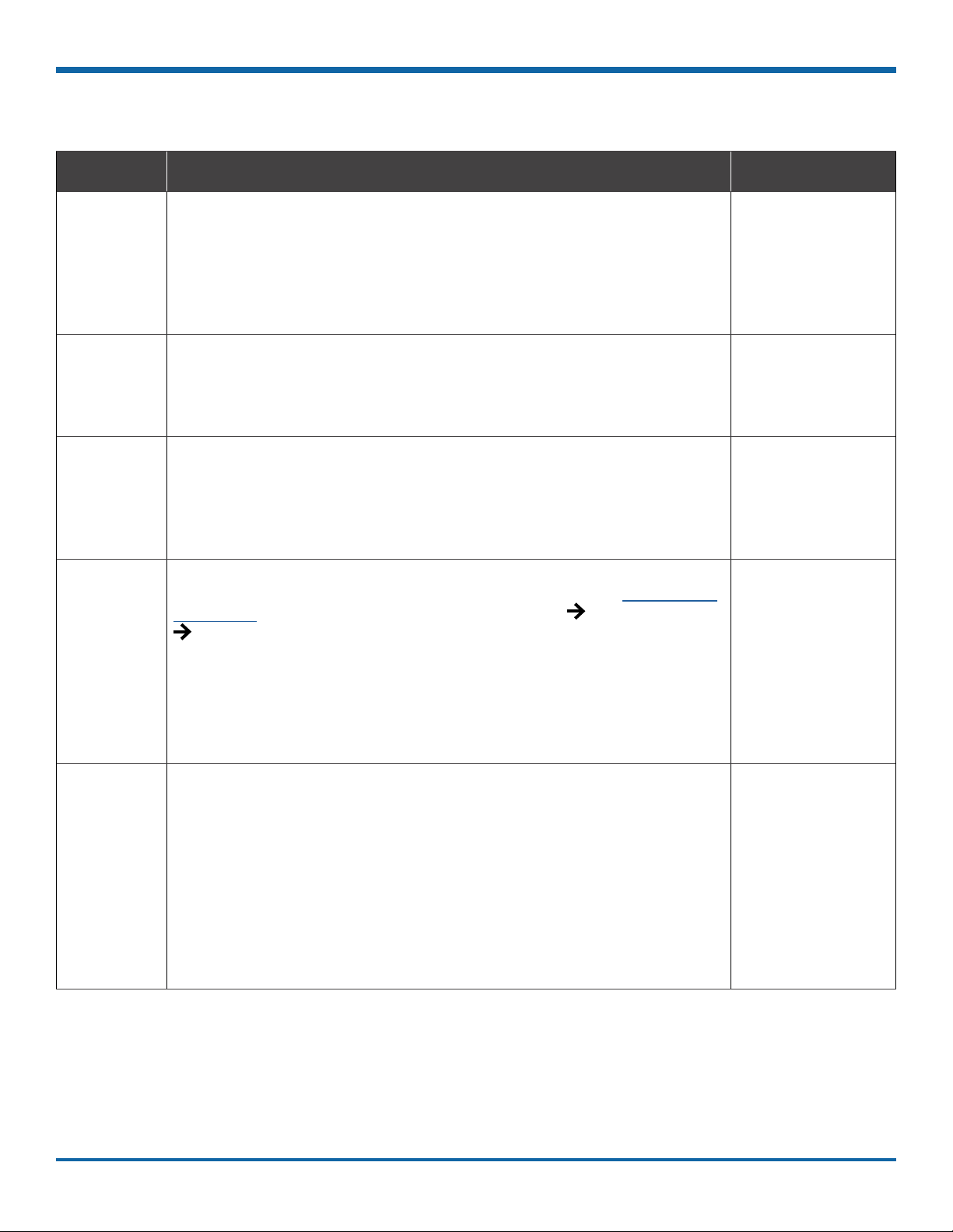
Recording Settings - Menu Options
Menu Item Description Value [Default]
Repeat
Record
Record-On
Delay Time
Record-Off
Delay Time
Power-Off
Delay Time
Leave this setting at the default [ON] for the storage media to loop,
and record over the oldest video when it becomes full (the "HD Used"
Metadata item displays "Repeating" - for more information see "Metadata
Details" on page 38).
When set to OFF, the DVR stops recording when storage is full ("HD Used"
displays 100%).
Leave at default to let the voltage settle after the vehicle starts up to
prevent voltage drops affecting the DVR.
Enables a time delay after the vehicle ignition is turned on until the
DVR starts.
To keep the DVR and cameras on after the ignition turns off (e.g. to
record the post-trip check), set this to 10 or 20 min.
Enables a time delay to continue recording after the ignition signal to the
DVR is turned off. The power output connector on the DVR rear panel
remains active during this time.
If the system is not using Wi-Fi, use the default setting. If Wi-Fi is
used, set to 2 hours or more. For more information, see the Commander
User Guide (Safe Fleet Community Document Library SW User Guides
vMax Commander).
This sets the time delay from the record delay until power is shut off. The
delay begins after "Record Delay Off" time ends. During this time, cameras
are turned off and recording is stopped. However, the control connector
on the DVR rear panel remains active to allow peripherals such as SmartReach to be powered up during the power delay time.
[ON], OFF
[15 sec.], 30 sec.,
1 min., 5 min.,
10 min., 20 min.,
30 min.
[15 sec.], 30 sec.,
1 min., 5 min.,
10 min., 20 min.,
30 min.
[15 sec.], 0 sec.,
30 sec., 1 min.,
5 min., 10 min.,
20 min., 30 min., 45
min., 1 hr., 2 hr., 4
hr.
Record2 Leave at the default setting unless instructed otherwise.
Unless set to OFF, the DVR records a low resolution second video stream
at the selected frame rate. The DVR can record video in two streams:
one at high resolution for full, detailed event information, and the other
(Record2) at lower resolution for fast downloading or real-time viewing
over a low bandwidth network such as a cellular link. In the event of an
emergency, if the system is congured with Smart-Reach cellular hardware
and a cellular plan, Record2 allows quick access to video online. Use the
Record2 setting to specify a lower per second recording (frame rate) for the
second video stream.
p. 47
[5 fps], OFF, 1 fps,
2 fps, 3 fps, 4 fps,
5 fps
© Safe Fleet | May 2019 | All rights reserved
Document Number: XE-SNB2-TH6PM-R0A

TH6 Installation and Setup Guide
i
Network Settings
Network Settings
About
This topic describes the communication parameters required to use Smart-Reach Mobile wireless bridge equipment
and Ethernet to connect the DVR to computers and networks.
More information on related products and features is available from:
Commander User Guide (Safe Fleet Community Document Library SW User Guides vMax Commander)
View User Guide (Safe Fleet Community Document Library SW User Guides vMax View)
Before you begin...
Power up the DVR with a monitor and USB mouse connected, then right-click in Live view and select Conguration.
For more information, see "Accessing the On-screen Display" on page 23.
Network Tab
NOTE: Conguring Network Settings and Advanced Network Settings
A qualied IT administrator is required to provide information and congure Network Settings and
Advanced Network settings.
These tasks should only be performed by engineering services or the eet system administrator.
• Each host (computer) connected to the network must have a unique IP address.
• If the DVR is attached to a WiFi bridge, change these settings to those supplied by the system
administrator.
• If the IP information is changed and saved in a conguration le for upload to other DVRs, their settings
must also be updated. For more information, see TH Conguration: Copying DVR Conguration.
Contact Technical Support to assign an IP address or reset the Smart-Reach Mobile wireless bridge, or for
more information.
To congure Network Settings:
1. Select Network to open the tab.
2. Congure settings as required.
For details, see Menu Options, below.
3. Click Back to save changes and return to the
Conguration menu.
p. 48
© Safe Fleet | May 2019 | All rights reserved
Document Number: XE-SNB2-TH6PM-R0A
TH6 Installation and Setup Guide
Network Settings
Network Settings - Menu Options
Menu Item Description Value [Default]
Setting Type Contact your administrator to congure the setting type and IP address
OFF disables all Ethernet capability.
Static IP is a permanent address on the network, assigned by the network
administrator. DHCP (Dynamic Host conguration Protocol) automates the
assignment of IP addresses in a network.
If DHCP is used, the subnet mask, default gateway, and DNS server are
congured automatically, and only the HTTP Port eld is editable.
IP Address Enter the DVR IP Address, as determined by a qualied network expert. [169.254.1.1]
Subnet Mask Enter the Subnet Mask, as determined by a qualied network expert. [255.255.0.0]
LAN
Gateway
DNS Server Uses an IP address composed of four octets, separated by decimals. [0,0,0,0]
MAC
Address
HTTP Port Typically, leave the HTTP Port set to 80, unless otherwise instructed by IT
Gateway address uniquely identies a host or computer on the LAN,
which connects the subnet to other networks. Enter the LAN Gateway, as
determined by a qualied network expert.
MAC (Media Access Control) is the DVR's unique hardware number. Fixed
personnel.
[Static IP], OFF,
DHCP
[169.254.1.1]
80
p. 49
© Safe Fleet | May 2019 | All rights reserved
Document Number: XE-SNB2-TH6PM-R0A

TH6 Installation and Setup Guide
i
Advanced Network Settings
Advanced Network Settings
About
This topic describes the communication parameters required to enable the DVR for vMax Live Plus, a Web-based
solution providing GPS for Automatic Vehicle Location and telemetry data for monitoring vehicle sensors.
For more information, see the View User Guide (Safe Fleet Community Document Library SW User Guides
vMax View).
Before you begin...
Power up the DVR with a monitor and USB mouse connected, then right-click in Live view and select Conguration.
For more information, see "Accessing the On-screen Display" on page 23.
Advanced Settings Tab (vMax Live Plus)
Use this tab to set up the DVR to connect with vMax Live Plus via a cellular modem. For more information, see the
vMax Live Plus documentation (Safe Fleet Community Document Library SW User Guides vMax Live Plus).
NOTE: Qualied IT Administrator Required
A qualied IT administrator is required to perform network conguration, including assignment of IP
addresses.
A cellular modem or gateway must also be installed and congured.
Contact Technical Support for more information.
To congure Advanced Network Settings:
1. Select Network Advanced to open the tab.
2. Congure settings as required.
For details, see Menu Options, below.
3. Click Back to save changes, then click Back again
to return to the Conguration menu.
p. 50
© Safe Fleet | May 2019 | All rights reserved
Document Number: XE-SNB2-TH6PM-R0A
TH6 Installation and Setup Guide
Advanced Network Settings
Advanced Network Settings - Menu Options
Menu Item Description Value [Default]
Integrated
VML (vMax
Live)
LAN Range If the customer network is outside of the DVR network: set the customer
LAN Subnet
Mask
iVML IP
Address
iVML Subnet
Mask
Default
Gateway
Set ON to enable the integrated VML feature. OFF disables the integrated
VML feature.
network’s LAN range as determined by a qualied network expert.
Note: There must be a value in this eld. If not used, enter a dummy IP
address such as 10.10.0.0.
Set the LAN subnet mask used for the LAN Gateway Destination range as
determined by a qualied network expert. Use a value between 0 and 32.
Enter the iVML IP Address as determined by a qualied network expert. [172.30.2.2]
Set the subnet mask for the iVML IP Address as determined by a qualied
network expert. Use a value between 0 and 32.
Enter the Default Gateway IP address for communicating with the cellular
modem, as determined by a qualied network expert.
[OFF], ON
[0.0.0.0]
[16]
[24]
[172.30.2.1]
p. 51
© Safe Fleet | May 2019 | All rights reserved
Document Number: XE-SNB2-TH6PM-R0A

TH6 Installation and Setup Guide
VMS Servers
VMS Servers
About
This topic describes setting up communication parameters required to enable the DVR for Commander software.
Commander remotely schedules and displays downloaded alarm video archives, tracks vehicles, and runs reports
on eet activity.
For more information, see the Commander User Guide (Safe Fleet Community Document Library SW User
Guides vMax Commander).
Before you begin...
Power up the DVR with a monitor and USB mouse connected, then right-click in Live view and select Conguration.
For more information, see "Accessing the On-screen Display" on page 23.
VMS Servers Tab (Commander Settings)
NOTE: Qualied IT Administrator Required
A qualied IT administrator is required to perform network conguration, including assignment of IP
addresses.
A wireless bridge and an access point must also be installed and congured.
Contact Technical Support for more information.
To congure VMS Servers:
1. Select Network Advanced VMS Servers to
open the tab.
2. Congure settings as required.
For details, see Menu Options, below.
3. Click Back to save changes, then click Back on
successive screens to return to the
Conguration menu.
i
p. 52
© Safe Fleet | May 2019 | All rights reserved
Document Number: XE-SNB2-TH6PM-R0A

TH6 Installation and Setup Guide
VMS Servers
VMS Servers - Menu Options
Menu Item Description Value [Default]
Heartbeat
Interval
Port Enter a Port for VMS Heartbeat communication as determined by a
Servers 1 to 10
Hostname/IP
Address
As determined by a qualied network expert, select an interval to transmit
DVR status messages to all available VMS Servers.
We recommend a Heartbeat Interval setting of one minute.
qualied network expert.
We recommend the default Port setting.
Up to 10 server hostnames or IP addresses that can receive VMS heartbeat
messages from the DVR as determined by a qualied network expert.
[OFF], 1 min, 2 min,
3 min, 4 min, 5 min
[31503]
Maximum 64
characters.
p. 53
© Safe Fleet | May 2019 | All rights reserved
Document Number: XE-SNB2-TH6PM-R0A
TH6 Installation and Setup Guide
i
G Sensor
G Sensor
About
This topic describes calibrating and conguring the optional G Sensor (inertia sensor), which records vehicle
acceleration, deceleration, and lateral motion data. The information can be used to provide information about driver
behavior and vehicle accidents.
Before you begin...
The G Sensor must be properly installed and connected, as described in this topic. For more information see the
TH6 Quick Install Guide on the inView Guardian product page.
Power up the DVR with a monitor and USB mouse connected, then right-click in Live view and select Conguration.
For more information, see "Accessing the On-screen Display" on page 23.
G Sensor Tab
NOTE: Calibration
The G Sensor must be calibrated when initially installed or if the unit is relocated, and the procedure
must be performed on the vehicle (i.e. not by connecting to the DVR from a remote location).
G Sensor settings can be adjusted to t specic requirements. Note that if thresholds are set too low and alarms
are enabled, many alarms may be generated. Details are provided below.
1. Select Alarm/Signal G Sensor to open the tab.
2. If this is a new system installation, or the G
Sensor unit has been relocated:
• Skip to the next page, and follow the
G Sensor Calibration procedure.
3. If required, adjust G Sensor settings.
For details, see Menu Options, below.
4. Click Back to save settings, then click Back again
to return to the Conguration menu.
TIP: Default G Sensor Settings
We recommend the default G Sensor settings for large bus movement detection.
Smaller vehicles may require lower thresholds - some experimentation may be necessary to dene the optimal
conguration for each vehicle type. If thresholds are set too low, they may generate many alarms.
p. 54
© Safe Fleet | May 2019 | All rights reserved
Document Number: XE-SNB2-TH6PM-R0A

TH6 Installation and Setup Guide
G Sensor Calibration
Ensure the G Sensor unit is mounted securely, with
the arrow toward the front of the vehicle.
The unit connects to the G SENSOR port on the
DVR rear panel. For more information see the TH6
Quick Install Guide on the inView Guardian product
page.
1. Open Conguration Alarm/Signal G Sensor,
and click Calibrate.
The X, Y, and Z axis planes are set, based on the
mounting surface.
3. When the process is complete, click OK in the
conrmation dialog.
G Sensor
4. If required, adjust G Sensor settings.
For details, see Menu Options, below.
5. Click Back to save settings, then click Back again
to return to the Conguration menu.
p. 55
© Safe Fleet | May 2019 | All rights reserved
Document Number: XE-SNB2-TH6PM-R0A

TH6 Installation and Setup Guide
G Sensor - Menu Options
Menu Item Description Value [Default]
G Sensor
Axis X - forward/back axis
Y - left/Right axis
Z - vertical axis
Vector - combination of X and Y axes (to capture driver behavior incidents)
Accident - combination of X and Y axes (higher threshold settings, to
capture vehicle accidents)
Current The current (live) values measured by the G Sensor (display only) n/a
Threshold Set from 0G to 6.0G. This value congures the threshold level. Any value
beyond the threshold triggers the output, as congured in the Output eld.
Output If the specied G Sensor threshold value is exceeded, the DVR triggers the
selected output (DVR log entry, Signal, or Alarm).
Peak Use the observed peak values to rene threshold settings.
Peak values reect detected G Sensor levels for axis, Vector, and
Accident activity.
n/a
X = [+/- 2.00]
Y = [+/- 2.00]
Z = [+/- 3.00]
V = [+ 3.00]
A = [+ 5.00]
[OFF], Log,
S01-S10, ALM1ALM4
n/a
p. 56
© Safe Fleet | May 2019 | All rights reserved
Document Number: XE-SNB2-TH6PM-R0A

TH6 Installation and Setup Guide
Speed Settings
Speed Settings
About
This topic describes how to set options for recording vehicle speed data and triggering notications for excessive
speed.
Before you begin...
Power up the DVR with a monitor and USB mouse connected, then right-click in Live view and select Conguration.
For more information, see "Accessing the On-screen Display" on page 23.
Speed Tab
1. Select Alarm/Signal Speed to open the tab.
2. Congure speed settings as desired.
For details, see Menu Options, below.
3. Click Back to save settings, then click Back again
to return to the Conguration menu.
Menu Options
Menu Item Description Value [Default]
Speed Units Choose MPH in the US, or KPH in Canada.
The speed display units; the GPS signal is converted to display
speed in the selected units.
Speed Limit Enter a speed limit to trigger notications.
If an Excessive Speed Action is selected, this value triggers a
notication if exceeded by vehicle speed.
Excessive
Speed
Action
Settings other than OFF trigger the selected action (S1S10=Signal, ALM1-ALM4=Alarm, Log=DVR log entry) when the
vehicle exceeds the specied Speed Limit.
[MPH] - Miles per hour,
KPH - Kilometers per hour,
KTS - Knots
[0]
[OFF], Log, S1 - S10,
ALM1 - ALM4
p. 57
© Safe Fleet | May 2019 | All rights reserved
Document Number: XE-SNB2-TH6PM-R0A

TH6 Installation and Setup Guide
GPS Fencing
GPS Fencing
About
This topic describes how to set GPS fencing (geofence) options. A geofence denes a designated circular or
rectangular geographic area, based on GPS coordinates (latitude/longitude). If the vehicle leaves the geofenced
area, the DVR can trigger an Alarm.
Before you begin...
Power up the DVR with a monitor and USB mouse connected, then right-click in Live view and select Conguration.
For more information, see Accessing the On-screen Display pg. 23.
GPS Tab
1. Select Alarm/Signal GPS to open the tab
2. Congure Fencing Alarm settings as required.
For details, see Menu Options, below.
3. Click Back to save settings, then click Back again
to return to the Conguration menu.
p. 58
© Safe Fleet | May 2019 | All rights reserved
Document Number: XE-SNB2-TH6PM-R0A

TH6 Installation and Setup Guide
GPS Fencing
GPS Fencing - Menu Options
Menu Item Description Value [Default]
Fencing
Alarm
Coordinate
Style
Circle Center Enter latitude and longitude of the fencing center point. [000.00.00]
Radius Dene the size of the fencing area diameter, in miles or kilometers. [1 Mile]
Top Left Enter the latitude and longitude of the top left point of the fencing area. [000.00.00]
Bottom Right Enter the latitude and longitude of the bottom right point of the fencing area. [000.00.00]
ALM settings trigger the selected Alarm when the vehicle crosses the
fencing boundary, as dened by the selected coordinate style.
Circle - sets the area for GPS fencing by identifying the center point and
radius. This option only displays "Circle center" and "Radius" data entry
elds.
Rectangle - Sets the area for GPS fencing by upper left and lower right
rectangular coordinates. This option only displays the "Top Left" and
"Bottom Right" data entry elds.
OFF], ALM1 - ALM4
[Circle], Rectangle
p. 59
© Safe Fleet | May 2019 | All rights reserved
Document Number: XE-SNB2-TH6PM-R0A
TH6 Installation and Setup Guide
i
User Levels
User Levels
About
This topic describes creating DVR user logon proles and assigning passwords to enable multiple users remote
access to the DVR with various permission levels.
For more information on remote access to the DVR, see the Commander User Guide (Safe Fleet Community
Document Library SW User Guides vMax Commander).
Before you begin...
Power up the DVR with a monitor and USB mouse connected, then right-click in Live view and select Conguration.
For more information, see "Accessing the On-screen Display" on page 23.
User Levels Tab
NOTE: Password Control
Users logging on to the DVR should have password control to protect the DVR from being accidentally
recongured. The default password is 11111111.
For security purposes, we recommend changing default login and system settings passwords.
Keep a copy of your password in a secure place, in case it is lost or forgotten.
To congure User Levels:
1. Select Network User Levels to open the tab.
2. The default "Admin" user cannot be changed. Add
other users with access levels as required
Enter user names, passwords, and assign levels.
For details, see Menu Options, below.
3. Click Back to save changes, then click Back again
to return to the Conguration menu.
p. 60
© Safe Fleet | May 2019 | All rights reserved
Document Number: XE-SNB2-TH6PM-R0A

TH6 Installation and Setup Guide
User Levels - Menu Options
Menu Item Description Value [Default]
User Levels
Name User names for remote access to the DVR.
Names are case-sensitive, maximum 8 characters.
Password Set a password for each user - maximum 8 characters. [11111111]
Level Assign each remote user a specic access level:
Administrator - complete DVR control; only Administrators can change
User Levels.
Playback - only viewing and archiving recorded video and viewing live video
Congure - playback rights, plus general DVR conguration (cannot edit
User Levels).
[Administrator] for
User 1
[Blank] for other
Users
[Administrator] for
User 1,
[Playback] for other
Users,
p. 61
© Safe Fleet | May 2019 | All rights reserved
Document Number: XE-SNB2-TH6PM-R0A

TH6 Installation and Setup Guide
i
System Settings
System Settings
About
This topic describes how to congure various system-level settings, including a password for local access to the
DVR.
Before you begin...
Power up the DVR with a monitor and USB mouse connected, then right-click in Live view and select Conguration.
For more information, see "Accessing the On-screen Display" on page 23.
System Tab
NOTE: Authorized Individuals
This tab allows control of system-level settings and functions that should only be changed by
authorized individuals.
The Password applies to local DVR access, and generates a prompt when the unit powers up, before any other
features become available. The default password is 11111111. For security purposes, we recommend changing
the default password. Keep a copy of your password in a secure place, in case it is lost or stolen.
To congure System Settings:
1. Select System to open the tab.
2. Adjust system settings as required.
For details, see Menu Options, below.
3. Click Back to save changes.
p. 62
© Safe Fleet | May 2019 | All rights reserved
Document Number: XE-SNB2-TH6PM-R0A
TH6 Installation and Setup Guide
System Settings
System Settings - Menu Options
Menu Item Description Value [Default]
Password
Enable
Password Maximum 8 digits. [11111111]
Audio Output
Channel
Diagnostic
Indicator
Power Pass
Control
Language Select a language for the DVR On-screen Display and vMax Web UI. [English}, Espanol,
When set to ON, local access to the DVR On-screen Display (including all
DVR control, conguration, and playback features) requires the System
Settings password.
Select the audio channel output through AUDIO RCA connector on the DVR
front panel.
Select the type of system status indicator installed in the vehicle (for more
information, see "Video System Status1" on page 20).
Controls how another device connected to the PWR THRU port on the DVR
rear panel receives battery power from the vehicle (for more information,
see "DVR Back Panel Features" on page 19):
DVR - send power to the device only while the DVR is on.
Thru - send power to the device whether or not the DVR is on.
[OFF], ON
[1], 2-6
[Button], RGY Illum
[DVR], Thru
Francais
p. 63
© Safe Fleet | May 2019 | All rights reserved
Document Number: XE-SNB2-TH6PM-R0A

TH6 Installation and Setup Guide
Program Update
Program Update
About
This topic describes options on the System Settings Program Update tab, which are used to:
• Install DVR rmware updates
• Copy DVR setup details to a conguration le
• Apply settings from a conguration le to the DVR
• Format DVR storage media (hard drive or SD card)
For rmware installation procedures: see "Firmware Updates" on page 13.
For full instructions on copying settings and applying them to other DVRs: see "Copying DVR Conguration"
on page 14.
Before you begin...
Power up the DVR with a monitor and USB mouse connected, then right-click in Live view and select Conguration.
For more information, see "Accessing the On-screen Display" on page 23.
Program Update Tab
To perform program updates:
1. Select the System Settings Program Update
to open the tab.
2. Choose options as required.
For details, see Menu Options, below.
3. Click Back to save changes.
p. 64
© Safe Fleet | May 2019 | All rights reserved
Document Number: XE-SNB2-TH6PM-R0A

TH6 Installation and Setup Guide
Program Update
Program Update - Menu Options
For full instructions on loading DVR settings, see "Copying DVR Conguration" on page 14.
For rmware installation procedures, see "Firmware Updates" on page 13.
Menu Item/Button Description Value [Default]
Load Conguration Load conguration settings from a USB device or local storage
on the DVR. Default loads the factory settings. The drop-down
list displays the 10 most recent conguration les saved on the
USB. MEM1 is a customized conguration setting saved locally
on the DVR.
Load Click to load DVR conguration settings, n/a
Include Network Choose whether to overwrite existing DVR network settings
when loading a conguration. No keeps existing (local) DVR
network settings. Yes overwrites DVR network settings with
conguration from the le.
Store Current
Conguration to
Store Click to store the DVR's current conguration to a USB device. n/a
File Name Set a le name for the conguration you are saving. [SEON]
<Firmware> Update Click Update to upgrade the rmware from a USB device. n/a
Format Media Select storage media to format. [Hard Drive], SD
Format Click to Format the selected storage media. n/a
Store DVR conguration settings to a USB device or DVR
memory location (MEM1).
[Default], MEM1
[No], Yes
[USB Device],
MEM1
Max. 4 characters
Card, Both
p. 65
© Safe Fleet | May 2019 | All rights reserved
Document Number: XE-SNB2-TH6PM-R0A

TH6 Installation and Setup Guide
Monitor Settings
Monitor Settings
About
This topic describes the Monitor Settings tab. It provides options to control the camera feed displayed in the DVR's
On-screen Display "Live View". Monitor Settings also apply to the FRC inView TrueSight for vehicles. For more
information, see the FRC BCA100/200 inView TrueSight™ (Wired System) manual documentation on the left side of
the inView TrueSight product page online.
Before you begin...
Power up the DVR with a monitor and USB mouse connected, then right-click in Live view and select Conguration.
For more information, see "Accessing the On-screen Display" on page 23.
Monitor Settings
Monitor Settings control camera feeds sent to both the Video Out RCA jack on the DVR front panel and the
Expansion socket on the rear panel. For more information, see "DVR Front Panel Features" on page 18 and
"DVR Back Panel Features" on page 19.
TIP: Custom Monitor Displays
In addition to Rear Vision Systems (backup cameras), Monitor Settings can support custom
implementations such as an entry/exit bus door camera with a dedicated monitor to advertise the fact that
riders are under surveillance.
To congure Monitor Settings:
1. Select Title/Display Monitor Settings to open
the tab.
2. Congure options as required.
For details, see Menu Options, below.
3. Click Back to save settings, then click Back again
to return to the Conguration menu.
p. 66
© Safe Fleet | May 2019 | All rights reserved
Document Number: XE-SNB2-TH6PM-R0A

TH6 Installation and Setup Guide
Monitor Settings
Monitor Settings - Menu Options
Menu Item Description Value [Default]
Front Default
Display
Display
Switch
Switch To When Display Switch is ON, select the camera feed to activate based
Switch On Set the trigger type that will activate the camera feed selected in the
Alarm
(Signal or
Timer)
Select the default monitor display setting: all cameras (# UP) or a single
camera (choose the Channel it is connected to).
Enable or disable switched display.
Select ON if you want to switch the monitor display from the default setting
to another camera feed based on an Alarm, a Signal, or a specied time,
as per the options detailed below (these parameters are unavailable when
Display Switch is OFF).
on the Alarm, Signal, or Timer setting described below.
You can choose to display a single camera (by Channel number), all
connected cameras (# UP), or to show each active camera feed in
sequence (Sequence - applies only to the Timer option described below).
Switch To setting and cause it to display in the monitor output.
Then, from the pull-down menu below, select a specic Alarm, Signal, or
Timer setting.
For Alarm or Signal trigger types: choose the specic Alarm/Signal
to activate the selected camera view in the monitor output display when
Display Switch is ON. For example, the ALM1 setting switches monitor
output to the view selected in the Switch To option for the duration of ALM1.
For the Timer trigger type: select the amount of time each active video
channel displays during rotation. For example, 10sec changes channels
between valid camera inputs every 10 seconds.
[# UP], Channel
01...
[OFF], ON
Channel 01..., [#
UP], Sequence
Alarm, [Signal],
Timer
[ALM 1]...
[Signal 1]...
[3 sec.], 5 sec, 10
sec. 30 sec.
p. 67
© Safe Fleet | May 2019 | All rights reserved
Document Number: XE-SNB2-TH6PM-R0A

TH6 Installation and Setup Guide
Wake on Input, Digital Output
Wake on Input, Digital Output
About
This topic describes setting the optional features available in the Alarm/Signal Others tab:
• Wake on Input - triggers the DVR to automatically power up (and optionally start recording).
• Digital Output - sends a signal to an external device upon an Alarm or Video Loss event.
Before you begin...
Power up the DVR with a monitor and USB mouse connected, then right-click in Live view and select Conguration.
For more information, see "Accessing the On-screen Display" on page 23.
The "Others" Tab
1. Select Alarm/Signal Others to open the tab.
2. Congure settings as desired.
For details, see Menu Options, below.
3. Click Back to save settings, then click Back again
to return to the Conguration menu.
TIP: Expansion and Adapter Ports
• Wake on Input utilizes a connection to the DVR through the Signals port, via the Adapter Harness.
• Digital Output sends a signal to the external device through the DVR Expansion port.
For more information, see the FRC TH6 Quick Install Guide on the left side of the inView Guardian product
page online.
p. 68
© Safe Fleet | May 2019 | All rights reserved
Document Number: XE-SNB2-TH6PM-R0A

TH6 Installation and Setup Guide
Wake on Input, Digital Output
Wake on Input, Digital Output - Menu Options
Menu Item Description Value [Default]
Wake on
Input
Digital
Output
(Active)
Digital
Output
(Output)
Select the input action that wakes up the DVR:
OFF: the DVR ignores the Wake on Input signal.
TEMP PWR: the DVR wakes into temporary power mode (boots up and
stays powered for 5 minutes).
ALM1: DVR powers on and enters Alarm 1 mode (as per the congured
Alarm 1 duration and recording settings).
For more information see "Alarms" on page 43.
Select the type of system events which, if detected, generate a DVR output
signal to an external device through the Expansion port.
Alarms: the DVR generates an output whenever an alarm is detected.
Video Loss: the DVR generates an output whenever an video loss event is
detected.
Select the type of signal generated when Digital Output is triggered:
Active H: the Digital Output circuit rests at 0 VDC and goes to 12 VDC when
active.
Active L: circuit rests at 12 VDC and drops to 0 when active.
[OFF], ALM1, TEMP
PWR
[OFF], Alarms,
Video Loss
[Active H], Active L
p. 69
© Safe Fleet | May 2019 | All rights reserved
Document Number: XE-SNB2-TH6PM-R0A

TH6 Installation and Setup Guide
— this page intentionally left blank —
p. 70
© Safe Fleet | April 2019 | All rights reserved
Document Number: XE-SNB2-TH6PM-R0A

TH6 Installation and Setup Guide
— this page intentionally left blank —
p. 71
© Safe Fleet | April 2019 | All rights reserved
Document Number: XE-SNB2-TH6PM-R0A

TH6 Installation and Setup Guide
Customer Service
Customer Service
FRC Customer Service and Product Support:
(8am to 5pm EST weekdays)
• Main Phone: 631.724.8888
• Fax: 631.360.9727 (24 hours)
• Website: Contact FRC
If your DVR is to be returned, please contact Technical Support, and provide the model and/or serial number of your
unit. Ask for a Return Merchandise Authorization (RMA) number. An RMA number allows the Service Technicians to
better track your product when it comes in for service. Please show the RMA number on the outside of the package.
ANY RETURNED PRODUCT WITHOUT AN RMA NUMBER MAY BE REFUSED.
Product Information
For product information and documentation related to the TH6 Hybrid 6-Camera system, please visit the inView
Guardian product page on the FRC Website.
Or, for additional information, you may wish to visit Safe Fleet Community website. Please contact FRC Service
for the username and password to this online help community website. If you do not have access credentials,
please contact Technical Support.
Warranty
Complete warranty details are available online:
FRC Limited Warranty Page
p. 72
© Safe Fleet | May 2019 | All rights reserved
Document Number: XE-SNB2-TH6PM-R0A
 Loading...