

FRC TankVisionPro WLA300, TankVisionPro WLA360, TankVisionPro WLA460, TankVisionPro WLA370, TankVisionPro WLA470 User Manual
...
WLA300 Rev170606
Document Number:
XE-WLA3PM-R0A
TANK INDICATOR
WLA300/400 WATER TANKS
WLA360/460 CLASS A FOAM CONCENTRATE TANKS
WLA370/470 CLASS B FOAM CONCENTRATE TANKS
PRIMARY and REMOTE DISPLAYS
CAB
MINIATURES
TEL 631.724.8888 FAX 631.360.9727 TOLL FREE 1.800.645.0074
MAXVISION
LED TANK
DISPLAY
FIRE RESEARCH CORPORATION
www.reresearch.com
26 Southern Blvd., Nesconset, NY 11767
1

WLA300 Rev170606
CONTENTS
Table of Contents
CONTENTS ................................................................................................................ 2
List of Figures ........................................................................................................ 3
INTRODUCTION ...................................................................................................... 4
Overview ................................................................................................................ 4
Features .................................................................................................................. 4
Specications ......................................................................................................... 6
GENERAL DESCRIPTION ....................................................................................... 7
Components ........................................................................................................... 7
INSTALLATION ........................................................................................................ 9
Install Display Module........................................................................................... 9
Install Cab Miniature Display ................................................................................ 9
Install Pressure Sensor ......................................................................................... 11
Install Pressure/Vacuum Foam Tank Vent ........................................................... 13
Install MaxVision LED Tank Display .................................................................. 15
Program MaxVision LED Tank Display .............................................................. 15
Install Remote Light Driver ................................................................................. 19
Install Buzzer ....................................................................................................... 19
OPERATION ............................................................................................................ 20
Options ................................................................................................................. 20
CALIBRATION ........................................................................................................ 22
Overview .............................................................................................................. 22
PROGRAMMING CODES ...................................................................................... 23
Calibration and Tank Level Correction ................................................................ 23
Non-Linear Calibration ........................................................................................ 24
Linear Calibration ................................................................................................ 25
Full Tank Correction (Code 55) ........................................................................... 26
DIAGNOSTICS ........................................................................................................ 27
COLOR PATTERN SELECTION ............................................................................ 29
Warning and Control Level Adjustment .............................................................. 30
Brightness Adjustment ......................................................................................... 32
Primary and Remote Synchronization ................................................................. 32
WIRING .................................................................................................................... 33
Primary Display (WLA3XX/WLA4XX)............................................................. 33
WIRING .................................................................................................................... 34
Primary Display Rear View (WLA3XX/WLA4XX) ........................................... 34
Remote Displays (WLA3XX/WLA4XX) ........................................................... 35
Cab Miniature and MaxVision LED Displays ..................................................... 36
Remote Light Driver ............................................................................................ 37
2

WLA300 Rev170606
Typical System Conguration WLA3XX ............................................................ 38
Typical System Conguration WLA4XX ............................................................ 39
CLEAN/INSPECT PRESSURE/VACUUM FOAM TANK VENT ......................... 40
PARTS LIST ............................................................................................................. 41
List of Figures
Figure 1. Display Module Mounting Dimensions ................................................... 10
Figure 2. Cab Miniature Display Mounting Dimensions ......................................... 10
Figure 3. Pressure Sensor ......................................................................................... 12
Figure 4. Pressure/Vacuum Foam Tank Vent ........................................................... 14
Figure 5. MaxVision Color Pattern Programming ................................................... 17
Figure 6. MaxVision LED Display Mounting Dimensions ..................................... 18
Figure 7. Remote Light Driver ................................................................................. 19
Figure 8. Diagnostics - Faults .................................................................................. 27
Figure 9. Diagnostics - Warnings ............................................................................. 28
Figure 10. Color Pattern Selection ........................................................................... 29
Figure 11. Diagnostics - Warnings ........................................................................... 30
Figure 12. Primary Display Wiring ......................................................................... 33
Figure 13. Primary Display Wiring (Rear View) ..................................................... 34
Figure 14. Remote Display Wiring (WLA3XX/WLA4XX) ................................... 35
Figure 15. Cab Miniature and LED Display Wiring ............................................... 36
Figure 16. Remote Light Driver Wiring .................................................................. 37
Figure 17. Typical System Conguration WLA3XXX............................................ 38
Figure 18. Typical System Conguration WLA4XXX............................................ 39
Figure 19. Clean and Inspect Pressure/Vacuum Foam Tank Vent ........................... 40
Figure 20. WLA300 Parts List ................................................................................. 41
Figure 21. WLA400 Parts List ................................................................................. 42
3

WLA300 Rev170606
INTRODUCTION
Overview
The FRC TankVisionPro indicator shows the actual volume of liquid in a tank. The
liquid in the tank exerts a pressure that is measured by a sensor. As the amount of liquid
changes, the pressure it exerts on the sensor changes proportionally. The pressure change
is used to calculate the exact volume of liquid in the tank. The TankVisionPro can be
calibration to accurately display the volume of liquid in tanks of all shapes and sizes.
The display module is able to communicate with other display modules over the
FRC datalink. This allows for one master display module to control multiple displays.
The module also provides an output for cab miniature displays, remote light drivers,
and a low level warning buzzer.
The TankVisionPro indicator is a unique design made up of an extended wide view
lens with 9 or 10 super bright LEDs (depending on the chosen conguration) mounted
behind it. This allows the display to be visible and clearly read from all line-of-sight
angles for a full 180 degrees.
The pressure/vacuum foam tank vent is supplied for use on foam concentrate storage
tanks. These tanks should remain closed to the atmosphere. The FRC vent enables
the tank to compensate for changes in pressure or vacuum due to thermal expansion,
lling, or when withdrawing foam concentrate from the tank.
The MaxVision LED tank display provides a remote, wide angle view of how much
water or foam concentrate is left in the tank in fractional 1/8 tank eight level increments.
The remote light driver provides the option to have four 60 watt remote lights
controlled by the TankVisionPro to show full, 3/4, 1/2, and 1/4 tank.
Features
Self-Calibrating for Any Shape or Size Tank
Visual Warnings At 1/4 and Almost Empty Tank Conditions
Multiple Remote Displays
Pressure/Vacuum Foam Tank Vent for Sealed Foam Tanks
Color Coded for Water, Class A, or Class B Foam
Self-Diagnostic Capabilities
Cab Miniature Display (Optional)
MaxVision LED Tank Display (Optional)
Remote Light Driver (Optional)
Low Level Warning Buzzer (Optional)
Tank Thin Wall Adapter Kit (Optional)
Output for Foam Fill and Auto Tank Systems (Factory Programmed)
4

WLA300 Rev170606
Adjustable/Programmable Brightness Levels—10 adjustable brightness control levels
Tri-Color LEDs (Red, Green and Blue)—Programmable in various light patterns.
(See pages 27-28 for more detailed information.)
Magnet activated switch for calibration and settings
Option for 12 pin connector with additional features:
Visual warning output
Silence button input to disable audio warning only
Valve control output
Frame attachment is provided for a more secure mounting
Waterproof Polycarbonate Housing and lens enclosure provided to
protect electronics.
5

WLA300 Rev170606
Specications
Display Module
Supply Voltage: 9 - 30 VDC
Supply Current: 0.25 Amp Maximum
Dimensions: 4 3/8 by 3 Inches
Housing: Waterproof Polycarbonate with plastic lens and enclosure
to protect electronics
Indicators: Tri-Color of Bright LEDs (9/10 Rows)
Viewing Angle: 180°
Cab Miniature Display
Supply Voltage: 9 - 30 VDC
Supply Current: 0.5 Amp Maximum
Dimensions: 2 1/4 by 1 1/2 Inches
MaxVision LED Tank Display
Supply Voltage: 12/24 VDC
Supply Current: 1 Amp Maximum at 12 VDC
Dimensions: 14 3/8 by 1 7/8 Inches
Indicators: 96 Super Bright LEDs
Remote Light Driver
Supply Voltage: 9 - 30 VDC
Supply Current: 0.1 Amp Maximum
Switch: Solid State
Switching Voltage: 9 - 30 VDC
Switching Current: 20 AMPS Maximum @ 12 VDC
10 AMPS Maximum @ 24 VDC
Pressure Sensor
Housing: Stainless Steel with 1/4-18 NPT for Mounting
Sensor: Ceramic Diaphragm
Pressure Range: 0 - 5 PSI (Maximum Tank Height - 10 Feet)
Excitation Voltage: 5 VDC
Pressure/Vacuum Foam Tank Vent
Material: PVC and Aluminum with Delrin Valves
Relief Pressure: ±0.01 PSI
Maximum Flow Rate: Compensates 100% for Concentrate Flow Rates
Below 60 GPM
6

GENERAL DESCRIPTION
Components
The TankVisionPro consists of the following components:
Display Module
Cab Miniature Display (Optional)
Pressure Sensor
Pressure/Vacuum Relief Vent (Foam Tanks)
MaxVision LED Tank Display (Optional)
Remote Light Driver (Optional)
Buzzer (Optional)
Cables
WLA300 Rev170606
Display Module
The tank display module is waterproof and has dimensions of 4.4 inches high by
3 inches wide. An output signal from a pressure sensor mounted on the tank is input
to the primary display module. It is processed and the volume of liquid in the tank is
shown on the 9 LED display as a fractional amount on the overlay (or available as
a percentage value for a 10 LED display). Outputs from the primary display module
provide tank volume information to other displays and remote devices.
WLA400 Series primary displays are used for Auto Tank ATA400 systems.
WLA300 Series primary displays can be programmed to use pin #5 for Auto Tank
ATA400 systems.
Cab Miniature Display (Optional)
The cab miniature display has dimensions of 2.75 inches high by 1.5 inches wide.
It provides the option of mounting a remote display in the cab that uses a minimum
of panel space. An output signal from the primary display module is input to the cab
miniature display and the volume of liquid in the tank is shown on the 5-LED display.
Pressure Sensor
The pressure sensor is mounted on a side of the tank near the bottom. It provides a
signal that is proportional to the volume of liquid in the tank to the input of the primary
display module. The electrical connector is waterproof and molded into the pressure
sensor housing.
The standard pressure sensor is used on tanks between 1 and 10 feet in vertical
height. For tanks taller than 10 feet contact FRC for options.
7

WLA300 Rev170606
Pressure/Vacuum Foam Tank Vent
The pressure/vacuum foam tank vent is supplied for use on sealed foam tanks.
The vent compensates for changes in tank pressure due to thermal expansion or when
withdrawing foam concentrate from the tank. Internal passageways provide a path
for air to move between the tank and a center cavity in the vent. These passageways
are self-draining and designed to prevent splashing foam from entering the center
cavity and clogging the pressure and vacuum valves. The pressure and vacuum valves
are easily accessed and disassembled for periodic cleaning or inspections. (Refer to
Maintenance section.)
Note: The vent can compensate for a maximum foam concentrate ow rate
of 60 GPM. If the ow rate of foam concentrate from the tank will exceed
60 GPM, two (2) vents will be required.
MaxVision LED Tank Display (Optional)
The LED display is waterproof and has dimensions of 14 3/8 inches high by 1 7/8
inches wide by 7/8 inch deep. It has 96 RGB LEDs and built in LED drivers. A signal
from the primary display module is output on a two wire datalink and input to the LED
light to show the volume of liquid in the tank.
The display shows the level in 1/8 tank increments. It has a photo sensor that adjusts
brightness for day or night operations. The LEDs are programmable for various display
modes and multiple brightness levels:
Note: The MaxVision LED tank display shows how much water or foam
concentrate is left in the tank in fractional 1/8 tank eight level increments.
Remote Light Driver (Optional)
The remote light driver is waterproof and has dimensions of 4 inches high by 2.75
inches wide by 1 inch deep. An output signal from the primary display module is input
to the remote light driver. This provides the option to power four (4) 60 watt remote
lights that show the volume of liquid in the tank. The lights will show full, 3/4, 1/2,
and 1/4 tank levels.
Buzzer (Optional)
The buzzer provides an audio alarm when the tank volume drops to 25%.
The buzzer resets when the tank volume goes above 25%.
Note: When the TankVisionPro WLA300 primary display is used to control
an Auto Tank ATA400 system, pin 5 does not provide a ground for the
buzzer. WLA400 Series primary displays are used for Auto Tank ATA400
systems. WLA300 Series primary displays can be programmed to use pin
#5 for Auto Tank ATA400 systems.
8

WLA300 Rev170606
INSTALLATION
The TankVisionPro primary display module is connected to the pressure sensor
and is the only module that needs to be calibrated.
Note: The calibration procedure needs to be performed every time a primary
display module is installed.
Install Display Module
The full size display modules all have the same mounting dimensions. Standard
display modules are interchangeable.
Note 1: It is recommended to mount the display at eye level.
Note 2: Do not use Loctite on any screws near the Lexan lens. Lexan lenses
can become brittle and prone to cracking when exposed to Loctite compounds.
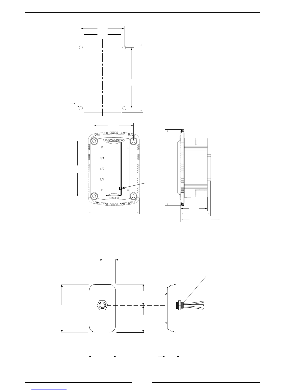
1. Measure and mark mounting location for display module panel cutout and
mounting screw holes. Make sure there is clearance behind the panel for
the display and cables before cutting holes. Refer to Figure 1 for layout and
dimensions.
2. Cut out a 4 by 2 1/8-inch hole and drill four (4) holes (clearance or tapped) for
#10 mounting screws.
3. Place display module in position and secure with four (4) screws.
4. Connect the display module cables and wires. (Refer to Wiring Section.)
Install Cab Miniature Display
1. Measure and mark mounting location for cab miniature display mounting hole.
Make sure there is clearance behind the panel before drilling hole. Refer to
Figure 2 for layout and dimensions.
2. Drill a clearance hole for 3/8" threads.
3. Place cab miniature display in position and secure with nut.
4. Connect the cab miniature display wires. (Refer to Wiring Section.)
9
WLA300 Rev170606
Mounting holes are
clearance or tapped
for #10 screws.
4 pl
2 1/2"
2 1/8"
C
L
2 1/2"
Panel Cutout
C
L
4"
3 1/2"
Note: Do not use Loctite on
any screws near the Lexan
lens. Lexan lenses can become
brittle and prone to cracking when
exposed to Loctite compounds.
3 1/2"
3 1/4"
4 11/16"
Photo
Sensor
(Internal)
1 5/8"
1 7/8"
2 7/16"
(with connector)
Figure 1. Display Module Mounting Dimensions
3/4"
Drill a clearance hole
for 3/8" threads.
1 3/16"
2 3/4"
1 1/2"
Figure 2. Cab Miniature Display Mounting Dimensions
1 9/16"
5/8"
10

WLA300 Rev170606
Install Pressure Sensor
The pressure sensor is mounted on one of the tank sides approximately 2 inches
from the bottom. If the tank has a vertical height greater than 10 feet contact FRC, a
different sensor may be required.
Pressure sensors are interchangeable. It is recommended that the calibration
procedure be performed if the pressure sensor is changed.
Note: When mounting the pressure sensor on a tank with thin walls, less
than 3/8", it is recommended that the tank wall be reinforced at the sensor
mounting location.
Pressure Sensor Installation
Note: Do not mount the sensor in the bottom of the tank. Sediment may collect in the port
and cause sensor failure.
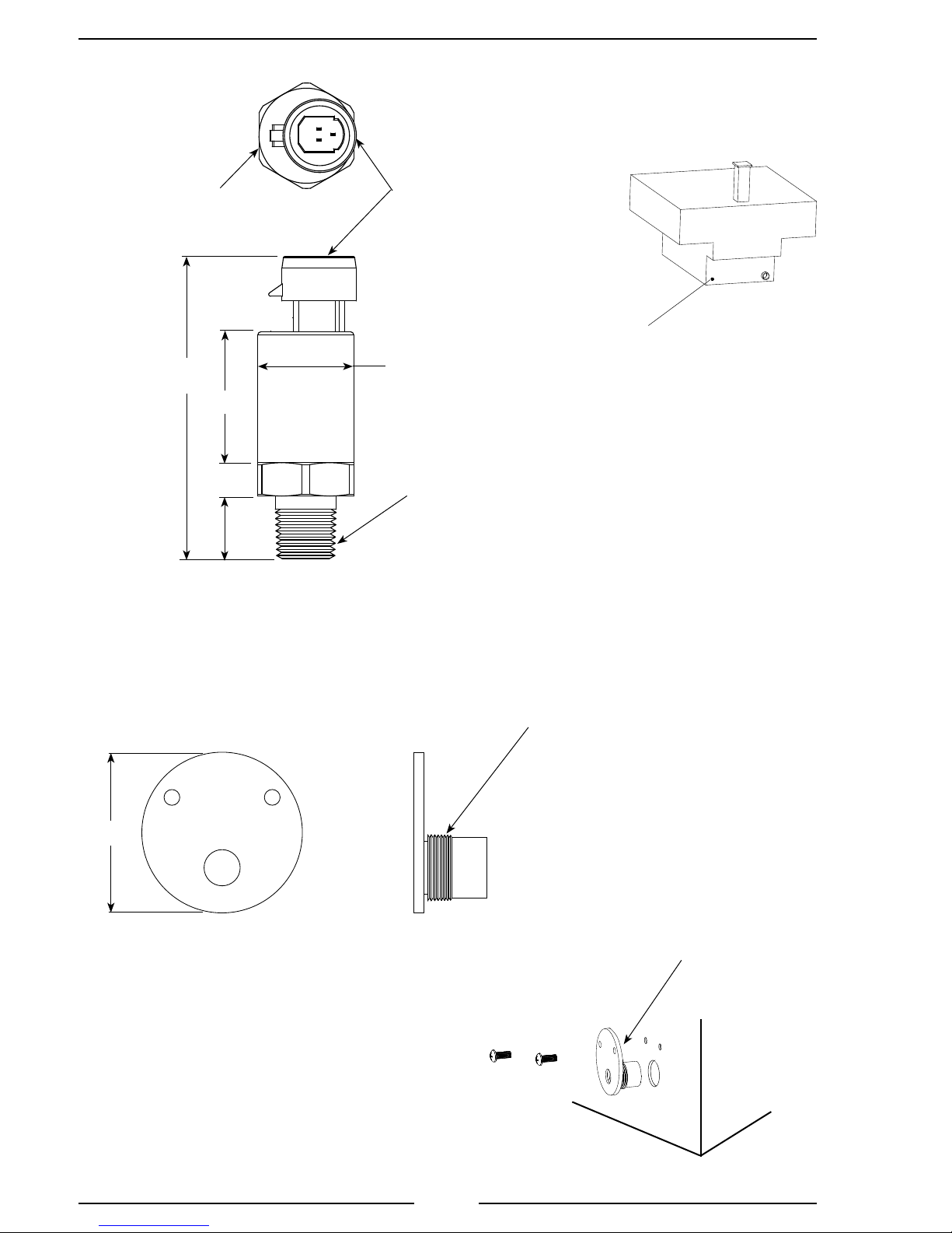
1. Measure and mark mounting location for sensor. (Mounting hole should be
approximately 2" from bottom of tank.) Make sure there is clearance for sensor
and cable before drilling hole. Refer to Figure 3 for dimensions.
2. Drill and tap a 1/4 NPT hole.
3. Apply sealant around base and threads of pressure sensor.
4. Screw sensor into hole.
5. Connect sensor cable. (Refer to Wiring Section.)
Thin Wall Adapter Installation
The thin wall adapter kit includes the adapter, two 10-24 x 5/8" screws, 5 minute
epoxy, and a mixing stick.
1. Measure and mark mounting location for adapter. Make sure there is clearance for
adapter, sensor, and cable before drilling hole. Refer to Figure 3 for dimensions.
2. Drill and tap a 1/2 NPS hole.
3. Screw the adapter into the hole.
4. Use the adapter as a template and drill and tap two 10-24 holes for two screws.
5. Back adapter out of hole and apply 5 minute epoxy to back of ange, on threads,
and in two 10-32 through holes.
6. Screw adapter into hole and secure with two screws.
7. Allow the epoxy time to set.
8. Apply sealant around base and threads of pressure sensor and screw into adapter.
9. Connect sensor cable. (Refer to Wiring Section.)
11
WLA300 Rev170606
Mount sensor approximately
2" from bottom of tank.
7/8"
Across Flats
2.8"
(max)
1.1"
0.6"
Apply sealant around
base and threads.
3-Pin
Packard Plug
0.87"
1/4 NPT
Typical
Tank
Typical Pressure
Sensor Location
Note: Do not mount the sensor in the
bottom of the tank. Sediment may collect
in the port and cause sensor failure.
Note: The sensor can be mounted
vertically on a 90° tting in cold areas to
help prevent water freezing in the sensor.
Thin Wall Adapter
2"
Apply sealant
around base and
threads of sensor.
1/2 NPS
Apply epoxy around
ange, threads, and
screws.
Figure 3. Pressure Sensor
12

WLA300 Rev170606
Install Pressure/Vacuum Foam Tank Vent
A pressure/vacuum foam tank vent is supplied for use on sealed foam tanks. The
recommended location to mount the vent is in the cover of the foam tank ll tower. If
there is no ll tower, mount the vent at the highest point of the tank top so that it is not
immersed in foam. For installations where clearance above the ll tower is limited, a
90° mounted vent is available.
Note: The vent can compensate for a maximum foam concentrate ow rate
of 60 GPM. If the ow rate of foam concentrate from the tank will exceed
60 GPM, two (2) vents will be required.
Install Top Mounted Tank Vent
The top mounted tank vent is mounted in a vertical position through a 1 1/8-inch
hole on the lid of the ll tower and is secured by a hand tightened nut.
Note: The tank vent must be in a vertical position and can not be immersed
in foam.
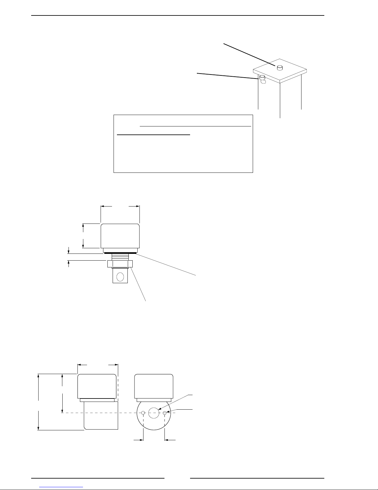
1. Measure and mark mounting location for vent. Make sure there is clearance
for the valve before drilling hole. Refer to Figure 4 for dimensions.
2. Drill 1 1/8-inch diameter hole.
3. Insert vent into the hole with the gasket in place.
4. Screw on nut and hand tighten.
Install 90° Mounted Tank Vent
The 90° mounted tank vent is mounted on a vertical side of the ll tower. It must
be located as close to the top of the ll tower as possible. The vent is held in place with
two (2) 1/4-20 x 3-inch bolts, washers, and locknuts.
Note: The tank vent must be in a vertical position and can not be immersed
in foam.
1. Measure and mark mounting location for vent. Make sure there is clearance
for the valve before drilling holes. Refer to Figure 4 for dimensions.
2. Drill 3/4-inch diameter hole and two through holes for 1/4-20 bolts.
3. Apply sealant to mounting surfaces and bolt holes.
4. Secure vent in place with two bolts, washers, and locknuts.
13
WLA300 Rev170606
90° Mounted Tank Vent
3/4" Diameter Hole with
ll tower, mount the vent at the highest
Top Mounted Tank Vent
2 1/2"
Top Mounted Tank Vent
1 1/8" Diameter Hole
Two 1/4" Bolt Holes
Note: The tank vent must be mounted
in a vertical position. The vent can not
be immersed in foam. (If there is no
point of the tank top so that it is not
immersed in foam.)
Typical
Foam Tank
Fill Tower
1 3/4"
5/8"
Maximum Mounting
Surface Thickness
90° Mounted Tank Vent
2 5/8"
2 5/8"
3 7/8"
Gasket (Between Mounting
Surface and Tank Vent)
Nut (1 1/8" - 12 TPI)
3/4" Dia.
1/4" Dia.
(Thru holes for two
1/4-20 x 3" bolts.)
Figure 4. Pressure/Vacuum Foam Tank Vent
1 1/2"
14
 Loading...