

FRC ICA100, Surface Mount ICA200 Series, Surface Mount ICA300 Series, Flush Mount ICA400 Series, Flush Mount ICA500 Series Series Manual

Document Number:
XE-ICA1PM-R0A
AMBULANCE/RESCUE VEHICLE
ICA100 Rev171109
INTERCOM
MODEL ICA100
SURFACE MOUNT SERIES
MODELS ICA200, ICA300
FLUSH MOUNT SERIES
MODELS ICA400, ICA500
ICA100
ICA200/300
ICA400/500
FIRE RESEARCH CORPORATION
www.reresearch.com
26 Southern Blvd., Nesconset, NY 11767
TEL 631.724.8888 FAX 631.360.9727 TOLL FREE 1.800.645.0074
1

ICA100 Rev171109
CONTENTS
Table of Contents
CONTENTS ................................................................................................................ 2
INTRODUCTION ...................................................................................................... 3
Overview ................................................................................................................ 3
Features .................................................................................................................. 3
Specications ......................................................................................................... 3
GENERAL INSTALLATION NOTES ....................................................................... 4
ICA100 SERIES INSTALLATION ............................................................................ 5
Pre-Installation ....................................................................................................... 5
Install Remote Station ............................................................................................ 5
Install Master Station ............................................................................................ 5
ICA200/300 SERIES INSTALLATION ..................................................................... 8
Pre-Installation ....................................................................................................... 8
Install Remote Station ............................................................................................ 8
Install Master Station(s) ......................................................................................... 8
ICA400/500 SERIES INSTALLATION ................................................................... 12
Pre-Installation ..................................................................................................... 12
Install Remote Station .......................................................................................... 12
Install Master Station(s) ...................................................................................... 12
OPERATION ............................................................................................................ 16
Basic Two-Way System ....................................................................................... 16
Basic Three-Way System ..................................................................................... 16
System Options .................................................................................................... 16
Operational Check ............................................................................................... 17
List of Tables
Table 1. Intercom Specications ................................................................................ 3
List of Figures
Figure 1. ICA100 Mounting Dimensions .................................................................. 6
Figure 2. ICA100 Wiring ........................................................................................... 7
Figure 3. ICA200/300 Adjustable Mount .................................................................. 9
Figure 4. ICA200/300 Mounting Dimensions ........................................................... 9
Figure 5. ICA200 Wiring ......................................................................................... 10
Figure 6. ICA300 Wiring ......................................................................................... 11
Figure 7. ICA400/500 Mounting Dimensions ......................................................... 13
Figure 8. ICA400 Wiring ......................................................................................... 14
Figure 9. ICA500 Wiring ......................................................................................... 15
2

ICA100 Rev171109
INTRODUCTION
Overview
Fire Research intercoms are designed to meet rescue and re service requirements
for two or three-way voice communications system. The ICA100 series intercom
systems are designed for use inside ambulances and rescue vehicles. The ICA200/300
surface mount and ICA400/500 ush mount series intercom systems are weatherresistant and specically designed for outside use on re service apparatus.
Features
Master station with volume and push-to-talk controls
Remote station is operated hands free
Dual master stations for three-way systems
Adjustable mount (ICA200/300 Series)
Hand-held microphone option for master stations
Foot switch option for master stations
Specications
Table 1. Intercom Specications
SERIES ICA100 ICA200/300 ICA400/500
SUPPLY
VOLTAGE
OUTPUT
POWER
FUSE
DIMENSIONS
MASTER
(IN INCHES)
12 VDC 12 VDC 12 VDC
8 WATTS 16 WATTS 16 WATTS
3 AMP
RECOMMENDED
5.25 x 4 x 1.5
3 AMP
SLOW BLOW
.25" X 1.25" MDL
8.25 x 5.625 x 3
(Without Bracket)
3 AMP
SLOW BLOW
.25" X 1.25" MDL
6.25 x 7.25
(Panel Dimensions)
3" Clearance Required
Behind Panel
DIMENSIONS
REMOTE
(IN INCHES)
Handheld
Microphone
PTT Button for
Remote Station
5.625 x 6
4.375 x 3.25 x 1.5
N/A Optional Optional
Optional Optional Optional
5.25 x 5.25 x 2.25
(Without Bracket)
3
(Panel Dimension)
2.5" Clearance Required
Behind Panel

ICA100 Rev171109
GENERAL INSTALLATION NOTES
Mount the intercom stations in locations that are safe and convenient for use.
It is recommended that the master station be mounted inside the cab.
Consider potential background noise that the hands free remote station might
pick up.
If excess background noise is picked up by the hands free remote station due to
vibration, mounting it on a rubber pad can help reduce noise.
Ensure a good ground connection. Isolate the intercom ground wire from other
grounds that can be noisy (strobes, radios, priming motors, etc.).
Make interconnecting cable runs as short as possible.
Secure excess intercom cable in a gure 8 pattern.
The foot switch option requires the installation of a single-pole single-throw
switch (not supplied with intercom).
4

ICA100 Rev171109
ICA100 SERIES INSTALLATION
Pre-Installation
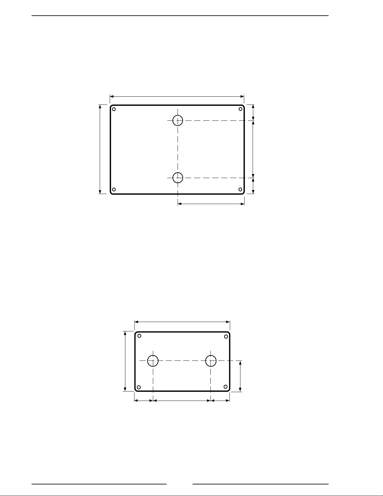
1. Measure and mark station locations for two mounting holes. Refer to Figure
1 for layout and dimensions.
2. Drill two 3/4-inch mounting holes at each station location.
3. Install the four conductor cable between station locations.
4. Remove nuts from mounting post on intercom boxes.
Install Remote Station
1. Place station box in position with mounting post through the holes and secure
with two nuts. (The nuts should be hand tight plus 1/4 turn.)
2. Connect station box four wires to cable. Refer to Figure 2 for wiring details.
Install Master Station
1. Place station box in position with mounting post through the holes and secure
with two nuts. (The nuts should be hand tight plus 1/4 turn.)
2. Connect station box four wires to cable. Refer to Figure 2 for wiring details.
3. Connect black wire to ground.
4. Connect red wire to +12 VDC.
5
ICA100 Rev171109
Master Station
Two 3/4” holes are
needed.
5 1/4"
3/4"
Remote Station
4"
4 3/8"
2 1/2"
3/4"
2 5/8"
Two 3/4" holes are
needed.
3 1/4"
1 5/8"
1 1/16"
2 1/4"
1 1/16"
Figure 1. ICA100 Mounting Dimensions
6
 Loading...