

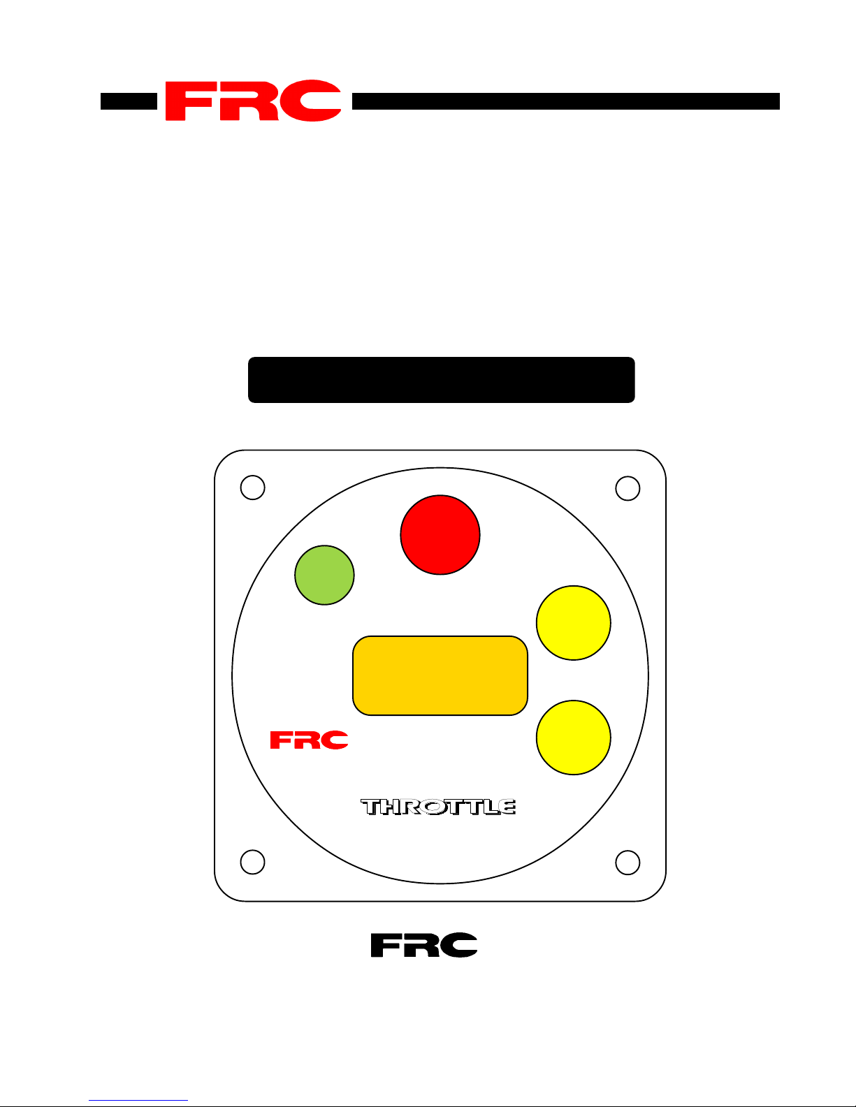
REMOTE THROTTLE
FOR CUMMINS CELECT and CELECT+
ENGINES SERIES M11, N14, L10
MODEL : RTU 1
OPERATING INSTRUCTIONS
IDLE
REV1297NB RTU1.P65
PRESETPRESET
PRESET
PRESETPRESET
INCREASE
FRC
s
12001200
1200
12001200
s
SETTING
DECREASE
RTU
FIRE RESEARCH CORP. 26 Southern Blvd., Nesconset, NY11767
TEL ( 516 ) 724-8888 FAX ( 516 ) 360-9727
TOLL FREE 1-800-645-0074
Page 1

RTU
Remote Throttle
Introduction:
The R TU is a state of the art electronic remote throttle designed for fire apparatus
equipped with the Cummins CELECT and CELECT+ electronic engine control
system. This includes the M11, N14 and L10 series engines. The RTU is connected
to the CELECT or CELECT+ through the J1922 data link via a twisted pair cable.
This arrangement allowes the MP ( master processor ) of the R TU to communicate
with the ECM (electronic control module) of the engine constantly . The RTU can be
used to vary the engine speed through use of the "INCREASE" and "DECREASE"
pushbuttons. A "PRESET" switch allows an operator to quicly bring the engine RPM
to a predetermined value with one press of a button.
An optional high idle kit (PRO-38H) may be purchased that plugs directly into the
R TU that allows engine RPM to be brought to a preselected RPM value through a
toggle switch. Wiring for this option can be found in Fig 7 of this manual.
REV1297NB RTU1.P65
Page 2

MECHANICAL INSTALLATION
Before proceeding with any installation, please check to make sure you have the following components. STOP and call the factory if any components are missing. Components supplied are as follows :
1) Throttle controller
2) Extension cable for power
3) Extension cable for J1922 data link
MECHANICAL - installing the display module
The control module can be mounted anywhere on the pump panel. The display module
has a square flange with overall dimensions of 4.25"X4.25". A cutout hole of 3.75" in
diameter is required to fit the cylindrical can of the module into the panel. Insert the
Throttle controller into the cutout hole and locate the four bolt holes. The holes are for
10-32 screws and are set up on a 3.5" bolt square at the four corners of the flange.
REV1297NB RTU1.P65
(Some units are longer)
Page 3
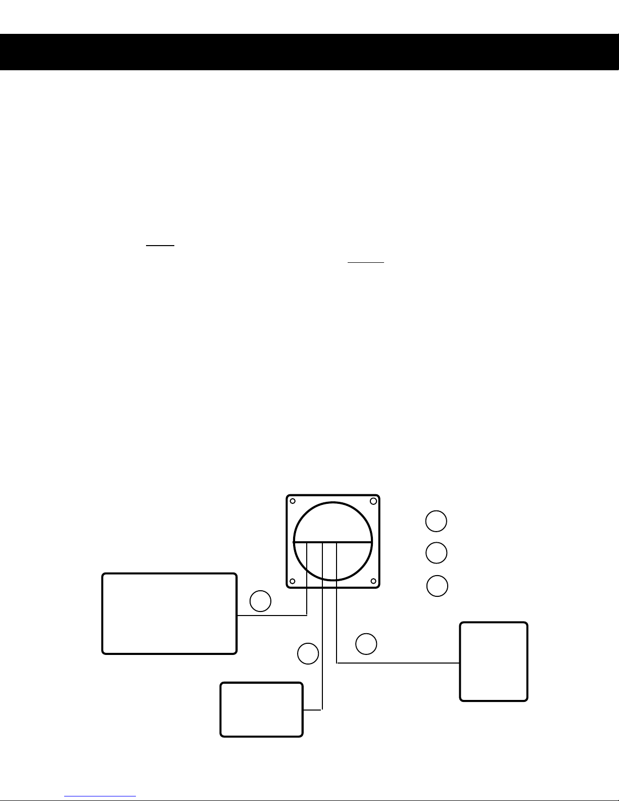
ELECTRICAL INSTALLATION
Wiring for the RTU 1 system is very simple. Refer to fig 1 below. All extension cables are
supplied with unique connectors that simplify the interconnections. See fig 2 for cables.
1) Use the extension cable supplied, provide 12VDC and ground to the electronic
module on the wire labeled POWER on the back of the module. Leave the white wire
disconnected until step 3.
2) Connect the cable for the J1922 data link. The J1922 datalink is a data wire consisting
of two wires leading from connector A of the ECM. On more recent Cummins ECMs
(CELECT+),
pin 5 on connector A of the ECM is the positive (+) (wire #020) and should
be connected to the R TU's red DATA J1922 wire. Pin 23 is the negative (-) (wire #021)
and should be connected to the R TU's black DATA J1922 wire. The cable used is a
shielded twisted pair cable.
NOTE:
If you have an older Cummins CELECT engine, there may be a 2 pin Packard connector
for the J1922 data link located near the CELECT ECM by the bulkhead. Check that the
positive (+) wire comes from pin 10 on the A connector. The negative (-) comes from pin
20 on the A connector.)
3) The R TU will not be active until you provide 12V to the white wire. This connection
should be wired through the pump engaged interlock and the parking brake for safety . In
this manner, the RTU will not receive an "active" signal until these conditions are met.
4) If HIGH IDLE option was
CONTROL MODULE
ordered, refer to Figure 7 for
wiring instructions.
REV1297NB RTU1.P65
RED = 12 VDC
BLACK = GND
WHITE = Interlock.
12VDC signal required
FIG 1.
1
CELECT
ECM
RTU 1
2
Page 4
Power cable
1
J1922 data link cable
2
High Idle cable
3
3
HIGH
IDLE
Refer to Figure 7

EXTENSION CABLES
POWER
RED = 12VDC
Figure 2
THROTTLE
RTU 1
BLACK = GND
DA TA LINK
J1922
REV1297NB RTU1.P65
HIGH IDLE
Red = 12VDC
Black = GND
White = From INT-110
3 pins plug
Deutsch DT series
3 pins receptacle
Deutsch DT series
T o High Idle inside cab
(see Fig 7)
To J1922 data link
at CELECT ECM
5'
Power
12'
High Idle
12'
2 pins Packard plug 2 pins Packard receptacle
J1922 data link
Page 5

OPERATING THE RTU
Simple to use !
The R TU is engineered with ease of operations in mind. All functions on the control
module are self explanatory . The LED display which shows the desired RPM setting is
easily visible both day and night.
How to operate :
When the R TU is on, the display will show 'IDLE' to indicate that the engine is at idle.
There are 4 pushbuttons on the control module :
1) The "Increase" and "Decrease" switches allow easy selection of desired RPM from
IDLE to maximum governed speed. Depress "Increase" to ramp the engine RPM up,
and depress "Decrease" to ramp the engine RPM down. The RPM will ramp up or
down at 50 RPM increment when pressed momentarily . When the pushbutton is held
down for more than 2 seconds, the R TU will ramp up or down in 100 RPM increments.
Release the pushbutton when desired RPM is reached.
REV1297NB RTU1.P65
2) The "IDLE" switch will bring engine to idle immediately after operations.
3) The "PRESET" switch ramps engine to the preset RPM quickly and conveniently
with the momentary touch of a single button.
(After the "PRESET" switch is used, the "Increase" and "Decrease" switches can still
be used to change the selected RPM easily.)
How do I change the preset RPM ?
a) Make sure the engine is at idle before proceeding. If the R TU does not display IDLE
in the display window , press the "IDLE" switch.
b) Press the "PRESET" switch with your left thumb and hold it in until the display
begins to flash. With your right hand press the "Increase" or "Decrease" switch to
change the flashing display until it reads the desired RPM.
c) When the desired RPM is obtained, release the "PRESET" switch and the RPM
shown in the window has become the new preset RPM and will be stored in the R TU's
memory .
Page 6

FUNCTIONS FOR SWITCHES ...
Figure 3
4
PRESETPRESET
PRESET
PRESETPRESET
FRC
1
IDLE
12001200
1200
12001200
SETTING
RTU
INCREASE
s
2
s
3
DECREASE
REV1297NB RTU1.P65
1) The " IDLE " switch brings engine to idle immediately after operations
2) The " INCREASE " switch ramps engine RPM up
3) The " DECREASE " switch ramps engine RPM down
4) The " PRESET " switch ramps engine to the preset RPM quickly and conveniently .
Page 7

Specifications :
Control Module :
Dimensions :
Response : Idle to full governed speed
Pressure Recovery : On open/close valve
Max. RPM :
Operational :
RPM mode :
Electrical :
Power :
Current :
Microprocessor :
4.25"W X 4.25"H X 3.75"D
3 seconds maximum
1 1/2 seconds
2000 RPM
REV1297NB RTU1.P65
Idle to 2000 RPM
12 VDC
1/2 A continuous
8 Bit single chip MicroComputer
Page 8

X-Hi-Idle.p65 rev11Sep97nb
OPTIONAL
HIGH IDLE
OPERA TION
Part # PRO-38H
If you did not order the optional remote high idle, ensure that the
dummy plug (supplied) is installed on the end of the high idle cable! If
you did not receive a dummy plug, or have lost it, you NEED one!
For wiring instructions, refer to the next page.
All Fire Research PRO and RTU series governors have an additional cable port
labeled “high idle” which can be used to provide a high idle switch at a remote location
on the vehicle. The PRO-38H High Idle Kit provides all the necessary components
needed to hook up this optional switch, including locking potentiometer, dpdt switch,
12V lamp indicator and 12 foot cable.
How do I activate the high idle ?
T o activate the high idle, simply toggle the high idle switch to “ON”. The high idle
activated indicator light will go on and the engine will rise to the preset speed (set by
the locking potentiometer).
How do I change the high idle speed ?
Loosen the lock nut on the potentiometer . Use a small screw driver to rotate the potentiometer to raise the RPM. Using the tachometer in the cab as a reference, monitor the
speed of the engine until you reach the desired speed. Once the desired RPM is
reached, tighten the lock nut to lock in the new high idle speed.
WARNING : Turn off high idle before shutting the engine off !
Page 9

X-Hi-Idle.p65 rev11Sep97nb
OPTIONAL
HIGH IDLE
From Control Module
Red
Black
WIRING
Supply 12 VDC when the parking
brake is on and the transmission is in
White
neutral.
Part # PRO-38H
GND
2500 ohm potentiometer
High idle indicator light
High idle ON/OFF switch
Diode
Figure 7
O.K. to pump
Interlock
white wire on the
power cable
Diode
Note: Some FRC governors require an RPM sensor to be mounted on the drive shaft.
If you have one of these units, be sure that the sensor is mounted on a section of shaft
that spins even when the pump is not engaged or the high idle may not be able to function
except when the pump is in gear. If there is no room to mount the sensor in such a
location, a special “Alternator connection” for RPM signal may be required. This option
may not be available for all devices, so be sure to call FRC for details.
Page 10

Field Service and Warranty
Our aim is to minimize or eliminate field service, so be sure to call technical support (800) 645 0074 as soon as you think there may be a problem in operation or
installation of the R TU governor . A simple call will go a long way toward quickly
diagnosing a problem and determining what parts, if any , may need to be replaced
under this warranty .
Fire Research Corp. (FRC) warrants to replace the RTU unit for any defect in materials or workmanship. This warranty shall apply for a period of one
year after the unit goes in service. This period will begin upon official delivery
date of the vehicle by a truck body manufacturer or upon installation by the
enduser in cases where the unit is retro-fit to an existing unit.
During the warranty period, FRC will replace any of the component parts of a
defective unit by next day air freight by UPS or comparable courier, as our
stock permits, free of charge.
REV081597NB
After the warranty period, FRC warrants to ship to the customer by quickest way , a
temporary unit (as stock permits) for the customer to use while the defective unit is
being repaired in order to minimize down time.
As the PRO was designed to be extremely reliable and has passed stringent third
party testing, FRC expects minimal field defects.
Page 11
 Loading...