


inView 360 Fusion
Installation Guide
© Safe Fleet | September 2018 | All rights reserved
Document #: XE-SNB1-Install-PM-R0A

inView 360 Fusion Installation Guide
CONTENTS
Table of Contents
CONTENTS
CONTENTS � � � � � � � � � � � � � � � � � � � � 2
Introduction� � � � � � � � � � � � � � � � � � � � � 3
Installation Principles � � � � � � � � � � � � � � � � � � � � � �3
System Components � � � � � � � � � � � � � 3
Recommended Tools � � � � � � � � � � � � � 5
Installation Diagram � � � � � � � � � � � � � � 6
ECU Installation � � � � � � � � � � � � � � � � � 7
Selecting a Mounting Location� � � � � � � � � � � � � � �7
Installing the ECU� � � � � � � � � � � � � � � � � � � � � � � � �7
ECU Installation Requirements� � � � � � � � � � � � � � �8
Installing Power & Interface
Installing the Cameras � � � � � � � � � � � � � � � � � � � �16
Determining Camera Locations � � � � � � � � � � � � � 17
Hard-Mounting Cameras � � � � � � � � � � � � � � � � � � 19
Test and Calibrate� � � � � � � � � � � � � � � � � � � � � � � �20
Support Information � � � � � � � � � � � � � 24
Contacting FRC (Fire Research Corporation) � � 24
Warranty � � � � � � � � � � � � � � � � � � � � � � � � � � � � � � �24
Components � � � � � � � � � � � � � � � � � � � � 9
Installing the harness � � � � � � � � � � � � � � � � � � � � � � 9
Connecting the Driver Button � � � � � � � � � � � � � � �10
Connecting the Remote Control Receiver � � � � � 11
Installing Video Components � � � � � � 11
Installing the harness � � � � � � � � � � � � � � � � � � � � � 11
Mounting the Monitor � � � � � � � � � � � � � � � � � � � � �12
Connecting the Monitor � � � � � � � � � � � � � � � � � � �13
Monitor Settings � � � � � � � � � � � � � � � � � � � � � � � � � 14
Assembling the Cameras � � � � � � � � � � � � � � � � � �15
Soft-Mounting Cameras � � � � � � � � � � � � � � � � � � � 16
p. 2
© Safe Fleet | September 2018 | All rights reserved
Document #: XE-SNB1-Install-PM-R0A

inView 360 Fusion Installation Guide
Introduction
Introduction
This guide describes how to install and use the inView 360-Fusion Around Vehicle Monitoring (AVM ) system� inView
360-Fusion provides drivers with a real-time, 360-degree picture of the area around their vehicle to eliminate blind spots,
help improve pedestrian safety, prevent vehicle damage, and avoid liability costs�
Installation Principles
Installation of the inView 360 Around Vehicle Monitoring system is for certied personnel only. For more information on
the certication process, please contact the FRC Service Team (please see the back of this guide for details).
The installation process involves drilling into the exterior of a vehicle to mount cameras� Ensure you read this document
carefully, and verify the correct mounting locations prior to drilling�
NOTE: The installed system will not operate correctly until it has been calibrated. For more information,
see the inView 360 Calibration Guide included in the Calibration Kit.
System Components
The inView 360-Fusion installation package contains the following components:
Electronic Control Unit (ECU) Components
1x ECU Mounting
1x ECU (Electronic Control Unit)
Bracket w/ 4x Screws
p. 3
© Safe Fleet | September 2018 | All rights reserved
Document #: XE-SNB1-Install-PM-R0A

inView 360 Fusion Installation Guide
Power & Interface Components
1x Power & Interface Harness
Introduction
1x Reverse Signal Wire
2x In-line Fuses
(1A & 3A)
1x Button Extension Cable & 1x Driver Button
Video Components
1x Video Harness
2x Video Output Extension Cables
1x Left (Orange) & 1x Right
(Brown) Signal Wires
4x Camera Mounting Kits (Each
kit incl. 1x Cover, 1x Bracket,
2x Camera Screws, 2x Bracket
Screws
4x Camera Extension Cables
4x Drilling Templates & 8x Screw Covers
p. 4
© Safe Fleet | September 2018 | All rights reserved
4x Cameras
Document #: XE-SNB1-Install-PM-R0A

inView 360 Fusion Installation Guide
Monitor Components
1x Monitor
Base
1x Remote
(NOT USED)
Recommended Tools
1x Monitor
Adhesive Pad
Video Cable
(attached to
monitor)
1x Monitor
Recommended Tools
The following is a list of recommended tools for installing the inView 360-Fusion:
• Multimeter
• Electrical tape
• Soldering iron and solder
• Cordless Drill
• Phillips screwdrivers
• Phillips drill attachments
• Wire cutters
• Zip ties
• 1/8”, 1/16” Drill bits
• 3/4” Stepbit (Unibit)
• Crimpers
• Wire sh tape
p. 5
© Safe Fleet | September 2018 | All rights reserved
Document #: XE-SNB1-Install-PM-R0A
inView 360 Fusion Installation Guide
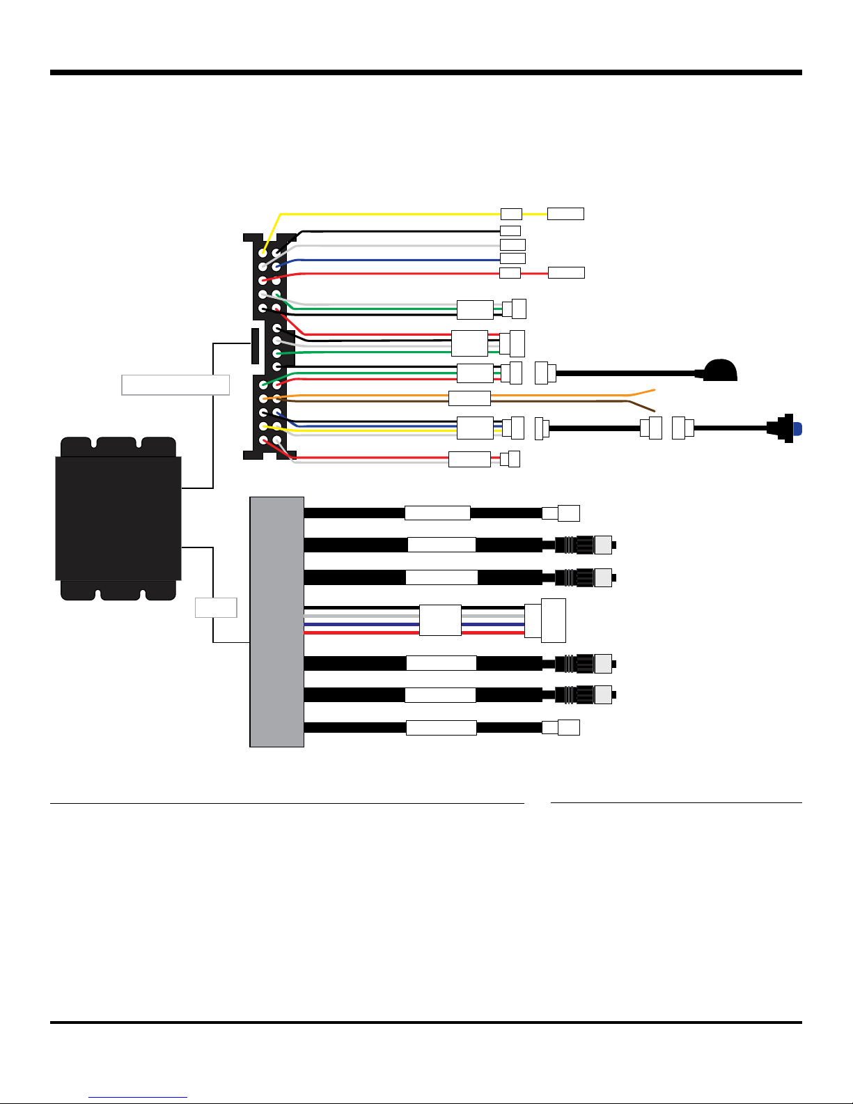
Installation Diagram
Installation Diagram
The inView 360-Fusion comes with two main connection harnesses, one for Power & Interface, and one for Video�
The following diagram provides a breakdown of each.
VBAT
GND
VOUT
GEAR
ACC
TOUCH
OBD
IrDA
+3A Fuse
+1A Fuse
Power & Interface
FLASHER
BUTTON
SPEAKER
MCU UPDATECPU UPDATE
POWER & INTERFACEVIDEO
CVBS2
FRONT CAM
REAR CAM
Video
DVR
LEFT CAM
RIGHT CAM
CVBS1
Power & Interface Harness Legend Video Harness Legend
• VBAT - Yellow - Battery
• GND - Black - Ground
• VOUT - White - Not Used
• GEAR - Blue - Reverse
Signal
• ACC - Red - Ignition
• TOUCH - Not Used
• OBD - Not Used
• IrDA - Remote Control Sensor
• Flasher - Orange (Left), Brown
(Right) Signal
• BUTTON - Driver Button
• SPEAKER - Not Used
p. 6
• CVBS1 - Monitor
• CVBS2 - DVR
• DVR - Not Used
© Safe Fleet | September 2018 | All rights reserved
Document #: XE-SNB1-Install-PM-R0A

inView 360 Fusion Installation Guide
ECU Installation
ECU Installation
Selecting a Mounting Location
The inView 360-Fusion ECU needs to be installed in a dry, covered location with easy access to the SD card port�
Here are a few idea locations for mounting the ECU in a vehicle:
SD Card Slot
Installing the ECU
Once you’ve determined your ECU mounting location, you’re ready to install it in the vehicle�
1� Place the ECU and mounting bracket in position. The bracket can be mounted on either side of the ECU.
2� Mark your drill positions.
3� Drill the screw holes�
4� Mount the ECU and bracket .
p. 7
© Safe Fleet | September 2018 | All rights reserved
Document #: XE-SNB1-Install-PM-R0A

inView 360 Fusion Installation Guide
ECU Installation
ECU Installation Requirements
Ventilation
• Install the ECU away from any sort of heat outlet, heater, or AC blower�
• Do not operate the ECU in a closed-in area or restrict ventilation in any way� The ECU requires air circulation to
maintain optimum operating temperature and provide best performance�
• Do not expose the ECU to moisture�
Secure Surfaces
• Do not mount the ECU to a plastic panel or other surface that cannot support the ECU’s weight or is subject to
constant vibration�
Mounting Orientation
• The ECU can be installed horizontally, vertically, or upside down�
Clearance Around the ECU and (optional) DVR
• Allow sufcient clearance: at least 6” in front of the ECU and 2” on each side for removal of the security front
cover and easy access to the hard drive and USB ports�
• Allow sufcient clearance behind the DVR for power, signal, and camera cables.
Power, Signal & Camera Cables
• Provide enough slack on the power cable to prevent any force from being exerted on the connectors.
• A single 4-inch diameter loop is sufcient.
• Avoid right angle bends in the Ethernet cables�
p. 8
© Safe Fleet | September 2018 | All rights reserved
Document #: XE-SNB1-Install-PM-R0A

inView 360 Fusion Installation Guide
Installing Power & Interface Components
Installing Power & Interface Components
Installing the harness
The Power & Interface harness connects the ECU to the vehicle’s power, ignition, ground, and directional signals (left,
right, reverse)� In addition, the harness provides power to the AVM’s remote control sensor and driver button�
To install the harness properly:
• Connect the GND (Black) wire to an appropriate vehicle ground source.
• Connect the VBAT (Yellow) wire to the vehicle’s constant power source via the 3A fuse�
• Connect the ACC (Red) wire to the vehicle’s ignition source via the 1A fuse�
p. 9
© Safe Fleet | September 2018 | All rights reserved
Document #: XE-SNB1-Install-PM-R0A
ACC w/1A FuseVBAT w/3A Fuse

inView 360 Fusion Installation Guide
• Connect the GEAR (Blue) wire to the vehicle’s reverse signal source (via extension wire)� This source must be
positive (12v when the vehicle is put in reverse)�
• Connect the FLASHER connector (via extension cable) to the vehicle’s front turn signal sources (Orange for left,
Brown for right)� These sources must also be positive (12V when the left or right turn signals are on)�
Installing Power & Interface Components
Connecting the Driver Button
The Driver Button lets the operator switch between the front, rear, left, and right camera views on the in-cab monitor�
To install the driver button:
1� Choose a location in the vehicle� Ideally, the location should be within arm’s reach of the driver�
2� Drill a 7/16” hole�
3� Thread the button through the hole�
4� Tighten the nut to the underside of the button�
5� Connect the button to the extension cable�
6� Run the extension cable to the ECU�
7� Connect the extension cable to the BUTTON connector on the Power & Interface harness�
p. 10
© Safe Fleet | September 2018 | All rights reserved
Document #: XE-SNB1-Install-PM-R0A

inView 360 Fusion Installation Guide
Connecting the Remote Control Receiver
The receiver allows the 360 remote control to communicate with the ECU�
To install the receiver:
1� Remove the remote control receiver from the inView 360-Fusion Calibration Kit�
2� Find an optimal position to place the receiver�
3� Run the receiver cable to the ECU and connect it to the IrDA (Black/Green/Red) connector.
Installing Video Components
Installing Video Components
Installing the harness
The video harness connects the ECU to the cameras and monitor� There are 4 camera inputs, and 2 video outputs�
The camera inputs are labeled Front, Right, Rear, Left, and must be connected to the corresponding cameras� The 2
outputs are for monitor and a DVR connection�
Video Outputs to
Monitor or DVR
p. 11
Camera inputs
© Safe Fleet | September 2018 | All rights reserved
Document #: XE-SNB1-Install-PM-R0A

inView 360 Fusion Installation Guide
Installing Video Components
Mounting the Monitor
When mounting the monitor, ensure that it is in a location that doesn’t obstruct the driver’s view� To install the monitor:
1� Choose a mounting location for the monitor� When in place, the
monitor is supported between the vertical arms of the mounting
bracket.
2� Position the bracket and use the 2 self-tapping screws
from the hardware kit to attach the bracket to the mounting
surface�
3� Install the “L” brackets on the back of the monitor housing
(one bracket on each side):
a� As shown in the following diagram, position the “L”
bracket so the holes line up with the holes in the
housing. The bracket only ts one way, and you’ll need
to slide the inner edge slightly toward the center and
underneath the slot in the housing�
b� Use 2 countersunk screws to attach each bracket to
the housing�
4� Attach the sun shade:
a� Position the sun shade frame around the front of the
monitor, with the shade at the top�
b� Fit the bottom of the monitor into the shade frame rst,
then snap the rest of the frame onto the monitor housing
until it ts snugly.
5� Use 4 knob-head screws through the “L” brackets to attach the
monitor to the mounting bracket.
6� Adjust the monitor tilt as required and tighten the mounting
screws�
p. 12
© Safe Fleet | September 2018 | All rights reserved
Document #: XE-SNB1-Install-PM-R0A

inView 360 Fusion Installation Guide
Installing Video Components
Connecting the Monitor
Once the monitor is mounted in position, you'll need to connect its harness to power, then connect it to the ECU's
video harness� To do this:
1� Connect the black wire to an appropriate ground source�
2� Connect the yellow and red wires to the vehicle's ignition source�
3� Connect the AV1 cable (with yellow connector) to the AV adapter�
4� Connect the video (yellow) connector of the AV adapter to the CVBS connector on the ECU video harness (via
extension cable)�
Video extension
cable
IGN
GND
IGN
AV Adapter
Video
Harness
p. 13
© Safe Fleet | September 2018 | All rights reserved
Document #: XE-SNB1-Install-PM-R0A

inView 360 Fusion Installation Guide
Monitor Settings
Menu Item Options Description Value Range
(Default in bold)
Brightness AV1, AV2, AV3 Adjust image property 0–50–100
Contrast AV1, AV2, AV3 Adjust image property 0–50–100
Saturation AV1, AV2, AV3 Adjust image property 0–50–100
Sharpness AV1, AV2, AV3 Adjust image property 0–50–100
Installing Video Components
Picture Adjust AV1, AV2, AV3 Stretch image horizontally: if
the value is <50, the left side of
image is expanded; if value is
<50, right side is expanded
Video Control AV1, AV2, AV3 Switch selected channel on/
off so only connected channels
are displayed
Turn AV1, AV2, AV3 Toggle between mirror/normal
image for selected channel
Day/Night OFF, ON Turn on back-lit buttons OFF, ON
Name AV1, AV2, AV3 Change the name displayed for
each channel
Trigger Source LINE1
LINE2
LINE3
Trigger Delay LINE1, LINE2, LINE3 Adjust the time delay on each
Distance Grid AV1, AV2, AV3, OFF Control display of the distance
Grid Position LEFT-RIGHT, UP-DOWN,
WIDTH
Auto Power OFF
Change the channel
destination for each trigger
trigger
grid
Adjust grid lines 0–50–100
Off: monitor only turns on when
triggered
0–50–100
ON, OFF
MIRROR, NORMAL
<Text>
AV1, AV2, AV3, SKIP
AV1, AV2, AV3, SKIP
AV1, AV2, AV3, SKIP
0–6–100
ON, OFF
OFF, ON, AUTO
ON
AUTO
Reset NO, YES Return settings to factory
On: monitor automatically turns
on when powered
Auto: monitor comes back in
its most recent state (on or off)
when power was cut
default
p. 14
© Safe Fleet | September 2018 | All rights reserved
NO, YES
Document #: XE-SNB1-Install-PM-R0A

inView 360 Fusion Installation Guide
Installing Video Components
Assembling the Cameras
The inView 360-Fusion system comes equipped with 4 camera kits. Each kit includes a camera (labeled Front, Left,
Rear, or Right), mounting bracket, camera cover, and screws (2x bracket screws, 2x mounting screws).
Camera
Mounting Screw
Bracket Screw
Bracket
Before mounting to the vehicle, you’ll need to assemble each camera� To do this, you’ll need to attach each camera
to its bracket using the bracket screws (x2). Ensure the camera is aligned properly by matching the camera’s tab with
the bracket’s slot�
Line up camera
with bracket
Cover
p. 15
Screw bracket
to camera
© Safe Fleet | September 2018 | All rights reserved
Document #: XE-SNB1-Install-PM-R0A

inView 360 Fusion Installation Guide
Installing Video Components
Soft-Mounting Cameras
When installing the cameras, it’s important to always “soft-mount” them in order to test for functionality before you
begin drilling into the vehicle�
“Soft-mounting” means connecting power to the cameras, putting them in position, and securing them with tape or other
temporary adhesive, so that you can perform a full calibration� If calibration is successful, then you can drill into the vehicle
to secure the cameras� If not, you can easily reposition the cameras without damaging the exterior of the vehicle�
Installing the Cameras
The inView 360-Fusion cameras are labeled as Front, Left, Right, and Rear� You’ll need to ensure the cameras are
connected to the correct input on the video harness, otherwise calibration may fail�
IMPORTANT! DO NOT drill into the vehicle until you’ve done a soft-mount and calibration of the system.
To install the cameras:
1� Connect each camera (with mount) to an extension cable�
2� Connect the extension cables to the matching inputs on the video harness� The extension cables are not
direction-labeled, and therefore can be used between any camera and harness�
Camera
Camera
Extension
Video Harness
3� Attach the cameras to the vehicle using tape or temporary adhesive�
p. 16
© Safe Fleet | September 2018 | All rights reserved
Document #: XE-SNB1-Install-PM-R0A

inView 360 Fusion Installation Guide
Installing Video Components
Determining Camera Locations
When installing the cameras, a general rule of thumb is to have the cameras mounted in a position that is above 1/3
of the vehicle height, and as close to the centers (of each side) as possible, without any obstructions� Ideally, it is
recommended to mount the cameras as high as possible. However, this does not work for every vehicle.
To help illustrate this, it’s important to understand that the cameras have a 148° vertical eld of view.
Camera is obstructed by
top and hood of vehicle
Notice that in the above diagram, the camera is placed at the top of the vehicle� While it is optimal to place the camera
as high as possible, this position would not work because the top and the hood of the vehicle are obstructing the
camera� In this scenario, it would be better to mount the camera on the front grill or in a similar position that is above
1/3 of the vehicle’s height�
Mount camera as high as
possible without obstruction
1/3 of height
p. 17
© Safe Fleet | September 2018 | All rights reserved
Document #: XE-SNB1-Install-PM-R0A

inView 360 Fusion Installation Guide
Installing Video Components
For smaller vehicles like cars and vans, mounting the camera high on each side can sometimes result in undesired
shadows from the mirrors� In these cases, you might need to lower the cameras below the mirror line�
In a vehicle with a at front prole (like a re truck or transit bus), mounting it high and center is (often) optimal.
Ultimately, as long as the camera can see the ground (on all sides of the vehicle) without obstruction, then it’s in a
good mounting location �
Camera mounted high
and center, with clear
view of the ground
Be careful of bumpers
obstructing the camera
Keep in mind that large bumpers or accessories like snow plows and winches can obstruct the camera view. This is
why its important to always soft-mount and calibrate before securing the cameras� If there’s an obstruction, move
the camera and calibrate again to see if the obstruction disappears from the image�
p. 18
© Safe Fleet | September 2018 | All rights reserved
Document #: XE-SNB1-Install-PM-R0A

inView 360 Fusion Installation Guide
Once you’ve determined your camera mounting locations, hold the cameras in position (with tape or temporary adhesive),
and perform a calibration� To learn about the calibration process, download a copy of the inView 360 Calibration Guide
from the FRC inView 360 Fusion website page. (Please see the links on the left side of this website page for both the
Installation and Calibration guides�)
Installing Video Components
Hard-Mounting Cameras
If you’re happy with the calibration images, then you can begin hard-mounting the cameras to the vehicle� To do this:
1� Use the supplied camera drill templates to mark the drill holes. Ensure that the template is placed in the right direction.
2� Drill the holes and remove the template�
3� Feed the camera cord through the center hole�
4� Remove the adhesive from the back of the camera bracket and place it on the vehicle surface. Align to the drilled
holes�
5� Remove the adhesive on the camera lens�
6� Place the cover over the camera�
7� Fasten the cover to the vehicle with the two black screws.
8� Cover the screws with the black round adhesive screw covers.
Screw Cover
9� Seal the camera base with waterproof caulk.
10� Inside the vehicle, connect the camera to the extension cable, then to the appropriate connector on the video
harness�
11� Repeat for each camera�
p. 19
© Safe Fleet | September 2018 | All rights reserved
Document #: XE-SNB1-Install-PM-R0A

inView 360 Fusion Installation Guide
Installing Video Components
Test and Calibrate
Once you’ve installed the cameras, you’ll need to do a nal function test to ensure that the installation was successful.
1� Power up the system and verify that the monitor turns on�
2� Using the driver button, cycle between the different camera views. Each time you click the button, the view
should change� You should have views for the following:
• 360 + Front
• 360 + Right
• 360 + Rear
• 360 + Left
• Full Front
• Full Rear
3� Repeat calibration if there are issues with the images�
p. 20
© Safe Fleet | September 2018 | All rights reserved
Document #: XE-SNB1-Install-PM-R0A

inView 360 Fusion Installation Guide
Installing Video Components
This page intentionally left blank.
p. 21
© Safe Fleet | September 2018 | All rights reserved
Document #: XE-SNB1-Install-PM-R0A

inView 360 Fusion Installation Guide
Installing Video Components
This page intentionally left blank.
p. 22
© Safe Fleet | September 2018 | All rights reserved
Document #: XE-SNB1-Install-PM-R0A

inView 360 Fusion Installation Guide
Installing Video Components
This page intentionally left blank.
p. 23
© Safe Fleet | September 2018 | All rights reserved
Document #: XE-SNB1-Install-PM-R0A

inView 360 Fusion Installation Guide
Support Information
Support Information
Contacting FRC (Fire Research Corporation)
FRC Customer Service and Product Support:
(8am to 5pm EST weekdays)
• Main Phone: 631�724�8888
• Fax: 631�360�9727 (24 hours)
• Website: Contact FRC
If your 360 Fusion system needs to be returned, please contact FRC Technical Support,
and provide the model and/or serial number of your unit. Ask for a Return Merchandise
Authorization (RMA) number. An RMA number allows the Service Technicians to better track
your product when it comes in for service� Please show the RMA number on the outside of the
package. ANY RETURNED PRODUCT WITHOUT AN RMA NUMBER MAY BE REFUSED.
Product Information
For product information and documentation related to the 360 Fusion system, please visit the
inView 360 Fusion product page on the FRC Website�
Or, for additional information, you may wish to visit Safe Fleet Community’s 360 Fusion
product page� Please contact FRC Service for the username and password to this online help
community website�
Warranty
Complete warranty details are available online on the FRC Limited Warranty Page�
p. 24
© Safe Fleet | September 2018 | All rights reserved
Document #: XE-SNB1-Install-PM-R0A
 Loading...