

FRC InControl TGA300, InControl TGA400 User Manual

Document Number:
XE-TGA3PM-R0A
MASTER PRESSURE DISPLAY
TGA300
TGA300 Rev180405
PRESSURE GOVERNOR,
ENGINE MONITORING, AND
MODELS: TGA300, TGA400
TGA400
TEL 631.724.8888 FAX 631.360.9727 TOLL FREE 1.800.645.0074
FIRE RESEARCH CORPORATION
www.reresearch.com
26 Southern Blvd., Nesconset, NY 11767
1

TGA300 Rev180405
CONTENTS
CONTENTS ................................................................................................................ 2
INTRODUCTION ...................................................................................................... 4
Overview ................................................................................................................ 4
Features .................................................................................................................. 4
Specications ......................................................................................................... 5
GENERAL DESCRIPTION ....................................................................................... 6
Components ........................................................................................................... 6
Controls and Indicators .......................................................................................... 8
INSTALLATION ...................................................................................................... 10
Install Control Module ......................................................................................... 10
Install Pressure Sensors ....................................................................................... 11
Install Sensors ...................................................................................................... 12
Install Buzzer ....................................................................................................... 12
Install High-Idle Kit ............................................................................................. 12
Install Remote Governor Option.......................................................................... 12
OPERATION ............................................................................................................ 13
Controls ................................................................................................................ 13
Error Codes and Fault Warnings .......................................................................... 14
Pressure Mode Operation..................................................................................... 15
RPM Mode Operation .......................................................................................... 17
Switching Between Operating Modes ................................................................. 18
Pump Discharge Pressure is High at Engine Idle ................................................ 18
RPM Limit with Discharge Pressure Less than 100 PSI ..................................... 18
Remote Governor Option..................................................................................... 18
Detailed Information ............................................................................................ 19
High-Idle .............................................................................................................. 19
Preset Settings (Pressure or RPM) ....................................................................... 20
PROGRAMMING .................................................................................................... 21
Access Password Protected Programs ................................................................. 23
CALIBRATION ........................................................................................................ 25
Pump Pressure Sensor (Code C1 and C2) ........................................................... 26
Engine RPM (Code C3) ....................................................................................... 26
WIRING .................................................................................................................... 27
Connectors and Cables......................................................................................... 27
Secondary Controller, Cables and Connections ................................................... 28
Pressure Sensor .................................................................................................... 29
Common OEM Diagnostic Connector ................................................................. 30
Cummins Harness Connections ........................................................................... 31
Detroit Diesel Harness Connections .................................................................... 32
Navistar Harness Connections ............................................................................. 33
Navistar / International Chassis Harness Connections ........................................ 34
Table of Contents
2

TGA300 Rev180405
Caterpillar Harness Connections ......................................................................... 35
Ford Harness Connections ................................................................................... 36
Mack Harness Connections ................................................................................. 39
Scania Harness Connections—Type A ................................................................ 40
Scania BCI Harness Connections—Type D ........................................................ 41
Mercedes Harness Connections ........................................................................... 42
ACTROS Wiring.................................................................................................. 43
John Deere Harness Connections ........................................................................ 44
MAN Harness Connections ................................................................................. 45
IVECO Harness Connections .............................................................................. 46
High-Idle Wiring .................................................................................................. 47
FLYBACK DIODE INFORMATION ...................................................................... 48
List of Tables
Table 1. Pressure Sensor Output Voltage ........................................................................ 5
Table 2. Error Codes ..................................................................................................... 14
Table 3. Fault Warning Codes ....................................................................................... 14
Table 4. Operator Password Protected Program Functions .......................................... 24
Table 5. Calibration Codes Quick Reference Chart ...................................................... 25
List of Figures
Figure 1. Controls and Indicators .................................................................................... 9
Figure 2. Control Module Mounting Dimensions......................................................... 10
Figure 3. Pressure Sensor Dimensions .......................................................................... 11
Figure 4. TGA 12-Pin Connector Wiring ...................................................................... 27
Figure 5. TGA 8-Pin Connector Wiring ........................................................................ 28
Figure 6. Pressure Sensor Wiring .................................................................................. 29
Figure 7. Common OEM 9-Pin Diagnostic Connector ................................................. 30
Figure 8. Cummins TGA301/401 Wiring ..................................................................... 31
Figure 9. Detroit Diesel TGA302/402 Wiring .............................................................. 32
Figure 10. Navistar TGA304/404 Wiring ..................................................................... 33
Figure 11. Navistar/International Chassis TGA304/404 Wiring .................................... 34
Figure 12. Caterpillar TGA305/405 Wiring .................................................................. 35
Figure 13. Ford TGA306/406 J1939 Translator Module Wiring ................................... 37
Figure 14. Ford TGA306/406 PCM Wiring ................................................................... 38
Figure 15. Mack TGA307/407 Wiring ........................................................................... 39
Figure 16. Scania TGA308/408 Wiring—Type A .......................................................... 40
Figure 17. Scania TGA308/408 Wiring—Type D ......................................................... 41
Figure 18. Mercedes TGA310/410 Wiring ................................................................... 43
Figure 19. John Deere TGA316/416 Wiring .................................................................. 44
Figure 20. MAN TGA324/424 Wiring .......................................................................... 45
Figure 21. IVECO TGA326/426 Wiring........................................................................ 46
Figure 22. High Idle Wiring .......................................................................................... 47
Figure 23. Flyback Diode ............................................................................................. 48
3

TGA300 Rev180405
INTRODUCTION
Overview
The Fire Research all-in-one pressure governor and instrument panel uses state-ofthe-art programmable, microprocessor technology. It maintains a steady pump discharge
pressure by controlling engine speed or holds a selected engine RPM. It offers complete
engine control and remote display in a single compact unit.
The governor operates in one of two modes, pressure or RPM. In pressure mode
it maintains a constant pump discharge pressure. The discharge pressure is monitored,
compared to the selected pressure setting, and the engine RPM is varied to keep the
discharge pressure at the selected setting. In RPM mode it maintains a constant engine
RPM. The pump discharge pressure is monitored and can vary, but, as a safety feature,
it will be limited to an increase of 30 PSI. If the discharge pressure increases 30 PSI
the governor automatically lowers the engine RPM to prevent a high pressure surge.
All controls and indicators are located on the front of the control module.
Features
J1939 CAN Bus for Engine Information and Control
Power Up in Pressure Mode
Automatic Regulation of Pump Discharge Pressure
Manual Control of Pressure or Engine RPM Settings
Programmable Presets
Diagnostic Capabilities
No Pressure or RPM Variation When Changing Modes
Limits Increase of Pressure When in RPM Mode
Recognition of No Water Condition with Automatic Response
Interlock Signal Recognition with Throttle Ready LED
Return to Engine Idle with the Push of a Button
Display Brightness Automatically Adjusts for Day or Night Operation
kPa, Bar, °C Options
Remote Governor Option
4

TGA300 Rev180405
Specications
The governor is available in various models. Each model is programmed to interface
with specic engines. All models provide the same functions, controls, and digital
readouts for the management of pump discharge pressure.
Control Module
Supply Power: 12/24 VDC
Supply Current: 1.8 Amp
Dimensions: 10 1/2" Wide by 5 1/2" High
Unit of Measure: PSI °F (Program Option for kPa, Bar, °C)
LED Bar Graphs
Engine Oil Pressure: 10 - 100 PSI
Engine Coolant Temperature: 150 - 240 °F
Transmission Temperature: 140 - 300 °F
Battery Voltage: 11.5 to 15.5 VDC (12 V)
23.0 - 30 VDC (24 V)
Pressure Sensor
Discharge Intake
Model Number: XE-FP4000PT3 XE-IO3100PT3
Pressure Range: 0 - 600 PSI -30 in/Hg - 600 PSI
Proof Pressure: 1200 PSI 1200 PSI
Excitation Voltage: 5 VDC 5 VDC
Output Voltage: 0.5 - 4.75 VDC (See Table 1)
Table 1. Pressure Sensor Output Voltage
0psi 100psi 150psi 200psi 250psi 300psi 600psi
Discharge Sensor
XE-FP4000PT3
Intake Sensor
XE-IO3100PT3
0.5vdc 1.21vdc 1.56vdc 1.92vdc 2.27vdc 2.625vdc 4.75vdc
0.604vdc 1.295vdc 1.640vdc 1.985vd 2.331vdc 2.667vdc 4.75vdc
5

TGA300 Rev180405
GENERAL DESCRIPTION
The all-in-one pressure governor and instrument panel is programmed from the
factory or during installation. It is compatible with the following engines types:
TGA301/401 Cummins IS Series
TGA302/402 Detroit Diesel
TGA304/404 Navistar
TGA305/405 Caterpillar
TGA306/406 Ford
TGA307/406 Mack
TGA308/408 Scania
TGA310/410 Mercedes
TGA316/416 John Deere
TGA324/424 MAN
TGA326/426 IVECO
All controls and indicators are located on the front of the control module.
Components
The information available on the J1939 databus varies depending on the particular
engine type. The sensors (if any) that need to be installed will also vary depending on
the engine.
The INControl pressure governor and instrument panel consist of the following
components:
Control Module
Intake Pressure Sensor
Discharge Pressure Sensor
Audible Alarm Buzzer
Engine Oil Pressure Sensor (As Necessary)
Engine Coolant Temperature Sensor (As Necessary)
Transmission Temperature Sensor (As Necessary)
Cables
6

TGA300 Rev180405
Control Module
The control module is waterproof and uses 10 1/2 by 5 1/2 inches of panel space.
All controls, indicators, and displays are located on the front of the control module.
The TGA300 Series uses push buttons to adjust pressure and RPM settings. The
TGA400 Series uses the FRC hand throttle style control knob to adjust pressure and
RPM settings. (Refer to Controls and Indicators.)
Intake Pressure Sensor
The pressure sensor is mounted on the pump intake manifold. It provides an input
signal to the control module that is proportional to the intake pressure.
Discharge Pressure Sensor
The pressure sensor is mounted on the pump discharge manifold. It provides an
input signal to the control module that is proportional to the discharge pressure.
Audible Alarm Buzzer
A ground is provided at the 8-pin connector pin 7 to activate the buzzer (max
current: 300mA). The buzzer will sound when a fault code becomes activated.
(See Table 3 for the Fault Warning Codes list/descriptions on page 15.)
Cables
There are two standard cables and one optional cable that connect to the control
module. One 8-pin connector and one 12-pin connector. (Refer to Wiring Section.)
High-Idle (Optional)
The governor programming includes a high-idle function. To activate the high-idle
provide a +12 VDC to High-Idle Active Input. (Refer to High-Idle Wiring.).
The high idle is set to 1000 RPM at the factory. (This value will vary depending on
the specic engine.) To adjust this setting refer to High Idle in the Operation Section.
7

TGA300 Rev180405
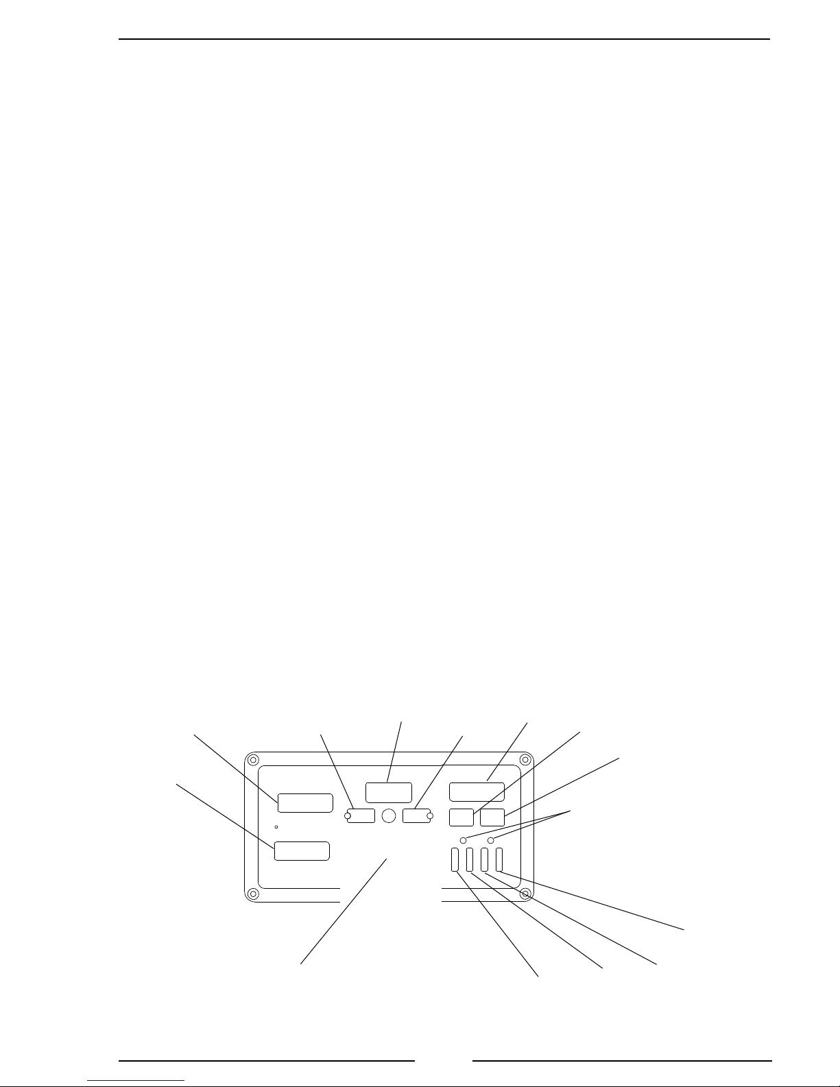
Controls and Indicators
All controls and indicators are located on the front of the control module. (Refer to
Figure 1.) Displays and LED brightness automatically adjusts for day or night operation.
PUMP DISCHARGE and PUMP INTAKE Displays
Shows the pump discharge and intake pressures during normal operations.
Message Display
The message display shows the pressure or RPM setting during normal operations
and warning alarms as they occur. It shows the time and date when the throttle ready
LED is off. It also shows stored data and program features.
PRESSURE Button and LED
Selects the pressure mode of operation, the LED is on to indicate operation in the
pressure mode.
RPM Button and LED
Selects the RPM mode of operation, the LED is on to indicate operation in the
RPM mode.
THROTTLE READY LED
This LED is on when the required interlock conditions are met and the governor
is ready to begin pump operations.
IDLE Button
When pressed immediately sets the engine RPM to idle. This button can be used
in an emergency or for normal shutdown after operations.
PRESET Button
Press to change/select a pre-programmed value for pressure or RPM setting.
DEC / INC Buttons (TGA300 Only)
During operations the buttons increase and decrease pressure or RPM setting.
Control Knob (TGA400 Only)
When rotated changes the pressure or RPM setting. The setting will increase or
decrease proportionally to the speed and direction the control knob is rotated.
RPM Display
Shows the engine RPM during normal operations.
8
TGA300 Rev180405
SILENCE Button
Suppresses audio alarms. Used when accessing program features.
MENU Button
Used to access detailed information and program features. The detailed information
includes the exact measure and units for monitored functions. Each time the MENU
button is pressed the display scrolls to show the next value
CHECK ENGINE / STOP ENGINE LEDs
Repeats the engine warnings from the cab.
Engine Oil Pressure LED Display
Shows pressure in safe range with green LEDs. The LEDs ash red when the
pressure is low.
Engine Coolant Temperature LED Display
Shows temperature in safe range with green LEDs. The LEDs ash red when the
temperature is high.
Pump Transmission Temperature LED Display
Shows temperature in safe range with green LEDs. The LEDs ash red when the
temperature is high.
Battery Voltage LED Display
Shows voltage in safe range with green LEDs. The LEDs ash red when the voltage
is outside normal limits.
PUMP
DISCHARGE
Display
PUMP
INTAKE
Display
PRESSURE
Button and
LED
Message
Display
RPM
Button and
LED
RPM
Display
SILENCE
Button
MENU
Button
CHECK ENGINE/
STOP ENGINE
LEDs
TGA300: IDLE, PRESET, INC, and DEC buttons
Governor Controls
TGA400: Control Knob, IDLE and PRESET buttons.
Engine Oil
Pressure
Display
Temperature
Figure 1. Controls and Indicators
9
Engine
Display
Battery
Voltage
Display
Transmission
Temperature
Display
TGA300 Rev180405
INSTALLATION
When the governor is programmed at the factory there is a label on the governor
that species the engine type. If there is no label the engine type must be veried and/
or programmed.
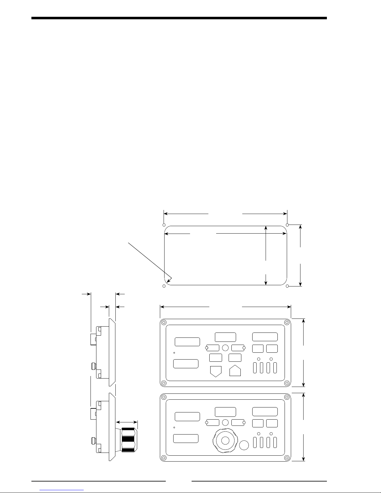
Install Control Module
1. Measure and mark mounting location for control module panel cutout and
mounting screw holes. Make sure there is clearance behind the panel for
the module and cables before cutting holes. Refer to Figure 2 for layout and
dimensions.
2. Cut out a 9 3/4 by 4 1/4 inch hole and drill four holes for mounting screws.
3. Place control module in position and secure with four screws (10-32 mounting
hardware is recommended).
4. Connect cables at rear of the control module. (Refer to Wiring Section.)
Mounting holes are
clearance or tapped
for 10-32 screws.
TGA300
Maximum
Radius
1/4"
2"
1/2"
9 3/4"
9 7/8"
Panel
Cutout
10 1/2"
4 7/8"
4 1/4"
5 1/2"
1 3/4"
TGA400
Figure 2. Control Module Mounting Dimensions
5 1/2"
10
TGA300 Rev180405
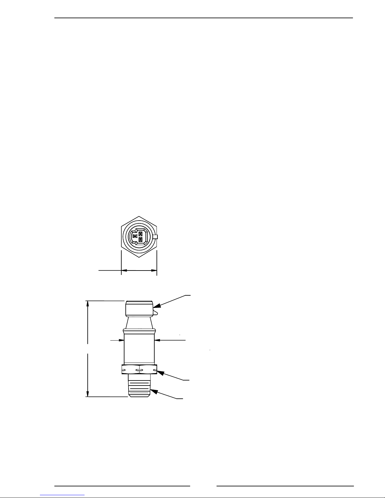
Install Pressure Sensors
Two pressure sensors are mounted on the pump manifolds, one on the discharge
and one on the intake. If there is a check valve in the discharge side of the pump,
mount the discharge sensor before the check valve. T-ttings can be used to mount
the pressure sensors.
Note: Install the pressure sensor upright so that water in the end of the pressure
sensor is able to drain back into the pipe.
1. Screw the sensor into a 1/4-18 NPT hole.
Caution: Do not use the main body that houses the electronics to tighten the
pressure sensor. Damage to the sensor may occur.
2. Tighten the sensor with a 7/8 inch wrench on the lower hex tting.
3. Connect the pressure sensor cable from the control module to the pressure
sensor. (Refer to Wiring Section.)
0.87 [22.05]
Across Flats
2.37 [60.30]
Caution: Do not use the main
body that houses the electronics
to tighten the sensor. Damage to
the sensor may occur.
Packard
Metri Pack
Connector
0.75 [18.95]
7/8" Hex
1/4-18 NPT
Inch [mm]
Figure 3. Pressure Sensor Dimensions
Caution: The discharge and intake
pressure sensors are the same size.
Ensure the correct sensor is installed on
the correct manifold. Refer to Table 1.
11

TGA300 Rev180405
Install Sensors
The information available on the J1939 databus varies depending on the particular
engine type. The sensors (if any) that need to be installed will also vary depending on
the engine.
The sensors are wired to the optional 6-pin connector at the rear of the control
module. Refer to the Wiring Section for connector pinout and wiring information.
Install Buzzer
Install the buzzer close to the control module so the audible warning is easily
associated with the visual warning on the display.
The optional buzzer provided by FRC requires a cutout hole of 1-1/8" (1.125").
Pin 7 on the 8-pin connector at the rear of the control module is used to connect
the buzzer. Connect the ground side of the buzzer to pin 7. (Maximum current through
pin 7 is 300 mA.) Refer to the Wiring section (Figure 5).
Install High-Idle Kit
The high-idle is activated when +12 VDC is provided to pin 4 (High-Idle Active
Input) of the 8-pin connector and to pin 3 (Interlock Input) of the 12-pin connector.
Refer to High-Idle Wiring.
Note: It is important that the connection to the Interlock Input from the
High-Idle circuit be isolated from the apparatus interlock wiring with the
two diodes. The pump must NOT be engaged when using the high-idle
function and the THROTTLE READY LED will be off.
Install Remote Governor Option
Refer to Install Control Module for dimensions. The remote governor is connected
to power, the J1939 CAN Bus, and the FRC datalink. Refer to Wiring Section.
Note: Program code P303 SYS TYPE must be set to REMOTE in the
remote governor program.
12

TGA300 Rev180405
OPERATION
Note: When power is applied to the governor the message display shows the
Software Program Revision Number for ve (5) seconds. It can also be viewed
with P101 code, refer to Programming Section.
On power up the governor is in the pressure mode of operation. The RPM display shows
engine RPM, the four LED bar graphs are green indicating readings within normal ranges,
and the message display will alternate between showing the date and time.
If a monitored function is not within normal parameters the display ashes, the RPM
display shows an error or fault warning code and a description shows in the message display.
(Refer to Table 2. Error Codes or Table 3. Fault Warning Codes.)
If one of the inputs displayed by the LED bar graphs is not within normal range the
LEDs will be red and ashing.
When all necessary throttle enables are active and the interlock circuit is complete, the
THROTTLE READY LED lights and the governor is ready to control the engine RPM.
Controls
INC/DEC Buttons (TGA300 Only)
The INC and DEC buttons are used to change pressure and RPM settings or program
preset values. The rate and amount the numbers change when a button is pressed depends
on the mode and how long the button is held.
Pressure Mode. Press either button momentarily to change the pressure setting by
1 PSI. Press and hold the button for more than 2 seconds and the pressure setting
changes by 5 PSI twice, then by 10 PSI until the button is released.
RPM Mode. Press either button momentarily to change the RPM setting by 10 RPM.
Press and hold the button for more than 2 seconds and the RPM setting changes by
50 RPM twice, then by 100 RPM until the button is released.
Control Knob (TGA400 Only)
The control knob is used to adjust pressure and RPM settings. The governor senses
how fast and in what direction the control knob is rotated and send a signal to the ECM to
increase or decrease the engine RPM proportionally.
If the control knob is rotated quickly; the engine RPM changes quickly.
If the control knob is rotated slowly; the engine RPM changes slowly.
• Rotate the control knob clockwise* to increase engine RPM.
• Rotate the control knob counterclockwise* to decrease engine RPM.
• Press the red IDLE button to immediately return the engine to idle.
*NOTE: Opposite knob rotation option is available to increase/decrease the
engine RPM.
13
TGA300 Rev180405
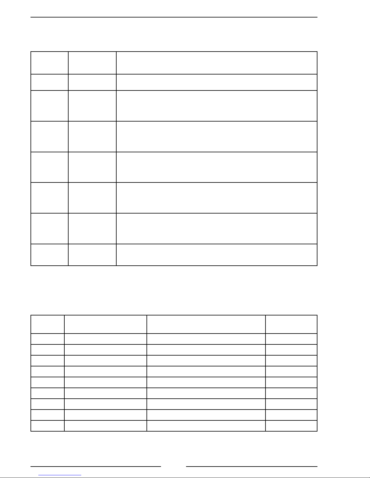
Error Codes and Fault Warnings
Table 2. Error Codes
RPM
Display
Message
Display
E01 NO DATA
E02 NO RPM
E04 NO OIL
SENSOR
E05 NO D. PSR
SENSOR
E06 NO I. PSR
SENSOR
E07 NO ENG T
SENSOR
E16 NO FRC
DATALINK
Probable Cause
Note: Not all inputs are used for all engines.
>J1939 CAN bus cable not connected / connected to wrong port
>Broken wire / bad connector contact on cable
Engine RPM not detected
>Data cable not connected / connected to wrong port
>Engine not running / ignition key on
>Broken wire / bad connector contact on alternator cable
No Engine Oil Pressure Data Detected (w/separate sensor input)
>Sensor cable not connected
>Broken wire / bad connector contact on sensor cable
>Defective pressure sensor
No Discharge Pressure Sensor Detected
>Sensor cable not connected
>Broken wire / bad connector contact on sensor cable
>Defective pressure sensor
No Intake Pressure Sensor Detected
>Sensor cable not connected
>Broken wire / bad connector contact on sensor cable
>Defective pressure sensor
No Coolant Temperature Data Detected (w/separate sensor input)
>Sensor cable not connected
>Broken wire / bad connector contact on sensor cable
>Defective temperature sensor
>FRC datalink cable not connected / connected to wrong port
>Broken wire / bad connector contact on cable
Note: E5 and E6 show on a remote governor not programmed correctly (code P303).
Table 3. Fault Warning Codes
RPM
Display
F01 HI BATT VOLTAGE
F02 LOW BATT VOLTAGE
F03 HI TRANS TEMP
F04 LOW OIL PRESSURE
F05 DPFR
F06 IPFR
F07 HI ENG TEMP
F08 NO WATER
F09 ENG NOT RESPOND
Message Display Description Factory
Default Setting
High Battery Voltage 15.5 V
Low Battery Voltage 11.8 V*
High Transmission Temperature 300 °F
Low Engine Oil Pressure 8 PSI**
Discharge Sensor High Voltage
Intake Sensor High Voltage
High Engine Coolant Temperature 220 °F**
Out of Water Mode
Engine Does Not Respond
* 11.8 engine running, 11.7 engine off.
** J1939 compliant—engine ECM will issue this warning.
14

TGA300 Rev180405
Pressure Mode Operation
In the pressure mode of operation the PRESSURE LED is on. The governor
maintains a constant discharge pressure within system capabilities. It adjusts the engine
RPM automatically to compensate for variations in pressure.
There is a maximum engine RPM programmed in the governor for pressure mode.
If the engine reaches the programmed maximum RPM the message display ashes MAX
RPM / OPERATOR and the engine RPM is not allowed to go higher. (The maximum
engine RPM is normally set at 2100 and is programmable.)
If the discharge pressure is below 15 PSI when the operator increases the pressure
setting, the display shows PRESS LOW.
Note: When changing from RPM to pressure mode during operations, hold
the PRESSURE button for 3 seconds. The pressure setting is the pressure
that the pump was operating at in RPM mode.
1. Press PRESSURE button to select the pressure mode.
Result: PRESSURE LED goes on.
2. Press PRESET and/or INC/DEC or rotate the control knob to select pressure
setting.
Result: Message display shows pressure setting, engine RPM changes.
3. Press IDLE button after operations to bring engine to idle RPM.
Result: Message display shows IDLE ENGINE, engine at idle RPM.
Opening/Closing Discharge Valves
In pressure mode the governor maintains the pressure setting regardless of the
number of discharge lines that are opened or closed providing there is sufcient water
supplied. As lines are opened the discharge pressure starts to drop, and the governor
raises the engine RPM to maintain the required pressure. As lines are closed and the
discharge pressure starts to rise, the governor lowers the engine RPM to maintain the
required pressure.
Operating From a Pressurized Supply
When operating from a pressurized water source (hydrant, in-relay, etc.), the intake
supply should be routed through a valve. If the pressurized source fails, the pump
operator can close the valve. This eliminates the chance of sharp pressure spikes at
the pump intake if the supply is resumed suddenly. The operator must open this valve
slowly when the supply is resumed to help prevent pressure spikes.
Note: The following description Running Away From Water, Low Water,
or No Supply Water is for software with a revision number V500.03 and
newer. Prior revisions should be updated. (Refer to Programming Section
to view the software revision number.)
15

TGA300 Rev180405
Running Away From Water, Low Water, or No Supply Water
There are situations during pump operations when there may be low or no supply
water. This can be due to an empty water tank, a problem on the intake line, air in the
pump, changing the water source, or an insufcient water supply.
The governor constantly monitors discharge pressure and compares it to engine
RPM. It is programmed to limit RPM increases when conditions arise that fall outside
of normal operating parameters.
Running Away From Water: If the discharge pressure starts dropping while
operating in pressure mode, the governor increases the engine RPM and attempts to
maintain the selected pressure setting. If pressure drops and an increase in RPM does
not bring the pressure back up, the governor recognizes this as a running away from
water condition. When this condition occurs the governor switches to the RPM limit
mode and controls the engine RPM accordingly.
RPM Limit Mode: When the RPM limit mode is in effect the PRESSURE
LED stays on. To alert the operator the RPM LED and the RPM display ash, and the
message display ashes OPERATOR / RPM LIMIT. In this mode the pressure setting
does not change and the PRESET button is disabled. When the pressure comes back
up to the selected pressure setting, the RPM limit mode is canceled and the governor
switches to normal operation in pressure mode at the selected pressure.
In some cases the pressure may not come back up but remains at a level above 45
PSI. In the RPM limit mode, the governor behaves like a manual throttle and the operator
can raise or lower the engine RPM by pressing INC/DEC or rotating the control knob.
If the RPM is manually lowered to a point where the pump is not running away from
water and pressure is stable, the RPM limit mode is canceled. The governor switches
to normal operation in pressure mode with the current discharge pressure as the new
pressure setting.
If the engine is set to idle using the IDLE button, the governor comes out of RPM
Limit Mode and cancels the pressure setting.
Low Water Cycle: If the discharge pressure is below 45 PSI, but stays above 15
PSI, the governor enters a low water cycle and the message display ashes LO WATER.
It sets the engine at 1100 RPM. If the pressure does not rise above 45 PSI in 7 seconds,
the governor sets the engine RPM at idle. The governor repeats the low water cycle as
long as the discharge pressure is between 15 and 45 PSI. When the pressure rises above
45 PSI the governor resumes normal operation. (The values for RPM and PSI in the
low water cycle are programmable and may vary for some engine/pump combinations.)
No Supply Water: If the discharge pressure is below 15 PSI, the engine RPM
is set at idle and the message display ashes NO WATER. If, within 3 minutes, the
discharge pressure rises above 15 PSI the governor enters the low water cycle. If the
discharge pressure does not rise above 15 PSI within 3 minutes, the governor switches
to idle mode and cancels the pressure setting. To restart pump operations, the operator
must take action (press PRESET and/or INC/DEC or rotate control knob to select
pressure setting).
16
 Loading...