

Frauscher Sensortechnik GmbH WSC001 Technical Documentation Manual

D4586-1
Technical documentation
Wheel sensor Signal Converter
WSC001
Frauscher Sensortechnik GmbH
Gewerbestraße 1 | 4774 St. Marienkirchen | Austria
Tel. +43 (0) 7711 2920-0 | Fax +43 (0) 7711 2920-25
office@frauscher.com | www.frauscher.com
Name
Signature
Date
Technical documentation
Wheel sensor Signal Converter
WSC001
Classified
Prepared:
Manuela Kothbauer
sign. Kothbauer
2017-03-31
Checked:
David Schön
sign. Schön
2017-03-31
D4586-1
Released:
Martin Rosenberger
sign. Rosenberger
2017-03-31
EN
1 / 58
© Frauscher Sensortechnik GmbH – All rights reserved. The reprinting, reproduction, storage on or in any data media or in any retrieval system, even if only in the form of extracts,
or the transfer to third parties, is only permitted with the express written consent of Frauscher Sensortechnik GmbH.

Classified
Technical documentation Wheel sensor Signal Converter WSC001
D4586-1
EN
- 2 -
© 2017 by Frauscher Sensortechnik GmbH – Austria
Masthead
Copyright 2017 by Frauscher Sensortechnik GmbH – Austria
The content of this documentation may not be reproduced in any form, either partially or as a
whole, nor disclosed to third parties without prior written consent of Frauscher.
All trademarks or registered trademarks mentioned herein are property of their respective owners.
All rights reserved.
Your opinion matters
With your comments and suggestions you assist us in our intention to continuously improve the
quality and practical relevance of the documentation.
Please send your suggestions for improvement to: documentation@frauscher.com
Thank you for your feedback.

Classified
Technical documentation Wheel sensor Signal Converter WSC001
D4586-1
EN
- 3 -
© 2017 by Frauscher Sensortechnik GmbH – Austria
Table of contents
Review list....................................................................................................................................... 6
Bibliography .................................................................................................................................... 6
List of standards ............................................................................................................................. 7
1 About this documentation ............................................................... 8
1.1 Typographical conventions.............................................................................................. 8
1.1.1 Pictograms ...................................................................................................................... 8
1.1.2 Styles of writing and other formal principles .................................................................... 8
1.2 Units of measurement ..................................................................................................... 9
1.3 Abbreviations ................................................................................................................ 10
1.4 Terms and definitions .................................................................................................... 12
1.5 Target group ................................................................................................................. 14
2 Safety .............................................................................................. 15
2.1 General protective provisions ........................................................................................ 15
2.2 Qualified personnel ....................................................................................................... 15
2.3 Safety-conscious working.............................................................................................. 15
2.4 Intended use ................................................................................................................. 16
3 Structure and function ................................................................... 17
3.1 Front panel elements and function ................................................................................ 17
3.2 Interfaces ...................................................................................................................... 20
3.2.1 Diagnostic interface “Serial Interface” ........................................................................... 22
3.2.2 Interface “wheel sensor” ................................................................................................ 22
3.2.3 Interface “power supply” ................................................................................................ 23
3.2.4 Interfaces “optocoupler outputs” .................................................................................... 25
4 Basic conditions for the installation ............................................. 26
4.1 Environmental conditions .............................................................................................. 26

Classified
Technical documentation Wheel sensor Signal Converter WSC001
D4586-1
EN
- 4 -
© 2017 by Frauscher Sensortechnik GmbH – Austria
4.2 Electromagnetic compatibility ........................................................................................ 26
5 Configuration.................................................................................. 27
5.1 General setting of the DIP-switches .............................................................................. 27
5.2 DIP-switches of the WSC .............................................................................................. 28
5.2.1 Configuration of system outputs and/or direction outputs .............................................. 29
5.2.1.1 Configuration with 1 wheel sensor RSR110-001 ........................................................... 30
5.2.1.2 Configuration with 1 wheel sensor RSR110-001 or 2 wheel sensors RSR110-002 ....... 30
5.2.1.3 Configuration with 1 wheel sensor RSR110-001 or 1 wheel sensor RSR110-002 ......... 31
5.2.2 Configuration of the normal status of all optocoupler outputs ........................................ 31
5.2.3 Configuration of the system output extension time ........................................................ 33
5.2.4 Configuration of the direction pulse duration ................................................................. 34
6 Signal diagrams ............................................................................. 35
6.1 Switching times and switching levels ............................................................................. 35
6.2 Traversings ................................................................................................................... 36
6.2.1 Correct traversing of one wheel .................................................................................... 36
6.2.2 Traversing of one wheel without overlap ....................................................................... 38
6.3 Behaviour in case of wire break .................................................................................... 39
6.4 Behaviour in case of overcurrent ................................................................................... 40
7 Installation ...................................................................................... 41
7.1 Wiring of the Wheel sensor Signal Converter WSC ....................................................... 41
7.2 Mounting and dismounting of the WSC ......................................................................... 44
8 Commissioning .............................................................................. 45
8.1 Adjustment .................................................................................................................... 45
8.1.1 Adjustment by using the AMB ....................................................................................... 45
8.1.2 Adjustment by means of the DIP-switch with DIP-no. 8 ................................................. 46
8.2 Data request with Advanced Service Display ASD ........................................................ 47
8.2.1 “INFO” tab ..................................................................................................................... 48
8.2.2 “STATUS” tab ............................................................................................................... 49

Classified
Technical documentation Wheel sensor Signal Converter WSC001
D4586-1
EN
- 5 -
© 2017 by Frauscher Sensortechnik GmbH – Austria
8.2.3 “STATISTICS” tab ......................................................................................................... 50
9 Maintenance ................................................................................... 51
9.1 Required measuring equipment and tools ..................................................................... 51
9.2 Visual inspection and mechanical check of the wheel sensor ................................ ........ 51
9.3 Check of the sensor currents of the wheel sensor ......................................................... 52
9.4 Check of the occupancy detection capability ................................................................. 52
10 Repair .............................................................................................. 54
10.1 Troubleshooting of the WSC ......................................................................................... 54
10.1.1 LED indications on the WSC ......................................................................................... 54
10.1.2 Measurements on the WSC with connected wheel sensor RSR110 .............................. 57
11 Removal from service .................................................................... 58

Classified
Technical documentation Wheel sensor Signal Converter WSC001
D4586-1
EN
- 6 -
© 2017 by Frauscher Sensortechnik GmbH – Austria
Version
Date
Prepared by
Sections modified
Modifications
1
2017-03-31
Manuela Kothbauer
all
initial version
D-Number
Title
Version1
D2860
Brief instruction testing plate PB200 GS03
4
D4231
Mounting, commissioning and maintenance manual wheel sensor
RSR110
1
D4232
Application guide wheel sensor RSR110
1
D21004
Brief description Advanced Service Display ASD101
2
1
Review list
Bibliography
The stated or a higher version is valid.

Classified
Technical documentation Wheel sensor Signal Converter WSC001
D4586-1
EN
- 7 -
© 2017 by Frauscher Sensortechnik GmbH – Austria
Number
Title
Issue/
version
DIN EN 60715
Dimensions of low-voltage switchgear and controlgear
Standardized mounting on rails for mechanical support
of electrical devices in switchgear and controlgear
installations
2001
EN 50121-4
Railway applications – Electromagnetic compatibility –
Part 4: Emission and immunity of the signalling and
telecommunications apparatus
2015
EN 50124-1
Railway applications – Insulation coordination – Part 1:
Basic requirements – Clearances and creepage distances for all electrical and electronic equipment
2006
EN 50125-3
Railway applications – Environmental conditions for
equipment – Part 3: Equipment for signalling and telecommunications
2003
EN 50128
Railway applications – Communication, signalling and
processing systems – Software for railway control and
protection systems
2011
EN 60529
Degrees of protection provided by enclosures (IP Code)
2014
EN 60721-3-1
Classification of environmental conditions – Part 3:
Classification of groups of environmental parameters
and their severities – Section 1: Storage
1997
EN 60721-3-2
Classification of environmental conditions – Part 3:
Classification of groups of environmental parameters
and their severities – Section 2: Transportation
1997
EN 60721-3-3
Classification of environmental conditions – Part 3:
Classification of groups of environmental parameters
and their severities – Section 3: Stationary use at
weatherprotected locations
1995
List of standards
-1
125-3
60721-3-2
1 About this documentation
Classified
Technical documentation Wheel sensor Signal Converter WSC001
D4586-1
EN
- 8 -
© 2017 by Frauscher Sensortechnik GmbH – Austria
Description
1 About this documentation
This documentation provides information about the product features and the required information
for the configuration and installation of the Wheel sensor Signal Converter WSC001.
1.1 Typographical conventions
The following typographical conventions are applied in this documentation:
1.1.1 Pictograms
Important notes
Important notes contain information and instructions regarding the availability and the safe operation of the system.
Important information and notes are shown as follows:
1.1.2 Styles of writing and other formal principles
Orders
• Contents (descriptions, figures, tables etc.) are generally described in this documentation “from
left to right” and “from top to bottom”.
Numbers
• Decimal places of decimal numbers are separated by a comma (,) (e.g.: 123,45).
• For reasons of better readability, digits of four- or multi-figure decimal numbers are arranged
from right to left with thousands separators in groups of three digits (e.g. 1 234).

1 About this documentation
Classified
Technical documentation Wheel sensor Signal Converter WSC001
D4586-1
EN
- 9 -
© 2017 by Frauscher Sensortechnik GmbH – Austria
1.2 Units of measurement
In this documentation the following units of measurement are used:
bit bit
°C degree in Celsius (degree in Fahrenheit °F = °C * 1,8 + 32)
m metre (yard = m * 1,09361)
mA milliampere
mm millimetre (inch = mm * 0,0393701)
ms millisecond
Ω ohm
s second
V volt

1 About this documentation
Classified
Technical documentation Wheel sensor Signal Converter WSC001
D4586-1
EN
- 10 -
© 2017 by Frauscher Sensortechnik GmbH – Austria
1.3 Abbreviations
In this documentation the following abbreviations are used:
0b prefix of a binary number
0x prefix of a hexadecimal number
A measurement A, vertical mounting position of the wheel sensor
AEI Automatic Equipment Identification
AMB Adjustment and Maintenance Box
ASD Advanced Service Display
B measurement B, horizontal mounting position of the wheel sensor
DC direct current
DIN German Institute for Standardization
DIP Dual In-line Package (DIP-switch)
EMC electromagnetic compatibility
EN European standard
GAK trackside connection box
GND ground
GS equipment version
IEC International Electrotechnical Commission
IPxx International Protection (protection type, e.g. IP65)
LED light-emitting diode
PB testing plate
PWR Power supply
Ri direction pulse of a traversing
Ri1 direction pulse, direction 1
Ri2 direction pulse, direction 2

1 About this documentation
Classified
Technical documentation Wheel sensor Signal Converter WSC001
D4586-1
EN
- 11 -
© 2017 by Frauscher Sensortechnik GmbH – Austria
RJ45 Registered Jack (standardised connectors/sockets for data transmission in
networks)
RSR wheel sensor
RSR110 wheel sensor, type RSR110
SIL Safety Integrity Level
SPS Programmable Logic Controller (PLC)
Sys system pulse
Sys1 system pulse of sensor system 1
Sys2 system pulse of sensor system 2
SYS1 sensor system 1
SYS2 sensor system 2
USB Universal Serial Bus
WSC Wheel sensor Signal Converter

1 About this documentation
Classified
Technical documentation Wheel sensor Signal Converter WSC001
D4586-1
EN
- 12 -
© 2017 by Frauscher Sensortechnik GmbH – Austria
1.4 Terms and definitions
commissioning Test on an item carried out on site, to prove that it is
correctly installed and can operate correctly
(IEC 60050-151-16-24).
damped One or two sensor systems of a wheel sensor indi-
cate an occupancy (generally in the case of traversing by a train wheel and/or when damped by a testing
plate).
digital filtering time The digital filtering time is the time for which the
sensor current must fall below the trigger level or exceed the tripping level, before the sensor system is
considered to be “damped” or “not damped”.
direction pulse duration The direction pulse duration is the time for which the
direction pulse applies at the output. The direction
pulse duration is retriggerable.
interference voltage Voltage that may occur at the ends of outdoor
equipment cables as a result of inductive or capacitive influences to earth.
maintenance, corrective The maintenance carried out after fault recognition
and intended to put an item into a state in which it
can perform a required function
(IEC 60050-191-07-08).
Synonym: repair
maintenance, preventive The maintenance carried out at predetermined inter-
vals or according to prescribed criteria and intended
to reduce the probability of failure or the degradation
of the functioning of an item (IEC 60050-191-07-07).
Synonym: servicing
maintenance, servicing The maintenance carried out at predetermined inter-
vals or according to prescribed criteria and intended
to reduce the probability of failure or the degradation
of the functioning of an item (IEC 60050-191-07-07).
Synonym: preventive maintenance

1 About this documentation
Classified
Technical documentation Wheel sensor Signal Converter WSC001
D4586-1
EN
- 13 -
© 2017 by Frauscher Sensortechnik GmbH – Austria
normal operating sensor current level The normal operating sensor current level corre-
sponds to the sensor current at the time of a successfully carried out adjustment and is to be equated
with 100 % (adjustment value).
normal operating sensor current (RSR110) The sensor current is referred to as “normal operat-
ing sensor current” if the wheel sensor is correctly
mounted on the rail, successfully adjusted and not
damped.
overcurrent level If the sensor current exceeds the overcurrent level for
the time > overcurrent suppression time, then the
evaluation board identifies the behaviour as “overcur-
rent”.
overcurrent suppression time The overcurrent suppression time is the minimum
time for which the sensor current must exceed the
overcurrent level, so that the evaluation board identifies the behaviour as “overcurrent”. The sensor sys-
tem is then considered to be “faulty”.
overlap “Overlap” means that both sensor systems are
damped.
repair The maintenance carried out after fault recognition
and intended to put an item into a state in which it
can perform a required function
(IEC 60050-191-07-08).
Synonym: corrective maintenance
system output delay time The system output delay time is the time, which
passes after the digital filtering time until the switching operation at the system output, when the sensor
current falls below the trigger level.
system output extension time The system output extension time is the time, which
passes after the digital filtering time until the switching operation at the system output, when the sensor
current exceeds the tripping level. The system output
extension time is retriggerable.
top-hat rail rail with hat-shaped cross-section according to
DIN EN 60715, type TH 35-7.5, perforated

1 About this documentation
Classified
Technical documentation Wheel sensor Signal Converter WSC001
D4586-1
EN
- 14 -
© 2017 by Frauscher Sensortechnik GmbH – Austria
trigger level If the sensor current falls below the trigger level for
the time > digital filtering time, then the sensor system is considered to be “damped”.
tripping level If the sensor current exceeds the tripping level for the
time > digital filtering time, then the sensor system is
considered to be “not damped”.
wire break level If the sensor current falls below the wire break level
for the time > wire break suppression time, then the
evaluation board identifies the behaviour as “wire
break”.
wire break suppression time The wire break suppression time is the minimum time
for which the sensor current must fall below the wire
break level, so that the evaluation board identifies the
behaviour as “wire break”. The sensor system is then
considered to be “faulty”.
wire short-circuit level If the sensor current exceeds the wire short-circuit
level for the time > overcurrent suppression time,
then the evaluation board identifies the behaviour as
“wire short-circuit”.
1.5 Target group
This documentation is intended for project engineers and technicians with subject-specific
knowledge who are responsible for configuration, installation, commissioning, operation and
maintenance of Frauscher components.
2 Safety
Classified
Technical documentation Wheel sensor Signal Converter WSC001
D4586-1
EN
- 15 -
© 2017 by Frauscher Sensortechnik GmbH – Austria
The component described in this documentation must only be used for non-safetyrelevant applications.
All operational protective provisions of the rail operator must be observed.
The railway operator must ensure that only authorised personnel or people in the company of authorised personnel have access to Frauscher components.
Prior to and during works on the track, safety measures must be carried out according
to the applicable railway regulations.
Working on Frauscher components (configuration, installation, commissioning and
maintenance) must only be carried out by trained and skilled personnel.
2 Safety
This documentation contains important warning and safety information, which must be observed by
the user. Only by compliance with these prerequisites and safety measures, a correct operation
can be ensured.
2.1 General protective provisions
Frauscher components must be used in the original condition (= characteristics and functions as
described in the respective documentation).
Only the settings described in the respective documentation may be carried out. Apart from that,
arbitrary changes of the components are not permitted.
However, if changes of a component should be required, then Frauscher must be consulted in any
case and in advance.
2.2 Qualified personnel
2.3 Safety-conscious working
• The railway operator is responsible for occupational safety.
• Frauscher components may only be operated in proper condition.
• All actions carried out on Frauscher components must not impair the safety of people or the
function of the system.
• Unauthorized alterations and modifications must not be carried out on Frauscher components.

2 Safety
Classified
Technical documentation Wheel sensor Signal Converter WSC001
D4586-1
EN
- 16 -
© 2017 by Frauscher Sensortechnik GmbH – Austria
2.4 Intended use
The product is intended for a specific operation purpose described in the documentation. If applied
outside the intended use described, in the case of non-compliance with the documentation or in the
case of non-compliance with required prerequisites and safety measures, no warranty and/or
liability shall apply.
3 Structure and function
Classified
Technical documentation Wheel sensor Signal Converter WSC001
D4586-1
EN
- 17 -
© 2017 by Frauscher Sensortechnik GmbH – Austria
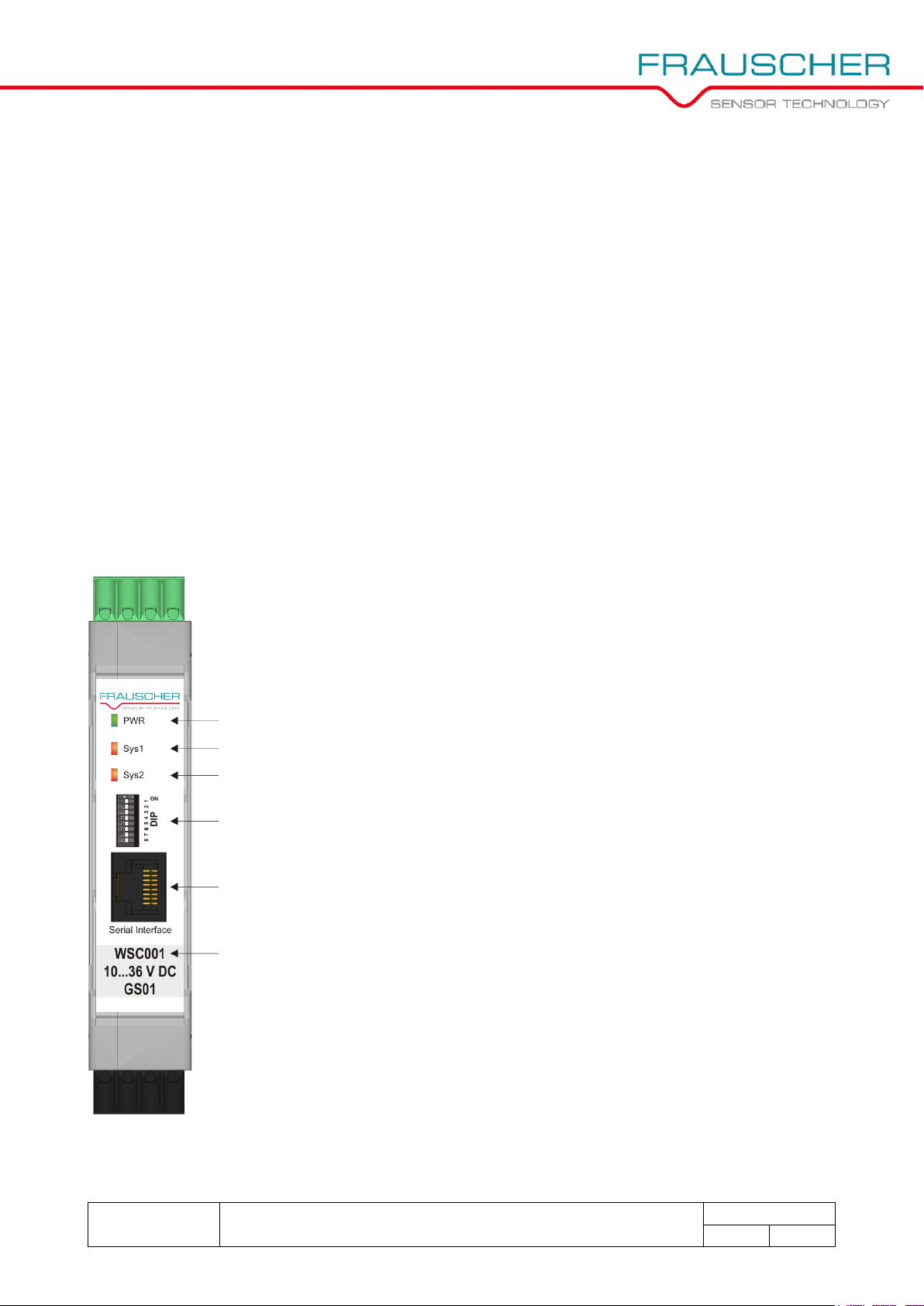
Element
Description
PWR (LED)
status indicator of the power supply
Sys1 (LED)
status indicator of sensor system 1
Sys2 (LED)
status indicator of sensor system 2
DIP-switches
configuration of the outputs and
adjustment of the wheel sensor via WSC
Serial Interface
(RJ45-socket)
connection socket for diagnostic interface
(Advanced Service Display ASD)
Type key:
WSC001
board identification
10…36 V DC
permissible supply voltage
GSxx
equipment version (starting at 01)
3 Structure and function
The WSC in combination with the wheel sensor RSR110 provides outputs that are triggered by a
passing wheel of a rail vehicle.
Examples of possible applications:
• trigger for AEI card reader
• trigger for lubrication system
• trigger for hot box detection system
• trigger for vision monitoring system
• trigger for warning system
• trigger for flat wheel detection system
3.1 Front panel elements and function
The front panel of the WSC is designed as follows:
Figure 3.1: Front panel of the WSC
3 Structure and function
Classified
Technical documentation Wheel sensor Signal Converter WSC001
D4586-1
EN
- 18 -
© 2017 by Frauscher Sensortechnik GmbH – Austria
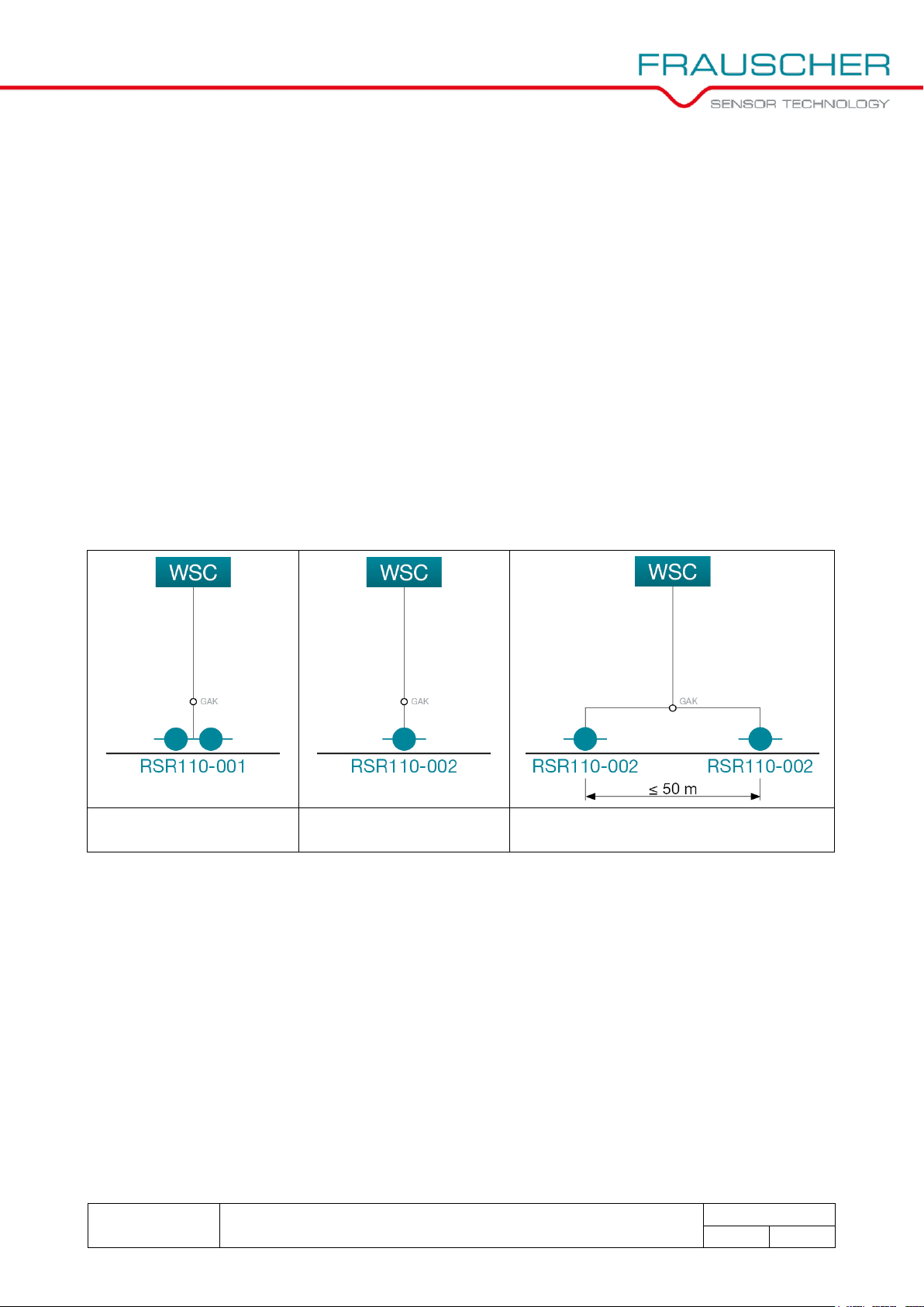
WSC combined with
1 RSR110-001
WSC combined with
1 RSR110-002
WSC combined with
2 RSR110-002
The WSC complies with the requirements of SIL 0 according to EN 50128.
The WSC processes the wheel sensor information of the wheel sensors RSR110-001 and
RSR110-002.
The wheel sensor RSR110-001 is equipped with 2 sensor systems and can output the status of
the sensor systems (damped, not damped or faulty) and the travel direction.
The wheel sensor RSR110-002 is equipped with 1 sensor system and can output the status of the
sensor system (damped, not damped or faulty).
The WSC can be combined with:
• 1 wheel sensor RSR110-001
• 1 wheel sensor RSR110-002
• 2 wheel sensors RSR110-002
Figure 3.2: Block diagrams with possible combinations of the WSC with RSR110-001 or RSR110-002
In order to limit the interference voltage, the distance between 2 wheel sensors RSR110-002 that
are connected to the same WSC must not exceed 50 m and the distance between the WSC and
the higher-ranking system must not exceed 30 m.
The WSC supplies the wheel sensors with voltage and converts the analogue signals of the wheel
sensors into digital signals. The digital signals are transmitted as digital switching signals to a
higher-ranking system via optocoupler outputs.
 Loading...