

Page 1
C-TSH
COMPRESSORI COMPATTI A DOPPIA VITE
COMPACT TWIN SCREW COMPRESSORS
KOMPAKTDOPPELSCHRAUBENVERDICHTER
Guida operativa
Application guide
Projektierungshandbuch
2003 11-01
Page 2

• FRASCOLD SpA si riserva il diritto di modificare
i dati e le caratteristiche contenute nel presente
catalogo, senza obbligo di preavviso.
FRASCOLD SpA reserves the right to change at
any time, specifications or design without notice
and without incurring obligations.
FRASCOLD SpA behält sich das Recht vor
Spezifikationen oder Ausführungen jederzeit ohne
Bekanntgabe zu ändern.
FTEC11-01
Ref: FTEC11-01
Edizione: Maggio 2003
sostituisce: FTEC11-00
Giugno 2001
Realizzazione: FRASCOLD SpA
2
Page 3

Indice
Index
Inhaltsverzeichnis
1. Descrizione generale
1.1 Caratteristiche salienti
1.2 Caratteristiche costruttive
2. Controllo di capacità
3. Fissaggio del compressore
4. Lubrificazione
4.1 Il separatore integrato
4.2 Raffreddamento dell’olio
5. Il lubrificante
5.1 Caratteristiche del lubrificante
5.2 Raccomandazioni
5.3 Lubrificanti miscelati, sostituzione
del lubrificante
6. Installazione, tubazioni frigorifere
6.1 Tubazioni frigorifere
7. Condizioni di impiego particolari
7.1 Iniezione di liquido
7.2 Avviamento in vuoto
7.3 Economizzatore
8. Motore elettrico
FTEC11-01
9. La protezione
10. Tavole, disegni, dati tecnici
1. General
1.1 Outstanding features
1.2 Construction features
2. Capacity control
3. Compressor fixing
4. Lubrication
4.1 Built-in oil separator
4.2 Oil cooling
5. The lubricant
5.1 Lubricant data
5.2 Recommendations
5.3 Lubricant mixing, oil
replacement
6. Compressor installation, piping
6.1 Piping
7. Special operative conditions
7.1 Liquid injection
7.2 Unloading start
7.3 Economizer
8. Electric motor
9. Compressor protection
10. Data tables, drawings, diagrams
1. Allgemeine
1.1 Herausragende Merkmale
1.2 Baumerkmale
2. Leistungsregelung
3. Aufstellung des Verdichter
4. Schmierung
4.1 Angeflanschten Ölabscheider
4.2 Ölkühlung
5. Schmiermittel
5.1 Schmiermitteleigenschaften
5.2 Ausführungshinweise
5.3 Gemischte Schmiermittel,
Ölwechsel
6. Verdichtersinstallation,
Rohrleitungen
6.1 Rohrleitungen
7. Besondere Systembedingungen
7.1 Flüssigkeitseinspritzung
7.2 Anlaufentlastung
7.3 Economizer
8. Elektromotor
9. Verdichterschutz
10. Daten, Tabellen, Zeichnungen,
Diagramme
3
Page 4

1. Descrizione generale
1. General
1. Allgemein
La nuova linea di compressori a doppia vite serie
C-TSH8 è disponibile in 16 modelli che coprono
un vasto campo di applicazioni da 12.5°C a -15°C,
adatti per refrigeranti R134a, R22, R407C (altri
refrigeranti a richiesta) e precisamente:
• 8 modelli C-TSH8 equipaggiati con motore
elettrico particolarmente adatto per impieghi
con refrigerante R134a; capacità volumetriche
da 120 m3/h a 360 m3/h con alimentazione
elettrica a 50Hz (da 144 m3/h a 432 m3/h
a 60Hz) e potenze installate da 22 kW a
74 kW (da 30 HP a 100 HP)
• 8 modelli C-TSH8 adatti per impieghi con
refrigeranti R22 e R407C; capacità
volumetriche da 120 m3/h a 360 m3/h con
alimentazione elettrica a 50Hz (da 144 m3/h
a 432 m3/h a 60Hz) e potenze installate da
30 kW a 89 kW (da 40 HP a 120 HP).
1.1 Caratteristiche salienti
• potenzialità e rendimenti elevati dovuti
principalmente a:
- geometria innovativa dei profili delle viti
con un rapporto 5:6 tra i denti della
vite maschio e quelli della vite femmina
- elevato rendimento del motore elettrico
- rapporto volumetrico intrinseco Vi ottimizzato
- lubrificazione calibrata delle viti
• costruzione meccanica accurata e semplice
• adeguata dotazione di cuscinetti a rulli e a
sfere per garantire un eccellente supporto
alla rotazione delle viti e alle sollecitazioni
assiali e radiali alle quali sono sottoposte
durante il funzionamento
• dispositivo per il controllo di capacità
efficiente e di semplice costruzione
• motore elettrico con avviamento frazionato
(PWS - Part Winding Start)
• basso livello sonoro e assenza di vibrazioni
• rapporto ingombro-potenza estremamente
favorevole
• peso contenuto
1.2 Caratteristiche costruttive
I compressori a vite C-TSH8 sono compressori
volumetrici rotativi a due alberi, con geometria
innovativa dei profili (rapporto 5:6).
I componenti essenziali di questi compressori
sono le due viti (vite maschio e vite femmina)
realizzate mediante rettifica e montate con
grande precisione nel carter viti.
Uno studio particolarmente accurato è stato
svolto per dimensionare e identificare la
configurazione e la sequenza di installazione
dei cuscinetti; il risultato è una rotazione delle
viti con attriti estremamente ridotti e il
mantenimento dell’allineamento delle viti
anche durante il funzionamento con condizioni
gravose (alta pressione di mandata,
avviamento e breve controrotazione all’arresto
del compressore).
The new range of C-TSH8 twin screw
compressors includes 16 models suitable for a
wide range of applications from 12.5°C to -15°C,
suitable for refrigerants R134a, R22, R407C (other
refrigerants on request), in details:
• 8 models C-TSH8 series, equipped with
electric motor specific for applications with
R134a; the displacement is from
120 m3/h up to 360 m3/h with 50 Hz power
supply (from 144 m3/h up to 432 m3/h with
60 Hz) with nominal power from 22 kW up
to 74 kW (from 30 HP to 100 HP)
• 8 models C-TSH8 series, suitable for
applications with refrigerants R22 and
R407C; the displacement is from
120 m3/h up to 360 m3/h with 50 Hz
power supply (from 144 m3/h up to
432 m3/h with 60 Hz) with nominal power
from 30 kW up to 89 kW (from 40 HP to
120 HP).
1.1 Outstanding features
• high performances and efficiency of
compressors C-TSH8 are mainly due to:
- exclusive design of screw profiles with
a ratio 5:6 between male screw and
female screw
- electrical motor with very high efficiency
- flowing through slots of the rotor, suction
gas is centrifugated for liquid separation
- optimized Vi volume ratio
- calibrated lubrication of the screws
• sturdy and simple design of mechanical
parts carefully manufactured
• the excellent combination of ball and roller
bearing gives excellent screw support
resulting in smooth rotation and reduced
axial and radial stresses during running
• simple and efficient capacity control device
• high efficiency electric motor with
Part-Winding start
• low noise level and smooth vibrationless
running
• excellent volume-capacity ratio
• lightweight
1.2 Construction features
C-TSH8 compressors are two shaft rotary
displacement design, with innovative profiles
of the screws (ratio 5:6).
Essential parts of C-TSH8 compressors are the
two screws (male screw and female screw)
manufactured by means grinding and assembled
with precision into the screw carter.
Particulare care has been taken with the bearing
design regarding size, type and location.
The result is greatly reduced friction and
accurate screw alignment during running even
under extreme conditions (high discharge
pressure, stops/start sequence with
consequent counter-rotation).
Die neue Schraubenbaureihe der C-TSH8
Doppelschraubenverdichter bietet 16 Modelle
für die Anwendungen von 12.5°C bis -15°C,
geeignet für Kältemittel R134a, R22, R407C
(andere Kältemittel auf Anfrage); im Detail:
• 8 C-TSH8 Modellen mit Elektromotor
geeignet für Anwendungen mit Kältemittel
R134a; Fördervolumen von 120 m3/h
bis 360 m3/h bei 50 Hz ( von 144 m3/h
bis 432 m3/h bei 60 Hz) und einer
nominalen Motorgröße von 22 kW bis
74 kW (30 PS bis 100 PS)
• 8 C-TSH8 Modellen, anwendbar
mit Kältemittel R22 und R407C; mit einem
Fördervolumen von 120 m3/h bis
360 m3/h bei Anschluß an das 50 Hz Netz
(144 m3/h bis 432 m3/h bei 60 Hz) mit
einer nominalen Motorgröße von 30 kW bis
89 kW (40 PS bis 120 PS).
1.1 Herausragende Merkmale
• Hohe Leistung und Wirtschaftlichkeit der
C-TSH8 Verdichter durch:
- perfekte Profilform mit Zahnverhältnis 5:6
- hohen Motorwirkungsgrad
- optimierte Vi Volumenverhältnis
- kalibrierte Ölversorgung der Schrauben
• Einfacher und sorgfältiger Aufbau
• die Ausstattung mit guten Kugel- und
Wälzlagern gewährleistet ruhige und
stressfreie Schraubendrehungen während
des Verdichterlaufes sowohl in axialer wie
auch in radialer Hinsicht
• Effiziente, einfache Leistungsregelung
• Elektromotor mit Teilwicklungsanlauf
• Niedriges Geräuschniveau und Abwesenheit
von Schwingungen
• Äußerst günstiger AbmessungenLeistungsverhältnis
• Niedriges Gewicht
1.2 Baumerkmale
Die C-TSH8 Schraubenverdichter sind
doppelschraube Verdränger in perfekte
Profilform (Verhältnis 5:6)
Die wichtigste Komponenten dieser Verdichter
sind die zwei Schrauben (Haupt- und
Nebenschraube) durch Schleifen realisiert und
genau im Schraubengehäuse montiert.
Größe, Art und Positionierung der Lager sowie die
Installationsweise wurden mit größter Sorgfalt
gewählt.
Das Ergebnis ist ein reduzierter Reibungsverlust und
eine akkurate Ausrichtung der Schrauben während
des Laufes in schwierigen Betriebs-bedingungen
(hoher V erflüssigungsdruck , Start und Stop-Betrieb
mit rückläufiger Drehrichtung).
Die Schmierung ist von einem großen Ölvorrat im
Gehäuse- Abscheider gevähren.
Alle Modelle sind komplett mit Internes
Sicherheitsventil.
FTEC11-01
4
Page 5
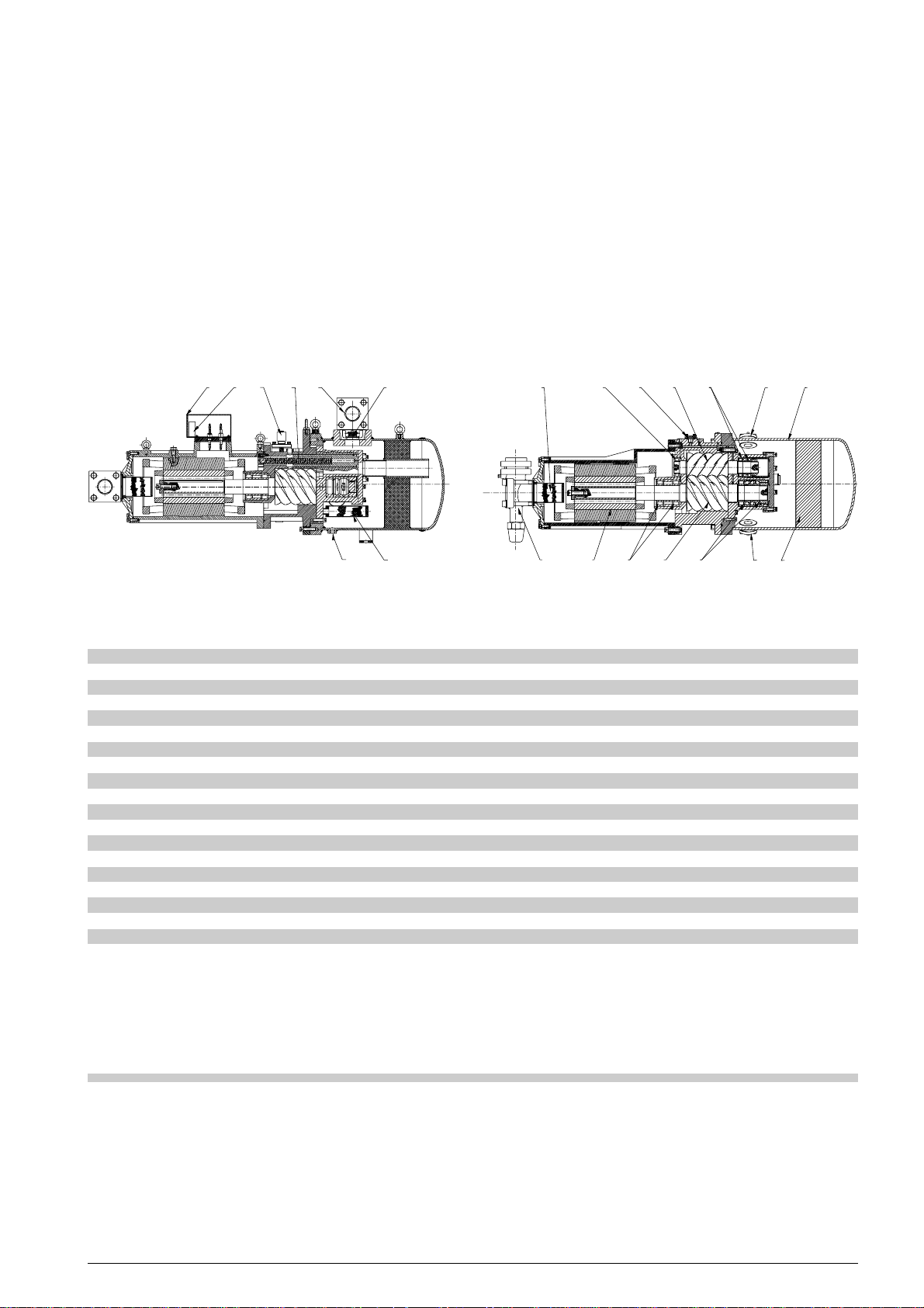
La lubrificazione è assicurata da una notevole
riserva di olio contenuta all'interno del carter separatore.
Tutti i modelli sono dotati di valvola di sicurezza
interna.
I compressori sono azionati da un motore
elettrico asincrono trifase bipolare alloggiato in
un carter , il tutto fissato a mezzo flangia al carter
delle viti.
Il rotore del motore elettrico è calettato
direttamente all'albero della vite maschio.
Il raffreddamento del motore avviene tramite il
gas aspirato che passando anche nei fori praticati
nel rotore, viene centrifugato e separato da
eventuali tracce di liquido.
The shafts are fitted with roller bearings sized
to bear both radial loads and axial loads also
when compressor stops and a reverse turning
takes place.
Electric motor is two pole, three phase
asynchronous type closely with the housing
joined to the screw carter.
Its rotor is closely fitted with the shaft of male
screw.
Cooling of electric motor is carried out by the
suction gas flowing through slots of the rotor.
Die Verdichter werden angetrieben von
2-poligen, dreiphasigen asynchronen
Elektromotoren, die in einem Gehäuse an das
Verdichtergehäuse angeflanscht sind.
Der Rotor des Motors ist direkt mit der männlichen
Schraube verbunden. Die Kühlung des
Elektromotors wird durch das Sauggas erreicht, das
durch die Nuten des Rotors geführt und durch die
zentrifugale Bewegung von möglichen flüssigen
Kältemittelpartikeln befreit wird.
14
6
17 8 12 3 9 2 3
11
16
10
18
5
4
fig. 1 fig. 1 Abb. 1
1 vite maschio male screw Hauptschrauber
2 vite femmina female screw Nebenschrauber
FTEC11-01
3 cuscinetti bearings Wälzlagerung
4 motore elettrico electric motor Elektromotor
5 rubinetto di aspirazione suction valve Saugventil
6 scatola terminali terminal box Elektrischer Anschlußkasten
7 filtro coalescente oil demister Ölabscheiderfilter
8 pistone del controllo di capacità capacity control piston Leistungsregelung
9 attacchi per raffreddatore olio esterno connections for remote oil cooler Ölkühleranschlüße
10 filtro olio oil strainer Ölfilter
11 rubinetto di compressione discharge valve Druckventil
12 filtro di aspirazione suction strainer Saugfilter
13 spia livello olio oil level sight glass Ölschauglas
14 modulo elettronico di protezione electronic module Elektronisches Auslösegerät
15 separatore d’olio integrato built in oil separator angeflanschten Ölabscheider
16 valvola di ritegno check valve Rückschlagventil
17 valvola controllo di capacità capacity control valve Leistungsregelungsventil
18 tappo scarico olio oil drain plug Ölablaß
15
13
13
3
713
2. Controllo di capacità
In condizioni di ridotto carico termico, il compressore
è in grado di portare la struttura da raffreddare alla
temperatura di progetto in un tempo più breve; in
tale caso è necessario verificare se l’aumentato
numero di avviamenti del compressore (che deriva
da un più breve periodo di raffreddamento) è
compatibile con il massimo che il compressore
può sopportare.
2. Capacity control
In case of reduced heat load, the compressor
is able to cool down the structure to the
project temperature in a shorter time; in this
case it is necessary to verify if the increased
number of compressor starts (due to a
shorter cooling period) is suitable
with the maximum acceptable for the
compressor.
5
2. Leistungsregelung
Im Falle einer Reduzierung des Leistungsbedarfs
kann der V erdichter die projektierte Leistung in
kürzerer Zeit erbringen.
Dies führt zur V erringerung der V erdichterlaufzeit.
In diesem Fall ist es erforderlich zu überprüfen,
ob die größere Zahl der Schaltungen des
Verdichters mit der maximalen Anzahl von
Schaltspielen übereinstimmt.
Page 6
Il dispositivo per il controllo della capacità
riducendo la capacità frigorifera del compressore,
permette di compensare tale situazione ed
evitare di compromettere l’efficienza dell’intero
impianto di raffreddamento.
T utti i compressori a vite sono dotati di dispositivo
di controllo di capacità a rapporto volumetrico
variabile che presenta i seguenti vantaggi:
• semplice costruzione che non compromette
la stabilità delle sedi delle viti e la robustezza
del carter viti
• parti mobili del sistema di regolazione privi
di problemi di allineamento.
Il dispositivo è essenzialmente composto da:
• valvola elettromagnetica a tre vie che
durante il suo funzionamento devia il flusso
di olio ad alta pressione
• cilindro, in comunicazione diretta con il lato
di aspirazione del compressore
• pistone, che scorre all’interno del cilindro
• molla di contrasto, che agisce su una faccia
del pistone
• luce di parzializzazione che, riducendo la
capacità volumetrica, riduce di
conseguenza la capacità frigorifera del
compressore.
Tale è la dotazione per ogni gradino di
parzializzazione, ne consegue che i compressori
con due gradini di parzializzazione (vedi tavola
10.1 a pagina 22), prevedono doppia dotazione .
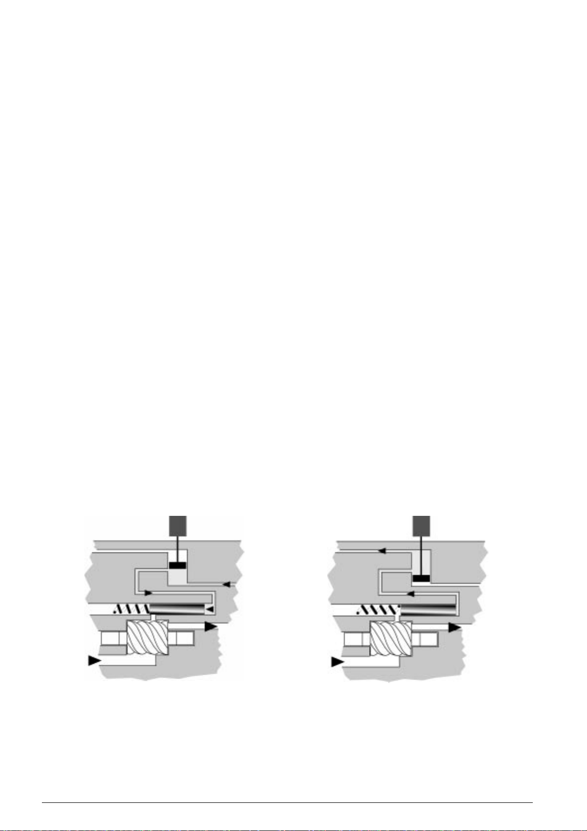
Durante il funzionamento a pieno carico del
compressore (vedi figura 2a), parte del
lubrificante ad alta pressione viene indirizzato
dalla valvola elettromagnetica a tre vie all’interno
del cilindro e, contrastando la pressione della
molla, spinge il pistone fino a chiudere la luce di
parzializzazione.
The capacity control device, by reducing the
standard refrigerating capacity of the
compressor , allows to make up for such situation
and to avoid efficiency troubles for the whole
cooling system.
All screw compressors are equipped with a
capacity control device at variable volume ratio,
having the following advantages:
• simple structure to assure accurancy of the
screw seats and the sturdiness of the screw
housing
• moving parts of the capacity control device
with no alignment problems.
The capacity control device consists of:
• a three-way solenoid valve directs the flow
of oil in high pressure during its functioning
• cylinder directly connected with the suction
side of the compressor
• piston that slides inside the cylinder
• contrast spring acting on a face of the piston
• capacity control hole reducing the
displacement and consequently reducing
the cooling capacity of the compressor.
This equipment is for each step of capacity
control, it results that for compressors with
two steps of capacity control (see table 10.1 at
page 22) double equipment is installed.
When compressor runs at full load (see fig. 2a)
part of the oil at high pressure, three-way
solenoid valve directs oil in high pressure inside
the cylinder opposing the spring thrust and
pushing the piston until it closes the capacity
control orifice.
During functioning at reduced load (see fig. 2b)
the solenoid valve directs the oil at high pressure
(trapped into the cylinder) into the suction side
of the compressor.
Die Leistungsregelung ermöglicht durch
Leistungsanpassungen, daß das Kältesystem
innerhalb der projektierten Parameter betrieben
wird.
Alle Schraubenverdichter sind mit einer
Leistungsregelung ausgestattet die nachfolgende
Vorteile bietet:
• einfacher Aufbau , gewährleistet die
Genauigkeit der Schraubensitze und die
Standfestigkeit des Gehäuses.
• alle beweglichen Teile der
Leistungsregelung haben keine
Ausrichtungsprobleme
Die Leistungsregelung besteht aus:
• Einem Drei-Wege-Magnetventil zur
Regelung des Hochdruckölflusses
• Zylinder, direkt verbunden mit der Saugseite
des Verdichters
• Kolben, der sich in dem Zylinder bewegt
• Gegenfeder auf einer Kolbenseite
• Leistungsregelungsbohrung reduziert das
Fördervolumen und damit
konsequenterweise die Kälteleistung des
Verdichters.
Diese Ausstattung ist gültig für jede Stufe der
Leistungsregelung , d.h. daß für eine zweistufige
Leistungsregelung eine doppelte Ausstattung
vorhanden ist (siehe Tabelle 10.1 auf Seite 22).
Beim Betrieb mit voller Leistung (siehe Abb . 2a)
leitet das Drei-Wege-Ventil Öl mit hohem Druck
in den Zylinder der Leistungsregelung und drückt
den Kolben entgegen der Feder bis die Öffnung
der Leistungsregelung geschlossen ist.
Während des Betriebes mit reduzierter Leistung
(siehe Abb. 2b) entläßt das Drei-Wege-Ventil das
in dem Zylinder der Regelung gefangene Öl (unter
Hochdruck) in die Saugseite des V erdichters.
FTEC11-01
2a 2b
funzionamento a pieno carico funzionamento a carico ridotto
full load operation capacity control operation
Vollastbetrieb Leistungsgeregelter Betrieb
controllo di capacità capacity control Leistungsregelung
fig. 2 fig. 2 Abb. 2
6
Page 7
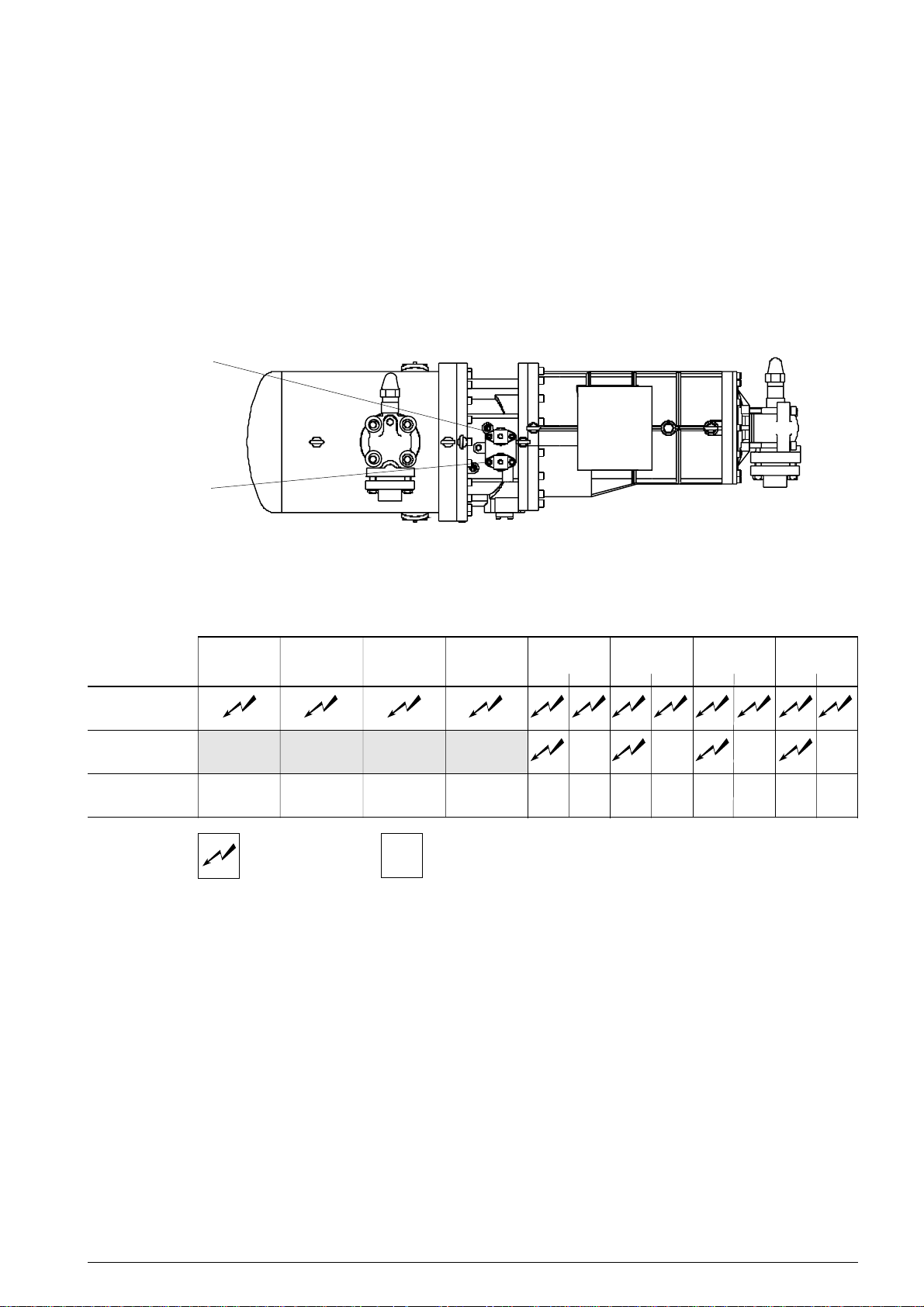
Durante il funzionamento a carico ridotto (vedi
figura 2b), la valvola elettromagnetica mette in
comunicazione l’olio ad alta pressione con il lato
di aspirazione del compressore.
Il lubrificante defluisce dal cilindro e la molla, in
distensione, sposta il pistone liberando così la
luce di parzializzazione.
In tali condizioni solo la rimanente porzione delle
viti (quella compresa tra la luce di parzializzazione
e la porta di scarico) opera la compressione del
refrigerante; a ridotta capacità volumetrica
corrisponde una ridotta capacità frigorifera.
Tale dotazione non può essere rimossa o
modificata.
V2
V1
The lubricant flows out of the cylinder and the
spring, which is no longer compressed,
moves the cylinder and make the capacity
control orifice free.
In such conditions only the remaining portion
of the screws (the one between the capacity
control orifice and the discharge door) carries
out the compression of the refrigerant; for a
reduced displacement and reducing the cooling
capacity .
Such device is standard equipment of any twin
screw compressor and can not be removed or
modified.
Das Öl fließt aus dem Zylinder und die Feder
bleibt nicht länger angespannt.
Sie schiebt den Kolben bis die Düsenöffnung
zur Leistungsregelung freigegeben ist.
In diesem Betriebszustand bringt nur noch der
verbleibende Rest der Schrauben (zwischen
Leistungs-regelungsöffnung und Hochdruckausgang) die Verdichtung des Kältemittels und
damit die reduzierte Kälterleistung (entsprechend
reduziertem Fördervolumen).
Diese Ausführung ist Standard für jeden DoppelSchraubenverdichter und kann nicht entfernt
oder modifiziert werden.
FTEC11-01
pieno carico
full load 100%
Vollast
posizione delle valvole elettromagnetiche solenoid valves location Anordnung der Magnetventile
fig. 3 fig. 3 Abb. 3
C-TSH8 30 120 Y C-TSH8 40 150 Y C-TSH8 50 186 Y C-TSH8 60 210 Y C-TSH8 70 240 Y C-TSH8 80 270 Y C-TSH8 90 300 Y C-TSH8 100 360 Y
C-TSH8 40 120 Y C-TSH8 50 150 Y C-TSH8 60 186 Y C-TSH8 70 210 Y C-TSH8 80 240 Y C-TSH8 90 270 Y C-TSH8 100 300 Y C-TSH8 120 360 Y
V1 V1 V1 V1 V1 V2 V1 V2 V1 V2 V1 V2
non disponibile non disponibile non disponibile non disponibile
75% not available not available not available not available
nicht verfügbar nicht verfügbar nicht verfügbar nicht verfügbar
50%
bobina alimentata
powered coil
Magnetspule unter Spannung
bobina non alimentata
coil not powered
Magnetspule stromlos
7
Page 8
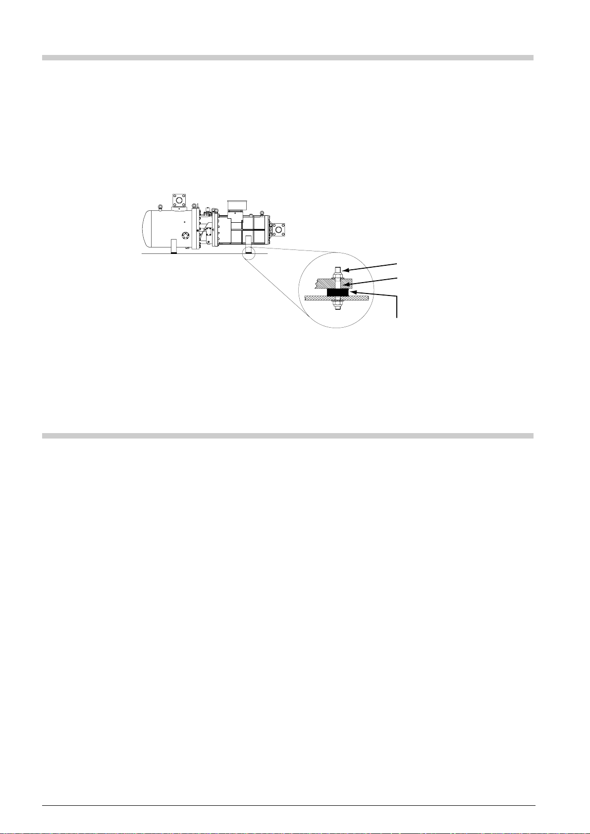
3. Fissaggio del compressore
3. Compressor fixing
3. Aufstellung des V erdichters
È essenziale che il compressore venga fissato in
posizione orizzontale al fine di evitare anomale
sollecitazioni e, soprattutto, garantire la corretta
lubrificazione.
Il compressore può essere fissato direttamente
al telaio, oppure interponendo i molleggi
antivibranti forniti con il compressore (vedi
figura 4) e applicando ai dadi la corretta coppia
di serraggio pari a 30Nm.
fig. 4 fig. 4 Abb. 4
It is essential that the compressor is fixed to a
frame perfectly horizontal that, besides to
guarantee a working without anomalous stresses,
is indispensable for the perfect lubrication of parts
in motion.
The compressor can be direct mounted rigidly
on the frame or with vibration absorbers supplied
with the compressor (see figure 4) applying the
correct tightening torque of 30 Nm.
Die Aufstellung des V erdichter muß waagerecht
erfolgen, um abweichende Beanspruchungen zu
vermeiden und die korrekte Schmierung zu
gewären.
Der Verdichter kann direkt am Rahmen
aufgestellt worden, oder mit
Schwingungsdämpfer geliefert mit den V erdichter
(siehe Abb.4) und indem an die Mutter die
richtige Drehmomente von 30 Nm befestigen.
M16
Ø 17 mm
Ø 50 mm
h = 20 mm
4. Lubrificazione
4.1 Il separatore integrato
Durante il funzionamento del compressore, il
flusso di refrigerante che fuoriesce dalla porta
di scarico trascina con sè una notevole quantità
di lubrificante che deve essere separato dal
refrigerante e convogliato nelle parti meccaniche
in movimento.
I compressori a vite serie C-TSH8 sono
equipaggiati con un separatore d’olio integrato
all’interno del quale l’olio si separa dal
refrigerante per gravità e attraversando il filtro
coalescente.
La figura 5 mostra una vista in sezione del
complesso separatore d’olio integrato/viti; nel
disegno si possono individuare gli elementi
essenziali del complesso che sono:
• condotto di compressione (riferimento 1).
Attraverso il condotto, il refrigerante (e il
lubrificante trascinato) viene convogliato
dalla porta di scarico del carter viti nel
separatore d’olio integrato; all’uscita del
condotto, la repentina diminuzione di velocità
e di direzione del flusso provoca una prima
separazione del lubrificante che si raccoglie
nella parte bassa del separatore.
• filtro coalescente (riferimento 2).
Il suo attraversamento da parte del
refrigerante, provoca una ulteriore
separazione del lubrificante.
4. Lubrication
4.1 Built-in oil separator
The screw compressor is characterised by a
lubrication system based on the injection of oil
into the parts in motion.
During functioning a huge quantity of lubricant
comes out from the screw compressor with a
pressure equal to the discharge one.
C-TSH8 series twin screw compressors are
equipped with a integral oil separator, where
inside lubricant is separated from the
refrigerant by gravity and impingement of the
oil demister.
Figure 5 shows the section view of the complete
oil separator/screws; from the drawing it is
possible to identify the basic elements of the
assemble, in details:
• discharge duct (reference 1).
Through the duct the refrigerant (and the
discharged lubricant) is directed from the
discharge port of the screw housing into the
integral oil separator.
At the outlet of the discharge duct the rapid
reduction in speed and flow direction
gives the first lubricant separation with the
separated oil falling into the lower part of
the separator.
• oil demister (reference 2).
The refrrigerant passing through the
demister gives an additional oil separation.
FTEC11-01
4. Schmierung
4.1 Angeflanschten Ölabscheider
Der Schraubenverdichter ist charakterisiert durch
ein Schmiersystem auf der Basis von
Öleinspritzung.
Während des Betriebes gelangt eine große
Menge Schmiermittel aus dem Verdichter mit
dem gleichen Druck der Hochdruckseite.
Während des Betriebes strömt eine große
Schmiermittelmenge aus dem Verdichter aus, die
von der Kältemittel getrennt werden soll und in den
mechanischen Teile in Bewegung befördert.
Die C-TSH8 Schraubenverdichter sind komplett
mit einem angeflanschten Ölabscheider und auf
der Innenseite trennt das Öl sich vom Kältemittel
für Schwere, Zentrifuge und Durchqueren von
Ölabscheiderfilter.
Die Abb.5 zeigt den Satz angeflanschten
Ölabscheider/Schrauben; in der Zeichnung
siehen sich die folgenden Hauptteilen:
• Druckleitung (Bezug 1).
Durch die Leitung, wird die Kältemittel (und
das geschleppte Schmiermittel) aus der
Drucktür der Schraubengehäuse in den
angeflanschten Ölabscheider befördert.
Bei Leitungsaustritt verursacht die
Verminderung der Fluß-geschwindigkeit und
-richtung eine erste Schmiermitteltrennung,
das in niedriges Seite des Ölabscheiders
sich sammelt.
8
Page 9
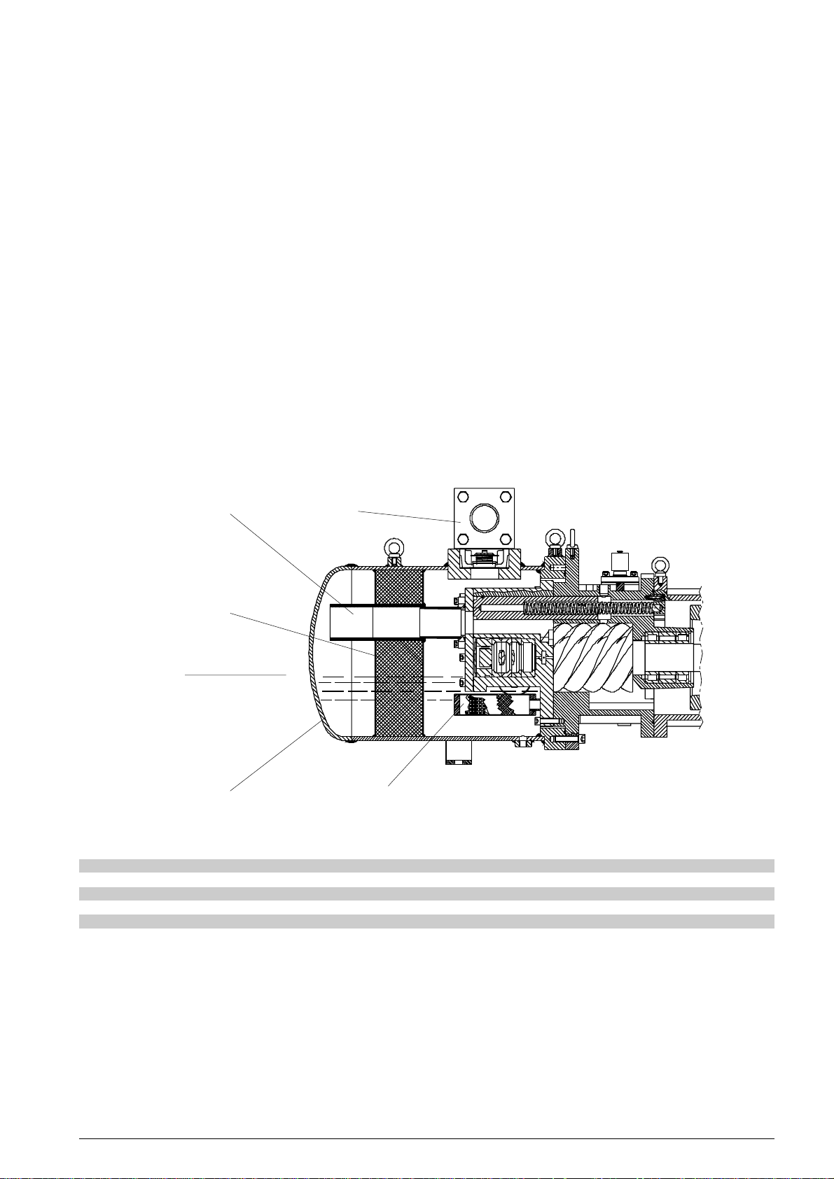
• mantello del separatore (riferimento 3).
La sua forma e dimensioni sono tali da
provocare sia una repentina diminuzione
della velocità che un brusco cambiamento
di direzione del flusso di refrigerante.
Al suo interno si raccoglie il lubrificante
separato, mentre il refrigerante viene
convogliato verso il rubinetto di
compressione (riferimento 4).
• filtro olio (riferimento 5).
È di tipo meccanico, con un grado di
filtrazione pari a 80 µm; è posizionato a
monte del condotto di lubrificazione così da
intercettare le particelle solide
eventualmente presenti nel lubrificante.
Dopo essere stato separato dal refrigerante e
filtrato attraverso il filtro meccanico, il lubrificante
spinto dall’alta pressione alla quale si trova, viene
iniettato tra le viti e nei cuscinetti.
L’olio oltre a provvedere alla lubrificazione delle
parti meccaniche in movimento, agisce da
sigillante dello spazio tra i profili delle viti.
• shell of the separator (reference 3).
Shape and dimensions give a rapid
reduction in speed and direction of the
refrigerant flow.
Inside the oil separator, separated lubricant
is collected in the sump while the refrigerant
is directed towards the discharge valve
(reference 4)
• oil strainer (reference 5).
It is a strainer with a grade of screening of
80 µm; oil demister is located before the
lubrication channel eliminating any foreign
parts getting back into the lubrication
system.
After the separation and filtration of the refrigerant
through the oil strainer, the lubricant is forced
by the discharge pressure and injected into the
screws and bearings.
Oil as well as providing lubrication between the
moving parts, the oil also acts as sealant between
the gap of the two screws.
• Ölabscheiderfilter (Bezug 2).
Bei Durchqueren des Ölabscheiderfilters von
der Kältemittel, verursacht man eine weitere
Schmiermitteltrennung.
• Außenmantel des Ölabscheiders (Bezug 3).
Die Form und Abmessungen verursachen eine
plötzliche Verminderung der
Kältemittelflußgeschwindigkeit und eine heftige
Änderung der Flußrichtung.
Auf der Innenseite sammelt sich das getrennte
Schmiermittel, während die Kältemittel sich auf
den Druckventil (Bezug 4) befördert.
• Ölfilter (Bezug 5).
Mechanischer Typ, mit Filterungsgrad von
80 µm.
Er liegt über die Schmierungsleitung, um die
eventuelle feste Teilchen in das
Schmiermittel abzufangen.
Nach Trennung von der Kältemittel und
Filtration durch mechanischer Filter, wird das
Schmiermittel zwischen Schrauben und in
den Lager eingespritzt, durch Schub von
Hochdruck. Das Öl schmiert die mechanische
T eilen in Bewegung und versiegelt den Raum
zwischen die Schraubenprofilen.
FTEC11-01
1
2
4
livello dell’olio
oil level
Ölstand
35
fig. 5 fig. 5 Abb. 5
1 condotto di compressione discharge duct Druckleitung
2 filtro coalescente oil demister Ölabscheiderfilter
3 mantello del separatore shell of the separator Außenmantel des Ölabscheiders
4 rubinetto di compressione discharge valve Druckventil
5 filtro olio oil strainer Ölfilter
4.2 Raffreddamento dell’olio
La temperatura di fine compressione gioca un
ruolo determinante nella durata e qualità del
lubrificante .
È in presenza di alte temperature che si creano
situazioni di rischio per la lubrificazione e quindi per
la integrità del compressore.
T ali alte temperature possono verificarsi durante
il funzionamento in condizioni gravose.
4.2 Oil cooling
The head temperature assumes an important
role in the working life and quality of the
lubricant because high temperatures cause
dangerous situations for lubrication and
consequently for the good working of
the compressor .
Such high temperature can be reached during
particularly hard working conditions.
9
4.2 Ölkühlung
Die hohe Temperatur spielt eine wichtige Rolle
für die Qualität und Lebensdauer des Öls.
Hohe Temperaturen führen für die Schmierung
zu gefährlichen Situationen und damit zu
schlechten Bedingungen für den Verdichter.
Die hohen Temperaturen können durch harte
Bedingungen erreicht werden.
In den Tabelle 10.13 “Anwendungsgrenzen”
Page 10
Nelle tabelle 10.13 “Campo di applicazione” è
segnalato in modo inequivocabile quando le
condizioni operative sono tali da richiedere il
raffreddamento dell’olio.
1000
In the tables 10.13 “Application limits”,
are unmistakably showed the working conditions
when oil cooling must be performed.
werden die Betriebsbedingungen
unmißverständlich dargelegt, bei denen das Öl
gekühlt werden muß.
100
80% olio - oil - Schmiermittel
10
viscosità cSt - viscosity cSt - Viskosität cSt
20 30 40 50 60 70 80 90 10O
temperatura dell’olio °C - oil temperature °C - Öltemperatur °C
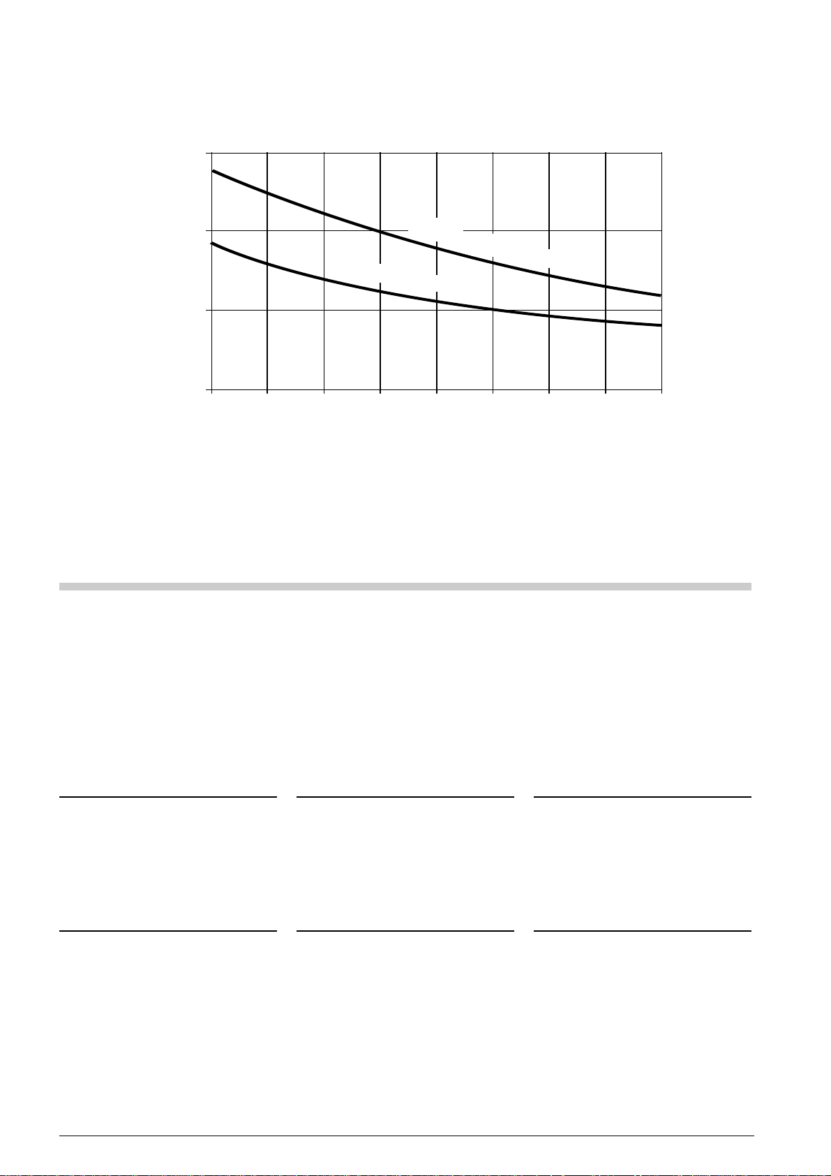
diagramma viscosità-temperatura viscosity-temperature diagram Viskosität-Temperaturschaubild
fig. 6 fig. 6 Abb. 6
5. Il lubrificante
L’olio iniettato tra le viti e nei cuscinetti, oltre a
provvedere alla loro lubrificazione, agisce da
sigillante tra i profili delle viti; ne risulta che è
molto importante che il lubrificante risponda a
precise caratteristiche di viscosità e solubilità.
È quindi essenziale che venga impiegato
esclusivamente lubrificante approvato da
FRASCOLD.
5. The lubricant
The oil injected to the screws not only lubricates
but also provide to seal the gap between the
screw profiles.
In order to ensure an excellent lubrication of the
compressor, are necessary suitable
characteristics of viscosity and solubility.
It is essential to use only lubricants approved by
FRASCOLD .
100% olio - oil - Schmiermittel
5. Schmiermittel
Das auf die Schrauben und die Lager
eingespritzte Schmiermittel dient nicht nur zur
Schmierung sondern dichtet die
Schraubenprofile ab.
Es ist sehr wichtig das, der Schmiermittel spezifische
Eigenschaften von Löslichkeit und Viskosität hat.
Bitte benutzen nur von FRASCOLD geprüfte
Schmiermittel.
FTEC11-01
5.1 Caratteristiche del lubrificante
Lubrificante FRASCOLD FCL
refrigerante R407C / R134a
viscosità cinematica:
a 40°C cSt 150
a 100°C cSt 14.5
punto di accensione °C 252
densità g/ml 0.96
Lubrificante FRASCOLD FCH
refrigerante R22
viscosità cinematica:
a 40°C cSt 150
a 100°C cSt 14.5
punto di accensione °C 252
densità g/ml 0.96
5.2 Raccomandazioni
• I limiti di impiego del compressore non
devono essere superati in nessuna
condizione operativa
5.1 Lubricant data
Lubricant FRASCOLD FCL
refrigerant R407C / R134a
kinematics viscosity:
at 40°C cSt 150
at 100°C cSt 14.5
flash point °C 252
density g/ml 0.96
Lubricant FRASCOLD FCH
refrigerant R22
kinematics viscosity:
at 40°C cSt 150
at 100°C cSt 14.5
flash point °C 252
density g/ml 0.96
5.2 Recommendations
• application limits are to be considered
values not to exceed in every working
conditions.
10
5.1 Schmiermitteleigenschaften
Schmiermittel FRASCOLD FCL
Kältemittel R407C / R134a
Kinematische Viskosität:
bei 40°C cSt 150
bei 100°C cSt 14.5
Flammpunkt °C 252
Dichtigkeit g/ml 0.96
Schmiermittel FRASCOLD FCH
Kältemittel R22
Kinematische Viskosität:
bei 40°C cSt 150
bei 100°C cSt 14.5
Flammpunkt °C 252
Dichtigkeit g/ml 0.96
5.2 Ausführungshinweise
• die Verdichter Anwendungsgrenzen
sollen unter keiner Bedingung
übergeschritten sein
Page 11
• l’evaporatore ad espansione diretta con
tubi corrugati deve rispondere a criteri
costruttivi particolari per impiego con
compressore a vite; consultare il fornitore
in merito
• Il lubrificante estere è altamente
igroscopico; per evitarne la
contaminazione adottare tutti gli
accorgimenti per impedire che durante
la sua manipolazione venga in contatto
con l’aria atmosferica.
5.3 Lubrificanti miscelati, sostituzione
del lubrificante
Non si devono miscelare lubrificanti con
caratteristiche differenti.
Tale evenienza si può verificare in occasione
di un reintegro della carica di lubrificante
oppure quando è necessario sostituire il
lubrificante acido o contaminato in impianti
funzionanti con refrigeranti HCFC/HFC.
Contattare l’Ufficio Tecnico FRASCOLD per
ulteriori suggerimenti.
• direct expansion evaporator with finned
tubes , has to meet special design criteria
when applied with screw compressor; get
in contact with evaporator supplier
• ester lubricant is highly hygroscopic;
to avoid lubricant contamination, performs
all the necessary procedures to prevent
the contact with atmosphere during oil
handling
5.3 Lubricant mixing,
oil replacement
It is not allowed the mixing of lubricants with
different characteristics.
This event takes place when it is necessary to
add oil or replace acid or contaminated lubricant
in systems with HCFC/HFC refrigerants.
For further details, please contact FRASCOLD
Technical Department.
• bei Direktexpansions- Verdampfern mit
berippten Rohhren kann eine Korrigierte
Auslegung erforderlich werden (bitte
kontaktieren der Lieferant)
• das Esteröl ist stark hygroskopisch
• es ist bei Troknung des Systems und im
Umgang mit geöffneten Ölgebinden
besondere Sorgfalt erforderlich.
5.3 Gemischte Schmiermittel,
Ölwechsel
Unterschiedliche Schmiermittel sollen nicht
gemischt werden.
Diese Gelegenheit kann eintreten beim
Wiedereinsetzung der Ölfüllung oder beim Ersatz
der säuere und verseuchte Öl im Anlagen mit
HCFC/HFC Kältemittel.
Für weitere Vorschläge steht die Technische
Abteilung von FRASCOLD zur Verfügung.
6. Installazione, tubazioni
frigorifere
Le procedure di installazione di un compressore
a vite sono simili a quelle da adottare per un
FTEC11-01
compressore alternativo.
Una maggiore capacità frigorifera può essere
ottenuta con l’installazione di un economizzatore
(vedi paragrafo 7.3 “Economizzatore”).
6.1 Tubazioni frigorifere
Ciascuna linea deve essere dimensionata e
realizzata in modo da favorire la circolazione del
refrigerante e il ritorno dell’olio con il
compressore in funzione ma ostacolare il ritorno
di refrigerante liquido con il compressore fermo.
6. Compressor installation,
piping
The installation of the screw compressor in the
refrigerant circuit requires similar procedures as for
a semi-hermetic reciprocating compressors.
Higher capacity can be achieved with the
installation of the economizer kit.
(See section 7.3 “Economizer”).
6.1 Piping
Each lines has to be dimensioned and realized
in order to favour the refrigerant circulation and
the oil return with the compressor operative, but
restrict the liquid refrigerant return during
stationary periods.
6. Verdichtersinstallation,
Rohrleitungen
Die Installation eines Schraubenverdichters
erfordert vergleichbare Maßnahmen mit der
Installation eines gleich großen
Hubkolbenverdichters und zusätzlich einen
Ölkreislauf.
Durch die Installation einer Economizer, ist eine
höhere Kälteleistung erreicht (siehe Abschnitte
7.3 “Economizer”).
6.1 Rohrleitungen
Die Leitungen müssen nach dem Stand der
Technik dimensioniert werden mit dem
Bestreben, den Kältemittelfluß und die Zirkulation
sowie eine einwandfreie Ölrückführung zu
gewähren.
3÷4 m
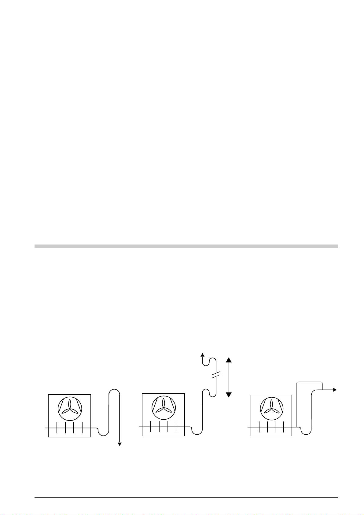
linea di uscita dell’evaporatore linea di uscita dell’evaporatore con montante e sifoni montante di circuito con controllo di capacità
evaporator outlet piping evaporator outlet piping and riser with traps suction line with capacity control
Rohritg. am Verdampferausgang Verdampferausgang mit Steigleitung und Falle Saugleitung bei Leistungsregelung
fig. 7 fig. 7 Abb. 9
11
Page 12
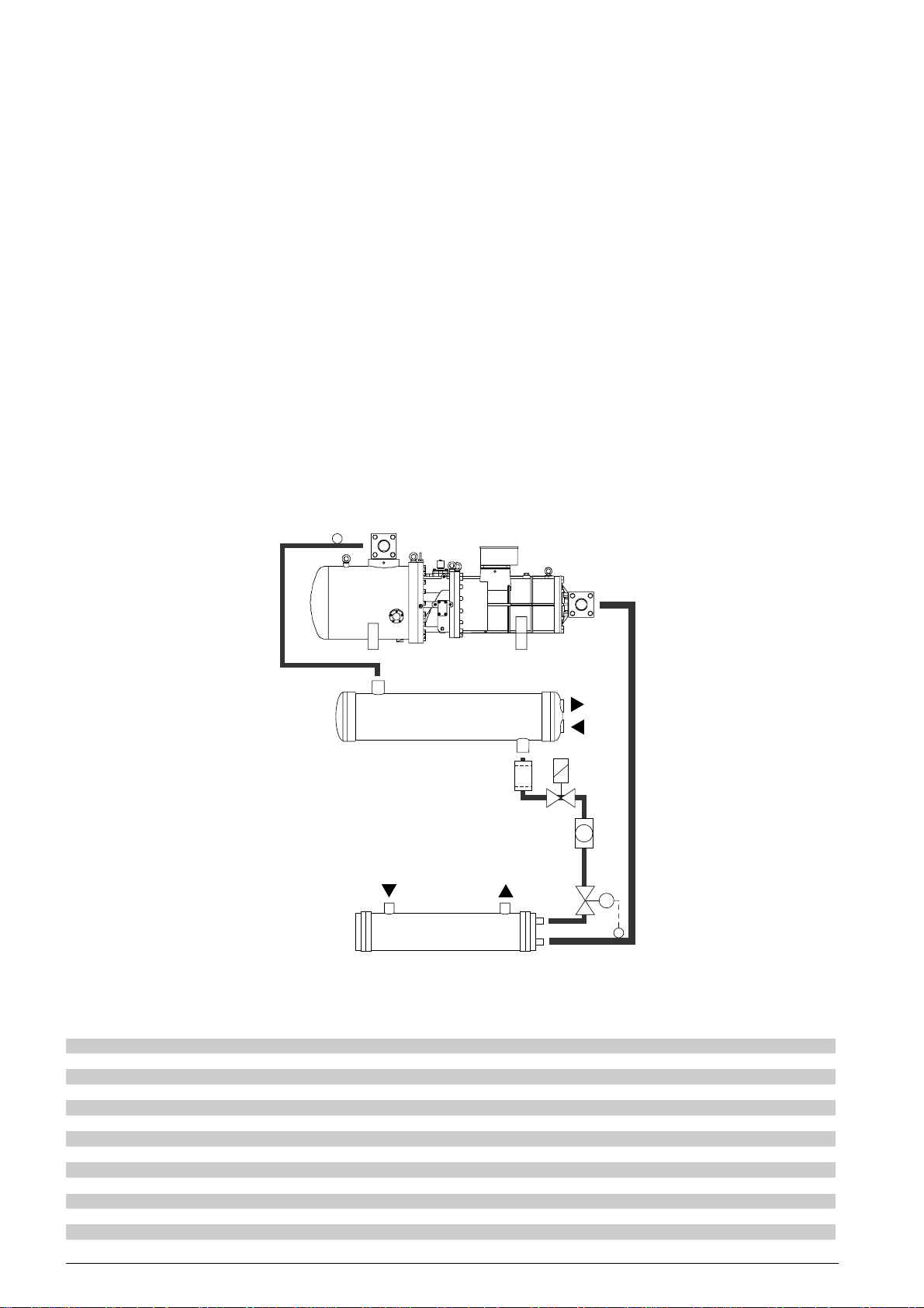
I principali criteri generali che stanno alla base
di una buona progettazione delle linee frigorifere
sono:
• per tutte le linee
- pendenza di almeno 1% nella direzione
del flusso
- velocità del refrigerante tale da garantire
il trascinamento del lubrificante senza
eccessive perdite di carico
• per le linee di aspirazione e compressione
- un sifone alla base di ogni colonna con
flusso ascendente
- un sifone ogni 3÷ 4 metri di colonna
con flusso ascendente
- all’uscita dell’evaporatore, un montante
(con sifone alla base) che, prima di
collegarsi al compressore, superi il
colmo dell’evaporatore stesso.
FRASCOLD suggerisce tale soluzione
anche per impianti con sistema “pumpdown”, così da evitare ritorni di liquido
The main general principles which are the basis
of a good refrigerating lines design are:
• for every line
- slope of at least 1% in the direction of
flow
- refrigerant velocity to allow the
refrigerant entrainment without
excessive pressure drop
• for suction and discharge lines
- one trap at the base of each column
with rising flow
- one trap each 3÷ 4 meters of column
with rising flow
- at the evaporator outlet one riser
(with trap at the base) that, before going
to the compressor, exceeds the
evaporator full.
FRASCOLD suggests to apply this
principle with “pump-down” system
also to avoid the liquid refrigerant to
flood the suction side of the compressor
Dabei ist zu verhindern, daß flüssiges Kältemittel
während der Stillstandsphase des Verdichters
zum Verdichter gelangt.
Die wichtigen Merkmale einer guten
Rohrleitungsauslegung sind:
• Für alle Leitungen
- Mindestens 1% Gefälle in Flußrichtung
- Ausreichend Kältemittelgeschwindigkeit
zur Vermeidung eines hohen
Druckabfalles
• Für Saug- und Druckleitungen
- Eine Falle am unteren Ende von
Steigleitungen
- Eine Falle nach 3-4 Metern bei höheren
Steigleitungen
- Am Verdampferausgang eine Falle mit
anschließender Steigleitung über die
Gesamthöhe des Verdampfers hinaus
- FRASCOLD empfiehlt im Übrigen die
„Pump-Down“ Schaltung des Systems
um eine Überflutung der
8
1
2
4
WO
WI
10
5
6
WI
WO
9
7
3
raffreddatore di liquidi liquid chiller Flüssigkeitskühlsatz
fig. 10 fig. 10 Abb. 10
1 compressore compressor Verdichter
2 condensatore condenser Verflüssiger
3 evaporatore evaporator Verdampfer
4 filtro deidratore filter drier Filtertrockner
5 valvola elettromagnetica solenoid valve Magnetventil
6 spia di passaggio sight glass Schauglas
7 valvola termostatica thermostatic expansion valve Expansionsventil
8 linea di compressione discharge line Druckleitung
9 linea del liquido liquid line Flüssigkeitsleitung
10 linea di aspirazione suction line Saugleitung
WI ingresso acqua water inlet Wassereintritt
WO uscita acqua water outlet wasseraustritt
FTEC11-01
12
Page 13

al compressore in caso di improvvisa
mancanza di alimentazione elettrica.
- negli impianti con controllo di capacità
particolarmente spinto, realizzare il doppio
montante per garantire il ritorno
dell’olio anche in condizioni di
carico ridotto.
Un’accorgimento supplementare consiste
nell’installare una valvola elettromagnetica prima
della valvola termostatica per evitare trafilamenti
di refrigerante liquido durante le fasi di arresto.
Immediatamente dopo il rubinetto di mandata
del compressore, è necessario che la tubazione
abbia un andamento discendente.
Le linee frigorifere vicine al compressore devono
essere sufficientemente flessibili e avere, il più
possibile, un andamento parallelo all’asse di
rotazione.
In funzione del tipo di refrigerante e delle
condizioni di impiego, evitare linee di aspirazione
eccessivamente lunghe.
In caso di circuito realizzato sul luogo di
installazione, impiegare un filtro di aspirazione
(grado di filtrazione 25 µm) per proteggere il
compressore dai danni causati dalla presenza
di eventuali residui solidi nel sistema frigorifero.
Per evitare eccessive concentrazioni di
refrigerante nel lubrificante durante le fasi di
arresto del compressore, installare il riscaldatore
olio a fascia da 300W fornito con il compressore
stesso (vedi 10.2 “Dotazione standard”).
Con il compressore installato in un ambiente
molto freddo oppure funzionante con elevate
FTEC11-01
temperature di compressione, è necessario
rivestire il separatore integrato con materiale
termoisolante.
in case or power cuts.
- in case of cooling system with
large capacity control it is necessary
to realize a twin riser to grant the oil
return with reduced capacity .
Additional safety is provided by a solenoid
valve fitted directly before the thermostatic
expansion valve to prevent liquid bleeding during
standstill periods.
In addition, the discharge line should first be run
with a fall after the shut-off valve.
Nevertheless, the piping of the cooling system
has to be flexible and not exert any strain
on the compressor.
Pipes running parallel to the compressor axis
have been found to be favourable.
Critical length of pipe sections should be avoided
(dependent upon operating conditions and
refrigerant).
The installation of a suction side clean-up filter
(screening 25 µm) will protect the compressor
from damage due to debris from the system
and is strongly recommended for individually
built plants.
The 300 W oil heater, supplied with the
compressor (see 10.2 “Standard equipment”),
must fasten the oil separator shell to prevent
high concentration of refrigerant in to the
lubricant during the standstill of the compressor .
If the compressor is located in low temperature
ambient or in case of operation with high
discharge pressure, the built-in oil separator must
be insulated.
Verdichtersaugseite zu vermeiden
- In den Anlagen mit Hohen
Leistungsreduzierungen, durch führen
den Doppelstiel um die doppelte
Ölrückkehr zu gewähren, auch unter
Bedingungen von Reduktionsfüllung.
Zusätzliche Sicherheit ist zu gewinnen durch
den Einbau eines Magnetventils unmittelbar
vor dem E-Ventil um ein Vollaufen des
Verdampfers während der Stillstandsphase zu
verhindern.
Die Druckleitung sollte nach dem V erdichter ein
Gefälle aufweisen.
Die Rohrleitungen müssen derart installiert sein,
daß keine Spannungen für den Verdichter
entstehen. Dabei sind Leitungen, die parallel zur
Verdichterachse verlegt sind, zu bevorzugen.
Übermäßig lange Rohrleitungen sollten
vermieden werden (hängt von der Anwendung
und vom Kältemittel ab).
Die Installation eines Saugleitungsfilters
(mit 25 µm) wird den Verdichter vor
Beschädigung durch verbliebene Schmutzteile
schützen und ist dringend zu empfehlen, vor
allem bei individuell gebauten Anlagen.
Um hohe Kältemittelanreicherung im Schmieröl
während der Verdichterstillstandsperioden zu
verhindern, dient eine Ölheizung von 300 W,
die mit dem Verdichter geliefert ist (siehe 10.2
“Standard Ausrüstung”).
Betrieb bei niedrigen Umgebungstemperaturen
oder mit hohen Temperaturen auf der
Hochdruckseite während dem Stillstand erfordert
zusätzliche Isolierung des Ölabscheiders.
7. Condizioni di impiego
particolari
Se installato in ambiente molto freddo, è
necessario isolare termicamente il separatore
per evitare che al suo interno il refrigerante
condensi durante le fasi di arresto del
compressore.
Nel caso in cui il compressore o la linea di
aspirazione siano posti in ambienti con
temperatura inferiore a quella dell’evaporatore,
è necessario realizzare il funzionamento “pumpdown”.
In questo caso, per evitare danni derivanti dalla
migrazione di liquido, il pressostato di bassa
pressione deve essere tarato ad un valore
inferiore alla minima pressione di aspirazione di
lavoro del compressore.
7. Special operative
conditions
When oil separator is placed in a cold site, it
must be properly insulated to avoid the
refrigerant condensing inside during
standstill periods.
If the compressor or suction line reach
temperature lower then the one of the evaporator ,
a “pump-down” circuit must be realized.
The cut-in point of the low pressure switch must
lower than the lowest suction pressure od the
compressor.
It is recommended to perform any sort of
procedure to grant minimum difference in
pressure of 4 bar between discharge and suction
within 10 seconds from compressor starting.
For flooded evaporator, fit the system with a
13
7. Besondere
Systembedingungen
Im Falle niedriger Umgebungstemperaturen,
ist eine Isolierung des Ölabscheiders
erforderlich, um innen die
Schmiermittelkondensation beim Verdichterstop
zu vermeiden.
Wenn der Verdichter oder die Saugleitung
Temperaturen ausgesetzt werden, die tiefer als
die T emperatur des V erdampfers sind, muß eine
„Pump-Down“ Schaltung realisiert werden.
Um Schaden von Flüssigkeitsverlagerung zu
vermeiden, soll der Startbefehl des NiederdruckPressostat unterhalb der niedrigst
vorkommenden Druck erfolgen.
Es sollten alle Maßnahmen vorgenommen
werden um einen Mindestöldruck von 4 bar,
Page 14

Si suggerisce di adottare tutti gli accorgimenti
necessari per garantire che, entro 10 secondi
dall’avviamento del compressore, venga
raggiunta una differenza di pressione di almeno
4 bar tra compressione e aspirazion).
In impianti con evaporatore allagato, è necessario
installare una valvola elettromagnetica abbinata
a una valvola regolatrice della pressione del
carter; deve essere installata a un livello
superiore a quello di uscita della linea di
aspirazione e deve chiudersi all’arresto del
compressore.
In impianti con temperature di evaporazione alte
e condensatore remoto a installazione esterna,
si può verificare la migrazione di refrigerante in
occasione di basse temperature ambiente.
Anche negli impianti con condensatore e/o
evaporatore multi-circuito, si può manifestare la
migrazione di refrigerante verso l’evaporatore.
Adottare appropriate soluzioni, da valutare caso
per caso, per evitare tale situazione.
Impianti dotati di sbrinamento con gas caldo
oppure con valvola di inversione del ciclo
frigorifero, richiedono soluzioni da valutare caso
per caso per proteggere il compressore dai danni
causati da ritorni di liquido e aumentata
migrazione di olio.
L ’installazione di un accumulatore di aspirazione
eviterà ritorni di liquido al compressore.
Durante l’inversione del ciclo frigorifero, una
temperatura dell’olio maggiore di 30÷40K di
quella di condensazione eviterà la migrazione di
lubrificante causata dalla rapida diminuzione di
pressione all’interno del separatore.
Per impedire riduzioni di pressione nella linea di
compressione, si raccomanda di installare una
valvola regolatrice della pressione di
condensazione sulla linea di compressione.
In particolari condizioni operative, è possibile
arrestare per un breve periodo il compressore
prima dell’inversione del ciclo frigorifero, quindi
riavviarlo non appena le pressioni in aspirazione
e compressione sono equalizzate.
In tale caso, è necessario verificare che entro
10 secondi dall’avviamento, si stabilisca la
minima differenza di pressione (4 bar) tra
compressione e aspirazione.
7.1 Iniezione di liquido
La valvola di iniezione di liquido deve essere
dotata di speciale carica termostatica adatta ad
operare con le alte temperature di scarico del
compressore.
Il bulbo della valvola di iniezione deve essere
messo in contatto con il tubo di compressione del
compressore, alla distanza di 10÷15 cm d al
rubinetto di compressione.
La zona di tubo a contatto con il bulbo deve
essere ben pulita quindi ricoperta di pasta
conduttrice; una volta posizionato , il bulbo deve
essere strettamente fissato alla tubazione, il tutto
deve essere ricoperto di materiale
termo-isolante.
solenoid valve combined with a crankcase
pressure regulating valve; it must be installed in
a point higher than the suction outlet and is
closed during compressor standstill.
Cooling systems with low evaporating
temperature and outdoor condenser installation,
refrigerant migration can occours when the
ambient temperature is very low.
Refrigerant migration to the evaporator can occours
in multi-circuit condenser and /or evaporator;
perform suitable procedures to avoid it.
Systems with reversing cycle valve or hot gas
defrost, individual solution must be applied
to protect the compressor against liquid
slugging and increased oil migration.
The installation of a suction accumulator is
recommended to protect the compressor against
damages caused by liquid slugging.
During reversing cycle mode, the fast pressure
reduction in to the lubricant separator causes
the oil migration; keep the oil temperature
30÷40K higher than condensing temperature
to avoid lubricant migration.
To prevent low pressure in the discharge line,
the installation of a discharge pressure regulating
valve is strongly recommended; the valve has
to be installed on the discharge line.
Under certain operative conditions it is possible
to stop the compressor for a short period before
the reversing cycle mode; as soon as the suction
and discharge pressures have been equalized,
the compressor can be started again.
With this procedure, verify that the minimum
pressure difference (4 bar) between suction and
discharge takes place no later than 10 second
after the compressor starting.
7.1 Liquid injection
The liquid injection valve has to be equipped
with thermostatic charge specific to operate with
discharge temperature.
The contact area of the bulb of the liquid injection
valve bulb is on the compressor discharge line,far
10÷15 cm from the discharge valve.
Brush the contact area of the bulb, then apply
heat transfer paste, place the bulb and fasten it
to the pipe; wrap all with thermal insulator.
Draw line for liquid refrigerant comes from the
horizontal section of main liquid line, then it
directs downward.
Complete the liquid injection line with filter drier ,
sight-glass, and solenoid valve to shut-off the
flow when compressor stops.
Contact FRASCOLD Technical Department or
use our software of screw compressors
performance calculation for the correct matching
between model of compressor and model of
liquid injection kit selected by FRASCOLD.
7.2 Unloading start
The starting of a screw compressor requires a
very low starting torque because the following
reasons:
innerhalb 10 Sekunden nach dem Verdichterstart
zu erreichen.
Bei Anlagen mit überfluteten Verdampfern, ist
ein Magnetventil kombiniert mit einem
Gehäusedruckreglerventil, erforderlich.
Es soll direkt oben am Saugleitungsaustritt
eingebaut werden und es schließt sich bei
Verdichterstillstand.
Bei Anlagen mit hohen
Verdampfungstemperaturen und
Verflüssigeraufstellung im Freien, kann die
Kältemittelverlagerung bei niedrigen
Außentemperaturen sich ereignen.
Auch bei Anlagen mit Mehrkreis-verflüssigern
und/oder -verdampfern besteht die Gefahr von
Kältemittelverlagerung in den Verdampfer.
Um diese Situation zu vermeiden, bitte wenden
geeigneten Lösungen an, die anfallweise
eingeschätzt werden sollen.
Anlagen mit Heißgasabtauung oder mit
Kreislaufumkerungsventil erfordern anfallweise
schätzbare Lösungen, um den Verdichter vom
Schaden für Flüssigkeitsschläge und erhöhte
Ölverlagerung zu schutzen.
Die Installation einem Saugakkumulator wird
Flüssigkeitsschläge vermeiden.
Während die Kreislaufumkehrung, soll die
Öltemperatur höher von 30 ÷ 40K als der
Verflüssigungstemperatur liegen, um die
Schmiermittelverlagerung zu vermeiden.
Ein Druckregler über den Druckleitung wird
empfohlen, um Druckabsenkungen zu verhindern.
Unter besonderen Betriebsbedingungen, ist es
möglich den Verdichter vor der
Kreislaufumkehrung kurz anzuhalten und nach
Druckausgleich wieder zu starten.
In diesem Fall, ist es erforderlich zu prüfen, daß
innerhalb 10 Sekunden nach dem
Verdichterstart, der Mindestdruckdifferenz (4 bar)
sich festsetzt.
7.1 Flüssigkeitseinspritzung
Die Flüssigkeitseinspritzventil soll mit spezielle
thermostatische Füllung komplett sein, geeignet
für die hohe Verdichtersdrucktemperaturen.
Der Ventilfühler soll an der Druckgasleitung,
10 ÷ 15 cm vom Druckabsperrventil entfer nt.
Diese Zone soll sortfältig sauber und mit
Wärmeleitpaste benetzten sein.
Der Fühler ist mit Rohrschellen zu befestigen
und zu isolieren.
Die Abziehungsleitung soll mit einem
horizontalen Hauptleitunsabschnitt verbunden
sein aus zunächst nach unten geführt werden
Die Flüssigkeitseinspritzleitung soll komplett mit
T rocknerfilter, Schauglas und Magnetventil um der
Fluß bei den Verdichterhaltung auszuschalten.
Fragen Sie an unsere Technische Abteilung
oder benutzen die software der
Schraubenverdichtersleistungs für die Korrekte
Zuordnung von Verdichter und
Flüssigkeitsspritzung Satz von FRASCOLD
gewählt.
FTEC11-01
14
Page 15
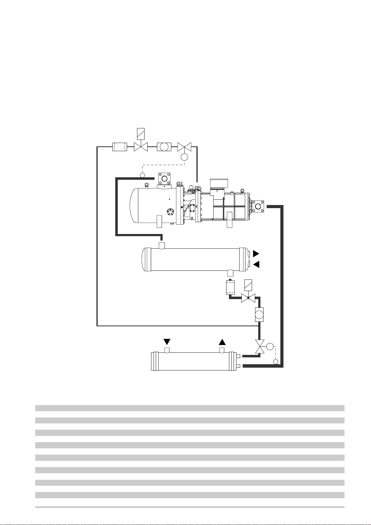
Il tubo di spillamento del refrigerante liquido,
deve essere collegato a un tratto orizzontale
della linea principale del liquido e quindi
assumere un andamento verticale con flusso
verso il basso
La linea di iniezione liquido deve essere
equipaggiata con filtro deidratore, indicatore
di passaggio e valvola elettromagnetica per
intercettare il flusso all’arresto del compressore.
Contattare il nostro Ufficio Tecnico oppure
utilizzare il software delle prestazioni dei
compressori a vite per il corretto abbinamento
• when compressor starts; the inertia for the
parts with rotatory motion (the screws)
is lower than that of a traditional
reciprocating compressor
• when compressor stops; the refrigerant
trapped in the discharge area, flows
back to the low pressure side of the
compressor causing a brief counter -rotation
of the screws.
A pressure equalization takes place between
suction and discharge.
7.2 Anlaufentlastung
Beim Startvorgang benötigt man ein sehr
niedriges Drehmoment aus folgenden Gründen:
• Wenn der Verdichter anläuft ist das
Trägheitsmoment der drehenden Teile
wesentlich niedriger als der Hub beim
traditionellen Hubkolbenverdichter
• Wenn der Verdichter anhält, strömt
Kältemittel zurück in den Hochdruckbereich,
gelangt zurück in den Niederdruckbereich
des Verdichters und führt so zu einer kurzen
FTEC11-01
12
4
5
11
6
1
8
WO
2
WI
4
5
10
6
WI
WO
9
7
3
iniezione di liquido liquid injection Flüssigkeitsspritzung
fig. 11 fig. 11 Abb. 11
1 compressore compressor Verdichter
2 condensatore condenser Verflüssiger
3 evaporatore evaporator Verdampfer
4 filtro deidratore filter drier Filtertrockner
5 valvola elettromagnetica solenoid valve Magnetventil
6 spia di passaggio sight glass Schauglas
7 valvola termostatica thermostatic expansion valve Expansionsventil
8 linea di compressione discharge line Druckleitung
9 linea del liquido liquid line Flüssigkeitsleitung
10 linea di aspirazione suction line Saugleitung
11 valvola iniezione liquido liquid injection valve Flüssigkeitseinspritzventil
12 linea iniezione liquido liquid injection line Flüssigkeitseinspritzleitung
WI ingresso acqua water inlet Wassereintritt
WO uscita acqua water outlet wasseraustritt
15
Page 16

tra modello del compressore e kit di iniezione
liquido selezionato da FRASCOLD.
7.2 Avviamento in vuoto
Il particolare progetto del compressore a vite
richiede basse coppie di spunto perchè:
• all’avviamento, l’inerzia di parti con moto
rotatorio (le viti) è decisamente inferiore a
quella di parti con moto alternativo (tipico
dei compressori tradizionali)
• al momento dell’arresto, il refrigerante
presente nella zona di compressione rifluisce
verso la zona di bassa pressione del
compressore provocando una breve
controrotazione delle viti; così facendo, le
pressioni in aspirazione e mandata si
equalizzano favorendo il successivo
avviamento del compressore
• al momento dell’avviamento, il compressore
è parzializzato al 50% e la conseguente
riduzione del volume spostato ritarda lo
stabilirsi della differenza di pressione tra
aspirazione e mandata.
Grazie alle caratteristiche sopra citate, il
compressore a vite non richiede l’impiego del
dispositivo di avviamento a vuoto.
7.3 Economizzatore
Un sensibile miglioramento dell’efficienza del
compressore lo si ottiene sottoraffreddando
ulteriormente il refrigerante liquido
(aumentandone così il suo contenuto entalpico)
prima del suo ingresso nella valvola termostatica.
Per operare tale sottoraffreddamento, è
necessario impiegare un economizzatore (vedi
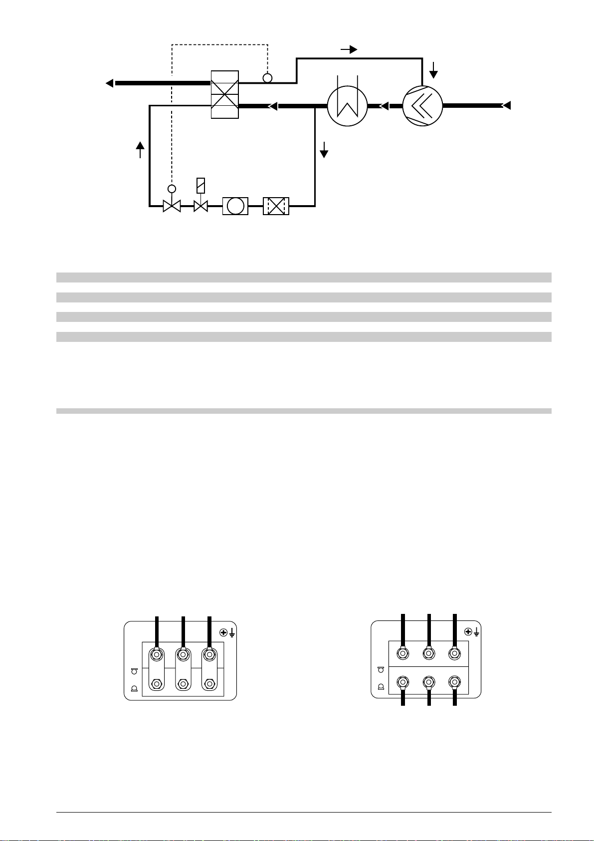
figura 12) essenzialmente composto da uno
scambiatore a piastre (riferimento 1) e da una
valvola termostatica (riferimento 2) che installata
sulla linea di alimentazione dello scambiatore
controlla il surriscaldamento del refrigerante
reintrodotto nel compressore.
Oltre alla valvola termostatica, il circuito di
alimentazione dell’economizzatore deve
prevedere anche una valvola elettromagnetica
(riferimento 3) e un indicatore di passaggio
(riferimento 4); è consigliabile completare il
circuito con un filtro deidratore (riferimento 5).
Le tabelle riportate a partire da pagina 31,
riportano i valori di prestazione dei compressori
dotati di economizzatore.
Contattare il nostro Ufficio Tecnico oppure
utilizzare il software delle prestazioni dei
compressori a vite per il corretto abbinamento
tra modello del compressore e kit
economizzatore selezionato da FRASCOLD.
• when compressor starts, the capacity control
device is set on 50%, in such a way the
reduced swept volume delays the
establishment of the difference between
suction and discharge.
The above allows screw compressor not to
require an unloading start device.
7.3 Economizer
It is possible to increase the compressor
efficiency by means an additional sucooling of
liquid refrigerant (in this way the refrigerant
enthalpy is increased) just before ist injection
into thermostatic expansion valve.
To perform this additional subcooling, it is
necessary to use an economizer (see figure 12);
essentially , it consists in an plate heat exchanger
(reference 1), a thermostatic expansion valve
(reference 2) installed on the inlet line
of the exchanger and controlling the
superheating of the refrigerant introduced
into the compressor.
Besides the thermostatic expansion valve, the
piping of the economizer has to be equipped
with the solenoid valve (reference 3) and the
sight glass (reference 4).
Economizer piping has to be completed with a
filter drier (reference 5).
Data tables from page 31, show the
performances of the compressors when
equipped with economizer.
Contact FRASCOLD Technical Department or
use our software of screw compressors
performance calculation for the correct matching
between model of compressor and model of
economizer selected by FRASCOLD.
Rückwärtsdrehung der Schrauben , die
wiederum einen Druckausgleich zwischen
Hochdruck- und Niederdruckseite bewirkt
• Wenn der Verdichter startet befindet sich die
Leistungsregelungseinrichtung auf der Stufe 50%,
so daß durch die Erhöhung der Druckdifferenz
zwischen Hoch- und Niederdruck eine
Reduzierung des Fördervolumens passiert.
Durch die vorgenannten Funktionen benötigen
Schraubenverdichter keine besondere
Anlaufentlastung.
7.3 Economizer
Es ist möglich die Verdichterwirtschaftlichkeit
noch zu verbessern durch eine zusätzliche
Kältemittelunterkühlung unmittelbar vor dem
Eintritt in das Expansionsventil.
Um diese zusätzliche Unterkühlung zu realisieren
braucht man einen Economizer (siehe Abb .12),
der grundsätzlich aus einem
Plattenwärmeaustauscher (Pos. 1) , einem
thermostatischen Expansionsventil (Pos. 2) , das
auf der Eintrittsseite des Wärmetauschers
installiert ist und die Überhitzung des Kältemittels
beim Eintritt in den Verdichter kontrolliert.
Zusätzlich zum E-Ventil muß die V errohrung mit
einem Magnetventil (Pos.3) Schauglas (Pos. 4)
und Filtertrockner (Pos.5) ausgeführt werden.
Die Leistungsangaben bei Economizerbetrieb
sind auf Seite 31 dargestellt.
Fragen Sie an unsere Technische Abteilung
oder benutzen die software der
Schraubenverdichtersleistungs für die Korrekte
Zuordnung von Verdichter und Economizer von
FRASCOLD gewählt.
FTEC11-01
16
Page 17
U (1)
V (2)
W (3)
Z (7)
X (8)
Y (9)
L1
L2
L3
L1
L2
L3
1
76
2453
economizzatore economizer Economizer
fig. 12 fig. 12 Abb. 12
1scambiatore a piastre plate heat exchanger Plattenwärmetauscher
2 valvola termostatica thermostatic expansion valve Thermostatische Expansionsventil
3 valvola elettromagnetica solenoid valve Magnetventil
4 indicatore di passaggio sight glass Schauglas
5 filtro deidratore filter drier Trockner
6 compressore compressor Verdichter
7 condensatore condenser Verflüssiger
8. Motore elettrico
I compressori sono azionati da un motore
FTEC11-01
elettrico asincrono trifase bipolare, con
avvolgimento frazionato (Part-Winding).
Modificando il collegamento elettrico del motore
(vedi figura 13), si ottengono due diversi tipi di
avviamento del compressore:
• avviamento diretto (D.O.L. Direct On Line)
• avviamento frazionato (P.W.S. Part Winding
Start).
L’avviamento frazionato del compressore (con
ripartizione della corrente 50% + 50%)
comporta una sensibile riduzione della corrente
di spunto.
Le caratteristiche elettriche dei motori disponibili
sono illustrate a pagina 22, tavola 10.1.
W (3)
Y (9)
8. Electric motor
Compressors are driven by a two-pole threephase, asynchronous electric motor with Part
Winding Start.
Performing different wirings (see figure 13), it is
possible to get two different starting modes:
• direct on line starting (D.O.L.)
• part winding start (P.W.S.)
Part winding start of the compressor (with
50% + 50% current distribution) results in a
remarkable reduction of locked rotor current.
Electric features of the available motors are listed
on page 22, table 10.1.
8. Elektromotor
Die Verdichter werden von 2-poligen,
dreiphasigen asynchronen Elektromotoren mit
Teilwicklungsstart angetrieben.
Bei Änderung die elektrische Motorverbindung
(siehe Abb.13), erhaltet sich zwei verschiedene
Verdichtersanlauftypen:
• Direktanlauf (D.O.L.)
• Teilwicklungsanlauf (P.W.S.)
Der Teilwicklungsanlauf der Verdichter (mit
Stromverteilung 50% + 50%) bestimmt eine
sinnliche Senkung der Anlaufstrom.
Die verfügbaren Versionen der Elektromotoren
sin auf Seite 22, Tabelle 10.1 aufgelistet.
L2
V (2)
X (8)
L1
U (1)
Z (7)
L3
collegamento per avviamento diretto (D.O.L.)
wiring for direct on line start (D.O.L.)
Anschluß für Direktanlauf (D.O.L.)
collegamento per avviamento frazionato (P.W.S.)
wiring for part winding start (P.W.S.)
Anschluß für Teilwicklungsanlauf (P.W.S.)
morsettiera del compressore compressor terminal board Verdichtersklemmkasten
fig. 13 fig. 13 Abb. 13
17
Page 18

9. La protezione
9. Compressor protection
9. Verdichterschutz
Per garantire una elevata affidabilità di
funzionamento, condizione indispensabile per
compressori di tale potenza, tutti i modelli
C-TSH8 sono equipaggiati con un dispositivo di
protezione, completo di modulo elettronico
KRIWAN INT390R e sensori a termistore (vedi
schema 10.16, pagina 44), che svolge le
seguenti funzioni:
• controllo della massima temperatura
del motore elettrico (+120°C) mediante
sei termistori di tipo PTC inseriti
nell’avvolgimento dello statore.
Funzione con riarmo manuale (pulsante MR).
• controllo della massima temperatura
di compressione (+120°C) tramite un
sensore di tipo PTC posto sullo scarico
del compressore.
Funzione con riarmo manuale (pulsante MR).
• controllo del senso di rotazione del motore
elettrico e della successione delle fasi.
Funzione con riarmo manuale (pulsante MR).
• protezione contro mancanza di fasi e cadute
di tensione.
In caso di intervento per mancanza di fase
oppure asimmetria tra le fasi il riavviamento
del compressore avviene automaticamente
dopo una pausa di 30 minuti.
• controllo di interruzioni o corto circuito nei
circuiti dei sensori PTC.
Funzione con riarmo manuale (pulsante MR).
In order to ensure highly reliable functioning,
which is fundamental for compressors of such
power, all C-TSH8 models are equipped with
a suitable electronic protection device
KRIWAN INT390R and thermistor sensors (see
scheme 10.16, page 44), with the following
functions:
• control of the maximum temperature
of the electric motor (+120°C) through
six PTC thermistors included in the
stator winding.
Switch MR for manual reset.
• control of the maximum discharge
temperature (+120°C) through a PTC
sensor placed on the compressor
discharge side.
Switch MR for manual reset.
• control of the rotation direction of the
electric motor and phase sequence.
Switch MR for manual reset.
• protection against phase and voltage
failures.
Compressor stops due to phase failures;
compressor automatically starts after 30
minutes.
• control of breakage and short circuit in chain
of PTC sensors.
Switch MR for manual reset.
Um eine sichere Funktion zu gewährleisten,
die eine fundamentale Eigenschaft eines
solch großen Verdichters sein muß, sind
alle Modelle mit entsprechenden elektronischen
Schutzeinrichtungen KRIWAN INT390R
und Thermistorfühler (siehe Schema 10.16,
Seite 44) versehen.
Die Funktionen sind:
• Überwachung der maximalen
Wicklungstemperatur (+120°C) durch
sechs PTC Thermistoren, die in den
Statorswicklung eingeschaltet sind.
Drücken MR für die Handwiedereinsetzung.
• Überwachung der maximalen
Druckgastemperatur (+120°C) durch einen
PTC Fühler auf den Verdichtersablaß.
Drücken MR für die Handwiedereinsetzung.
• Überwachung der Drehrichtung des
Elektromotors.
Drücken MR für die Handwiedereinsetzung.
• Schutz gegen Phasen - und
Spannungsausfall.
Der Verdichter haltet sich wegen
Phasenmangel oder Phasenasymmetrie
an; er läuft wieder automatisch nach 30
Minuten an.
• Überwachung der Leiterbruch oder
- kurzschluß im PTC - Meßkreis.
Drücken MR für die Handwiedereinsetzung.
FTEC11-01
18
Page 19

10. Tavole, disegni,
dati tecnici
10. Data tables, drawings,
diagrams
10. Daten, T abellen,
Zeichnungen, Diagramme
10.1 Dati tecnici
10.2 Dotazione standard
10.3 Riscaldatore olio
10.4 Accessori
10.5 Raffreddatore d’olio ad acqua
10.6 Raffreddatore d’olio ad aria
10.7 Filtro olio
10.8 Flussostato
10.9 Modulo elettronico per flussostato
10.10 Valvola elettromagnetica
10.11 Indicatore di passaggio olio
10.12 Temperature intermedie di saturazione
10.13 Campo di applicazione
10.14 Simboli
10.15 Dati di prestazione
10.16 Schemi elettrici
10.17 Legenda
10.18 Dimensioni di ingombro
10.1 Technical data
10.2 Standard equipment
10.3 Oil heater
10.4 Accessories
10.5 Water cooled oil cooler
10.6 Air cooled oil cooler
10.7 Oil strainer
10.8 Flow switch
10.9 Electronic module for flow switch
10.10 Solenoid valve
10.11 Oil sight glass
10.12 Intermediate saturation temperature
10.13 Application limit
10.14 Symbols
10.15 Performance data
10.16 Wiring diagrams
10.17 Legend
10.18 Dimensional drawings
10.1 Technische Daten
10.2 Standard Ausrüstung
10.3 Ölheizung
10.4 Zubehör
10.5 Wassergekühlter Ölkühler
10.6 Luftgekühlter Ölkühler
10.7 Ölfilter
10.8 Strömungswächter
10.9 Elektromodul für Strömungswächter
10.10 Magnetventil
10.11 Ölschauglas
10.12 Mitteldrucktemperatur
10.13 Anwendungsgrenzen
10.14 Symbole
10.15 Leistungsdaten
10.16 Schaltschemen
10.17 Legende
10.18 Mass Zeichnungen
FTEC11-01
19
Page 20
10.1 Dati tecnici - Technical data - Technische Daten
Compressore
Compressor
Verdichter
C-TSH8- 30 120 Y 30 22.0 120 144 100 - 50 51 (270) 152 51 (270) 152 33 39 9 290 308
C-TSH8- 40 120 Y 40 30.0 120 144 100 - 50 68 (322) 194 68 (322) 194 43 52 9 290 308
C-TSH8- 40 150 Y 40 30.0 150 180 100 - 50 68 (322) 194 68 (322) 194 43 52 9 310 333
C-TSH8- 50 150 Y 50 37.0 150 180 100 - 50 85 (360) 218 85 (360) 218 54 64 9 310 333
C-TSH8- 50 186 Y 50 37.0 186 223 100 - 50 85 (360) 218 85 (360) 218 54 64 9 318 343
C-TSH8- 60 186 Y 60 44.5 186 223 100 - 50 108 (399) 243 108 (399) 243 65 78 9 318 343
C-TSH8- 60 210 Y 60 44.5 210 252 100 - 50 108 (399) 243 108 (399) 243 65 78 9 400 430
C-TSH8- 70 210 Y 70 52.0 210 252 100 - 50 126 (464) 283 126 (464) 283 76 92 9 400 430
C-TSH8- 70 240 Y 70 52.0 240 288 100 - 75 - 50 126 (464) 283 126 (464) 283 76 92 13 411 446
C-TSH8- 80 240 Y 80 60.0 240 288 100 - 75 - 50 148 (546) 333 148 (546) 333 90 108 13 411 446
C-TSH8- 80 270 Y 80 60.0 270 324 100 - 75 - 50 148 (546) 333 148 (546) 333 90 108 13 433 465
C-TSH8- 90 270 Y 90 66.5 270 324 100 - 75 - 50 170 (653) 398 170 (653) 398 104 125 13 433 465
C-TSH8- 90 300 Y 90 66.5 300 360 100 - 75 - 50 170 (653) 398 170 (653) 398 104 125 19 475 510
C-TSH8-100 300 Y 100 74.0 300 360 100 - 75 - 50 185 (814) 499 185 (814) 499 116 139 19 475 510
C-TSH8-100 360 Y 100 74.0 360 432 100 - 75 - 50 185 (814) 499 185 (814) 499 116 139 19 490 525
C-TSH8-120 360 Y 120 89.0 360 432 100 - 75 - 50 216 (1036) 634 216 (1036) 634 136 164 19 490 525
Motore
elettrico
Electric
motor
Elektromotor
HP kW
Capacità
volumetrica
Displacement
Hubvolume
50 Hz 60 Hz
m3/h m3/h
Controllo
di capacità
Capacity
control
Leistungs-
regelung
%
400/3/50 P.W.S. 440-460/3/60 P.W.S.
MRA ➀ LRA ➁ MRA ➀ LRA ➁
Corrente assorbita
Imput current
Stromaufnahme
∆/∆∆ ∆/∆∆
Max.potenza
assorbita
Max. input
power
Max.Leistungs-
aufnahme
50 Hz 60 Hz
kW kW
Carica
di olio
Oil charge
Ölfüllung
l
Pesi
Weights
Gewicht
netto lordo
net gross
Netto Brutto
kg kg
➀ MRA Massima corrente di funzionamento A
Maximum operating current A
Intensité maximum de functionnement A
Maximaler Betriebstrom A
➁ LRA Corrente a rotore bloccato A (corrente a rotore bloccato con collegamento D.O.L. - ∆∆)
Locked rotor current A (locked rotor current with connection D.O.L. - ∆∆)
Anlaufstrom A (Anlaufstrom mit Schaltung D.O.L. - ∆∆)
10.2 Dotazione standard Standard equipment Standard Ausrüstung
Dotazione standard montata sul compressore
• dispositivo di controllo di capacità
• dispositivo elettronico di protezione integrale
composto da:
- sensore di massima temperatura di compressione
- sensori di massima temperatura del motore elettrico
- modulo elettronico di controllo
• rubinetto di aspirazione
• rubinetto di compressione completo di valvola di ritegno
• valvola di sovrappressione
• carica di lubrificante
Dotazione standard non montata sul compressore
• supporti antivibranti
• riscaldatore olio a fascia da 300W
Standard equipment mounted on the compressor
• capacity control device
• integral electronic protection, includes:
- sensor for maximum discharge temperature
- sensor for maximum temperature of electric motor
- electronic module
• suction valve
• discharge valve with check valve
• relief valve
• lubricant charge
Standard equipment not mounted on the
compressor
• vibration absorbers
• oil heater 300W
Standard Ausrüstung (montiert)
• Leistungsregelung
• Integrierter elektronischer Schutz beinhaltet:
- Druckgasüberhitzungsschutz
- Sensor für maximale Motortemperatur
- Elektronikmodul
• Saugabsperrventil
• Druckabsperrventil mit Rückschlagventil
• Überströmventil
• Schmierölfüllung
Standard Ausrüstung (nicht montiert)
• Vibrationsabsorber
• ÖIheizung 300 W
FTEC11-01
20
Page 21
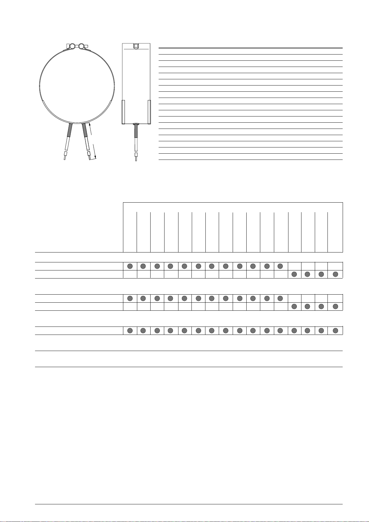
10.3 Riscaldatore olio - Oil heater - Ölheizung
L
10.4 Accessori - Accessories - Zubehör
Dati tecnici - Technical data - Technische Daten
alimentazione elettrica - supply - Elektroanschluß 230 V
potenza - power - Leistung 300 W
corrente assorbita - input current - Betriebstrom 1.37 A
grado di protezione - safety class - Schutzklasse IP54
L lunghezza cavi di alimentazione - cable length - Kabellänge 1500 mm
Modello del compressore - Compressor model - Verdichtermodel
C-TSH8 30 120 Y
C-TSH8 40 120 Y
C-TSH8 40 150 Y
C-TSH8 50 150 Y
C-TSH8 50 186 Y
raffreddatore d’olio ad acqua - water cooled oil cooler - Wassergekühlter Ölkühler
FTEC11-01
raffreddatore d’olio ad aria - air cooled oil cooler - Luftgekühlter Ölkühler
kit circuito olio - oil piping kit - Ölleitungskit
kit economizzatore - economizer kit - Economizer Satz
kit iniezione liquido - liquid injection kit - Flüssigkeitsspritzung Satz
SZ-WOC1
SZ-W0C2
SZ-A0C1
SZ-A0C2
T00WK100
composto da filtro olio, flussostato, valvola elettromagnetica, indicatore di passaggio, modulo elettronico per flussostato
complete with oil filter, flow switch, solenoid valve, oil sight glass, electronic module for flow switch
Komplett mit Ölfilter, Strömungswächter, Magnetventil, Ölschauglas, Elektromodul für Strömungswächter
prestazioni e modelli a richiesta
performances and models on request
Modell und Ausführung auf Anfrage
C-TSH8 60 186 Y
C-TSH8 60 210 Y
C-TSH8 70 210 Y
C-TSH8 70 240 Y
C-TSH8 80 240 Y
C-TSH8 80 270 Y
C-TSH8 90 270 Y
C-TSH8 90 300 Y
C-TSH8 100 300 Y
C-TSH8 100 360 Y
C-TSH8 120 360 Y
21
Page 22
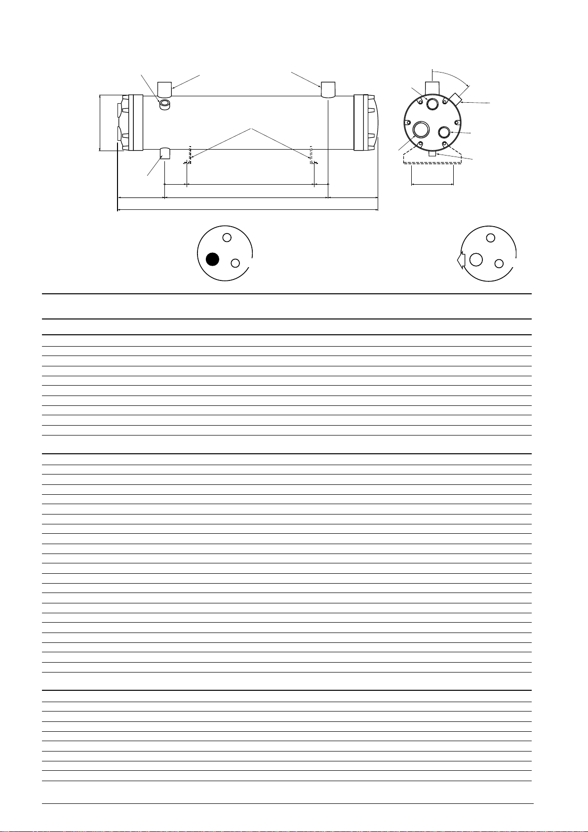
➧
➧
10.5 Raffreddatore d’olio ad acqua - Water cooled oil cooler - Wassergekühlter Ölkühler
➧
➧
3
B
4
D
Collegamento per alimentazione con acqua di pozzo
Connection for mains water supply
Verbindung zur Versorgung mit Stadtwasser
1
a richiesta - on request - auf anfrage
HG
C
A
5
6
7
2
Collegamento per alimentazione con acqua di torre evaporativa
5
6
I
E
Connection for cooling tower water supply
Verbindung zur Versorgung mit Kühlturmwasser
45°
3
7
4
F
5
6
modello - model - Modell
SZ-W0C1 SZ-W0C2 SZ-W0C3
Dimensioni - Dimensions - Abmessungen
A 910 910 1710
B 170 195 170
C 700 700 1500
D 105 105 105
E 105 105 105
F 160 220 160
G 25 25 125
H 550 550 1150
I 25 25 125
7
FTEC11-01
Dati tecnici - Technical data - Technische Daten
∆t H2O 15 ÷ 25°C capacità di raffreddamento - cooling capacity - Kälteleistung * kW 24 38 48
∆t H2O 40 ÷ 50°C capacità di raffreddamento - cooling capacity - Kälteleistung * kW 10.3 18.6 29.8
portata d’olio - oil flow - Ölumlauf min m3/h 0.7 1.4 2.1
volume interno lato olio - oil side internal volume - Ölinnenvolumen l 10.4 13.1 20.0
massima pressione di impiego lato olio - oil side maximum operating pressure - Maximaler Betriebsdruck ölseitig bar 28 28 28
massima pressione di impiego lato acqua - water side maximum operating pressure - Maximaler Betriebsdruck wasserseitig bar 10 10 10
peso - weight - Gewicht kg 39 55 77
* dati di riferimento - reference data - Bezugsdaten
temperatura ingresso olio - oil inlet temperature - Öleintemperatur +95°C
temperatura uscita olio - oil outlet temperature - Ölaustrittemperatur +70°C
fattore di sporcamento - fouling factor - Verschmutzungsfaktor 0
Attacchi - Connections - Anschlüsse
1 ingresso olio - oil inlet - Öleinlaß Ø esterno - Ø outside - Ø außen 42.4 mm 48.3 mm 60.3 mm
2 uscita olio - oil outlet - Ölauslaß Ø esterno - Ø outside - Ø außen 42.4 mm 48.3 mm 60.3 mm
3 attacco per valvola di sicurezza - safety valve connection - Anschluß für Sicherheitsventil 1/2” NPT 1/2” NPT 1/2” NPT
4 attacco per valvola di servizio - service valve connection - Anschluß für Serviceventil 1/2” NPT 1/2” NPT 1/2” NPT
5 attacco acqua - water connection - Wasseranschluß 3/4” NPT 1.1/4” NPT 1” NPT
6 attacco acqua- water connection - Wasseranschluß 1.1/4” NPT 1.1/2” NPT 1.1/2” NPT
7 attacco acqua - water connection - Wasseranschluß 3/4” NPT 1.1/4” NPT 1” NPT
portata d’acqua - water flow - Wassermenge m3/h 1.6 2.0 3.6
perdita di carico - pressure drop - Druckabfall bar 0.23 0.22 0.25
portata d’acqua - water flow - Wassermenge m3/h 1.6 2.0 3.6
perdita di carico - pressure drop - Druckabfall bar 0.23 0.22 0.25
max m3/h 1.4 2.2 3.8
Ø interno - Ø inside - Ø innen 39.4 mm 42.4 mm 53.9 mm
Ø interno - Ø inside - Ø innen 39.4 mm 42.4 mm 53.9 mm
22
Page 23
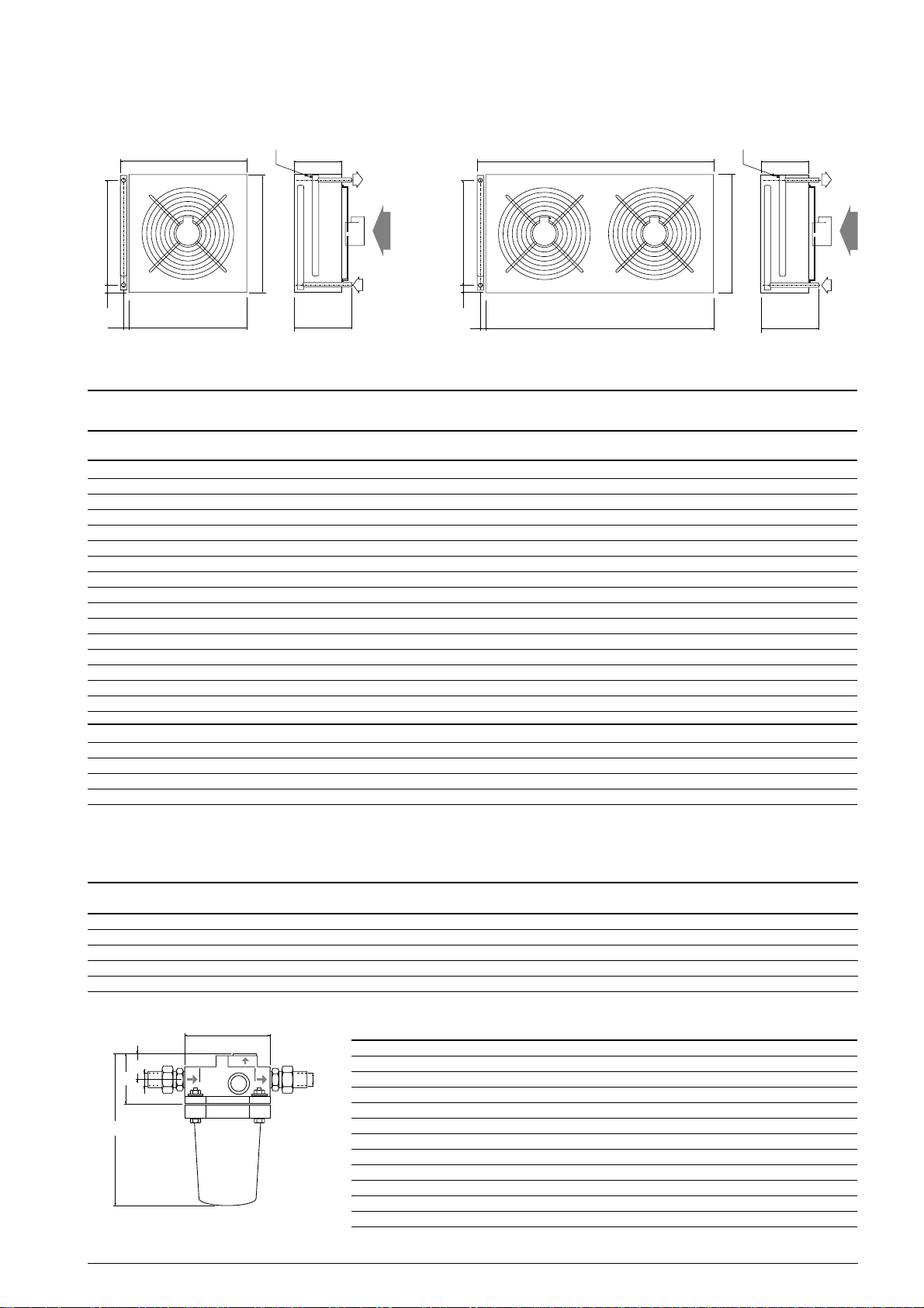
10.6 Raffreddatore d’olio ad aria - Air cooled oil cooler - Luftgekühlter Ölkühler
valvola Schrader
Schrader valve
Schrader-V entil
790
C
A
B
730
1/4” SAE
720
300
350
OIL
C
OIL
A
B
- 1 -
1450
1380
- 2 -
valvola Schrader
Schrader valve
Schrader-V entil
1/4” SAE
720
300
OIL
OIL
350
modello - model - Modell
SZ-A0C1 SZ-A0C2 SZ-A0C3
Dati tecnici - Technical data - Technische Daten
disegno - drawing - Zeichnung 112
capacità frigorifera - cooling capacity - Kälteleistung * kW 11.7 18.2 31.5
volume lato olio - oil side inner volume - Ölinnervolumen l 2.85 4.26 8.53
portata di aria - air flow - Luftstrom m3/h 5200 5000 10000
motoventilatori prementi - inlet motorfans - Ventilatoren n° 112
Ø ventole - Ø fan - Flügel Ø mm 450 450 450
alimentazione elettrica - supply - Elektroanschluß 230-380/3/50 230-380/3/50 230-380/3/50
potenza assorbita totale - total input power - Anschlußwert Total kW 0.45 0.45 0.90
* dati di riferimento - reference data - Bezugsdaten
temperatura ingresso aria - air inlet temperature - Temperatur Lufteintritt +43° C
temperatura ingresso olio - oil inlet temperature - Öleintrittstemperatur +95°C
temperatura uscita olio - oil outlet temperature - Ölaustrittstemperatur +70°C
FTEC11-01
Dimensioni - Dimensions - Abmessungen
A 50.5 mm 50.5 mm 50.5 mm
B 42.5 mm 42.5 mm 52.5 mm
C 619 mm 600 mm 600 mm
OIL attacchi a saldare - solder connections - Lötanschlüsse Ø 22 mm Ø 22 mm Ø 22 mm
10.7 Filtro olio - Oil strainer - Ölfilter
Modello - Model - Modell T00WK110
Dati tecnici - Technical data - Technische Daten
massima pressione di impiego - max working pressure - Maximaler Betriebsdruck 25 bar
massima temperatura di impiego - max working temperature - Maximale Betriebstemperatur 120°C
grado di filtrazione - screening - Filter 25 µm
A
D
C
E
B
Dimensioni - Dimensions - Abmessungen
A 120 mm
B 190 mm
E
C 70 mm
D 36 mm
E attacchi a saldare - solder connections - Lötanschlüsse Ø 22 mm
23
Page 24
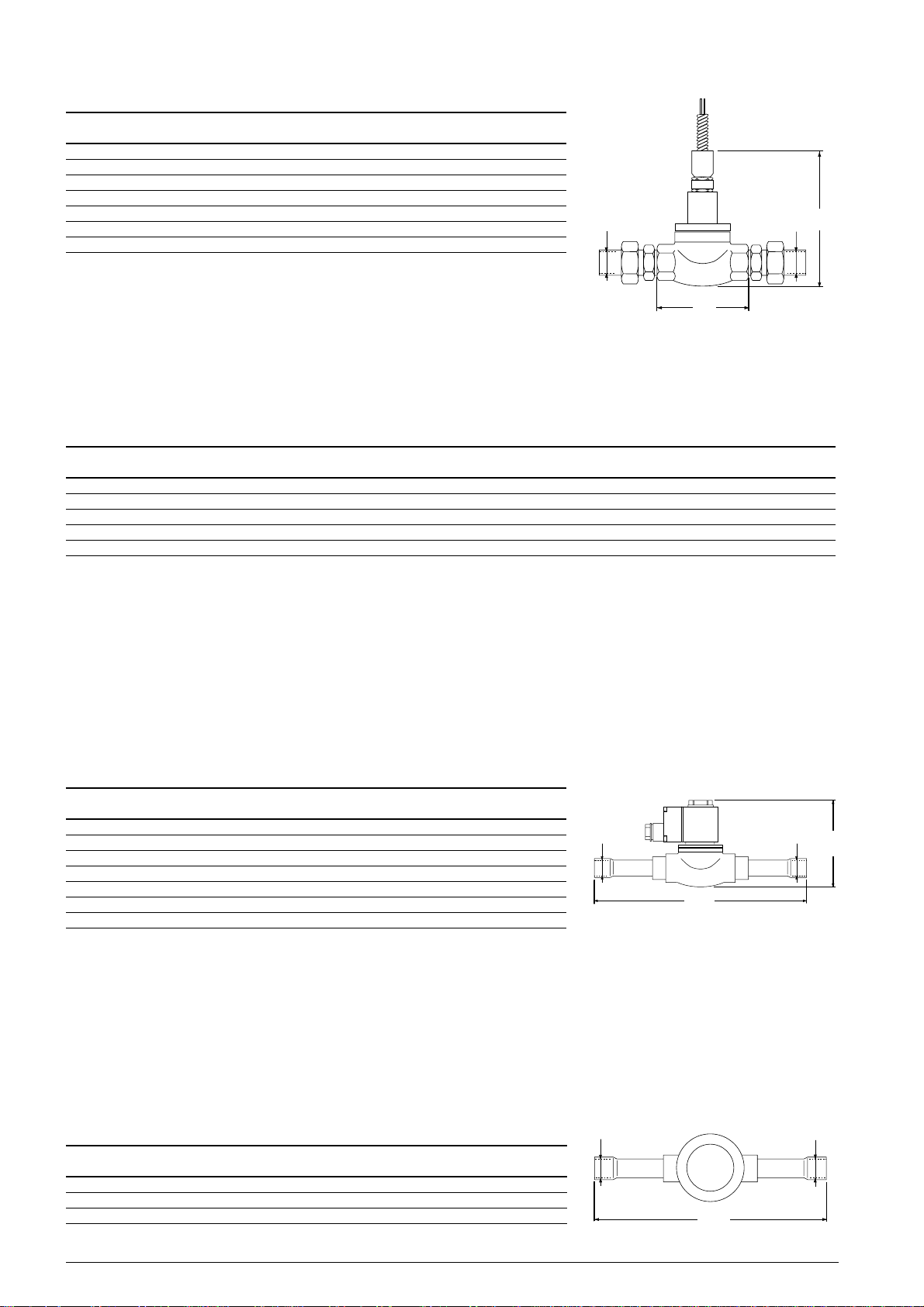
10.8 Flussostato - Flow switch - Strömungswächter
Modello - Model - Modell T00WK130
Dati tecnici - Technical data - Technische Daten
minima portata di chiusura contatti - minimum cut-in flow rate 4 l/min (15 cSt)
massima pressione di impiego - max working pressure - Max. Betriebsdruck 28 bar
massima temperatura di impiego - max working temperature - Max. Betriebstemperatur 110°C
grado di protezione - safety class - Schutzklasse IP65
potenza assorbita 220V - input power 220V - Anschluß 220V 10 W
massima capacità di commutazione 220V - max switching 220V - Max. Schaltleistung bei 220V 0.15 A
attacchi a saldare - solder connections - Lötanschlüsse Ø 22 mm
Ø 22 mm
100
Ø 22 mm
10.9 Modulo elettronico per flussostato - Electronic module for flow switch - Elektromodul für Strömungswächter
Modello - Model - Modell T00EC28
Dati tecnici - Technical data - Technische Daten
alimentazione elettrica - supply - Elektroanschluß 230V 50/60 Hz
potenza assorbita - input power - Anschlußwert < 3 VA
caratteristiche del relay - relay output - Relaisausgang AC 250 V
massima capacità di commutazione 220V - max switching 220V - Schaltleistung Relais bei 220V 5 A
durata operativa, cicli - service life, cycles - Lebensdauer, Schaltspiel 1 x 10
76
6
10.10 Valvola elettromagnetica - Solenoid valve - Magnetventil
Modello - Model - Modell T00WK120
Dati tecnici - Technical data - Technische Daten
massima pressione di impiego - max working pressure - Max. Betriebsdruck 35 bar
massima temperatura di impiego - max working temperature - Max. Betriebstemperatur 105°C
MOPD 21 bar
alimentazione elettrica - supply - Elektroanschluß 220/230 V 50/60 Hz
potenza assorbita - input power -Stromaufnahme 10 W
grado di protezione - safety class - Schutzklasse IP65
attacchi a saldare - solder connections - Lötanschlüsse Ø 22 mm
Ø 22 mm
176
Ø 22 mm
FTEC11-01
105
10.11 Indicatore di passaggio olio - Oil sight glass - Ölschauglas
Modello - Model - Modell T00S0S7
Dati tecnici - Technical data - Technische Daten
massima pressione di impiego - max working pressure - Max. Betriebsdruck 28 bar
massima temperatura di impiego - max working temperature - Max. Betriebstemperatur 100°C
attacchi a saldare - solder connections - Lötanschlüsse Ø 22 mm
24
Ø 22 mm
Ø 22 mm
185
Page 25
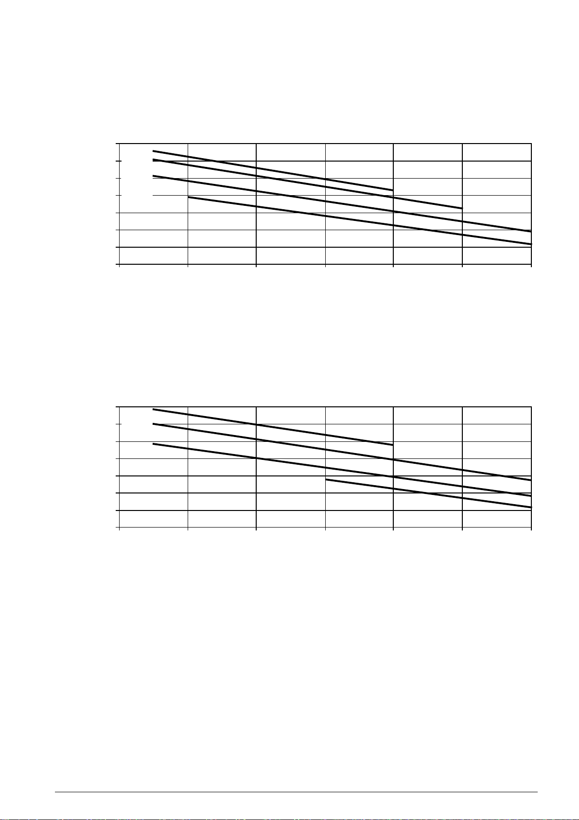
10.12 Temperature intermedie di saturazione - Intermediate saturation temperature - Mitteldrucktemperatur
10
5
0
-5
-10 -15
+10
+30
+20
tc = 55°C
Temperatura intermedia di saturazione °C
Intermediate saturated temperature °C
Gesättigte Mitteldrucktemperatur °C
Temperatura di evaporazione °C - Evaporating temperature °C - Verdampfungstemperatur °C
tc = 50°C
tc = 40°C
tc = 30°C
10
5
0
-5
-10 -15
+10
+30
+20
tc = 60°C
tc = 40°C
tc = 30°C
Temperatura intermedia di saturazione °C
Intermediate saturated temperature °C
Gesättigte Mitteldrucktemperatur °C
Temperatura di evaporazione °C - Evaporating temperature °C - Verdampfungstemperatur °C
tc = 50°C
Refrigerante - Refrigerant - Kältemittel R407C / R22
Refrigerante - Refrigerant - Kältemittel R134a
FTEC11-01
I valori riportati nelle tabelle sono stati calcolati alle seguenti
condizioni:
- surriscaldamento gas aspirato 10K
- tolleranza dei valori nominali ± 5%
dopo 72 ore di funzionamento continuo
dal primo avviamento
tc = temperatura di condensazione
Performance data shown are based on the following
conditions:
- suction gas overheating 10K
-tollerance on nominal values ± 5%
after 72 hours run in
tc = condensing temperature
Die gezeigten Leistungswerte basieren auf den folgenden
Bedingungen:
- Sauggasüberhitzung 10K
-Tolleranzbereich ± 5% dann 72 Stunden
von Dauerbetrieb
tc = Verflüssigungstemperatur
25
Page 26
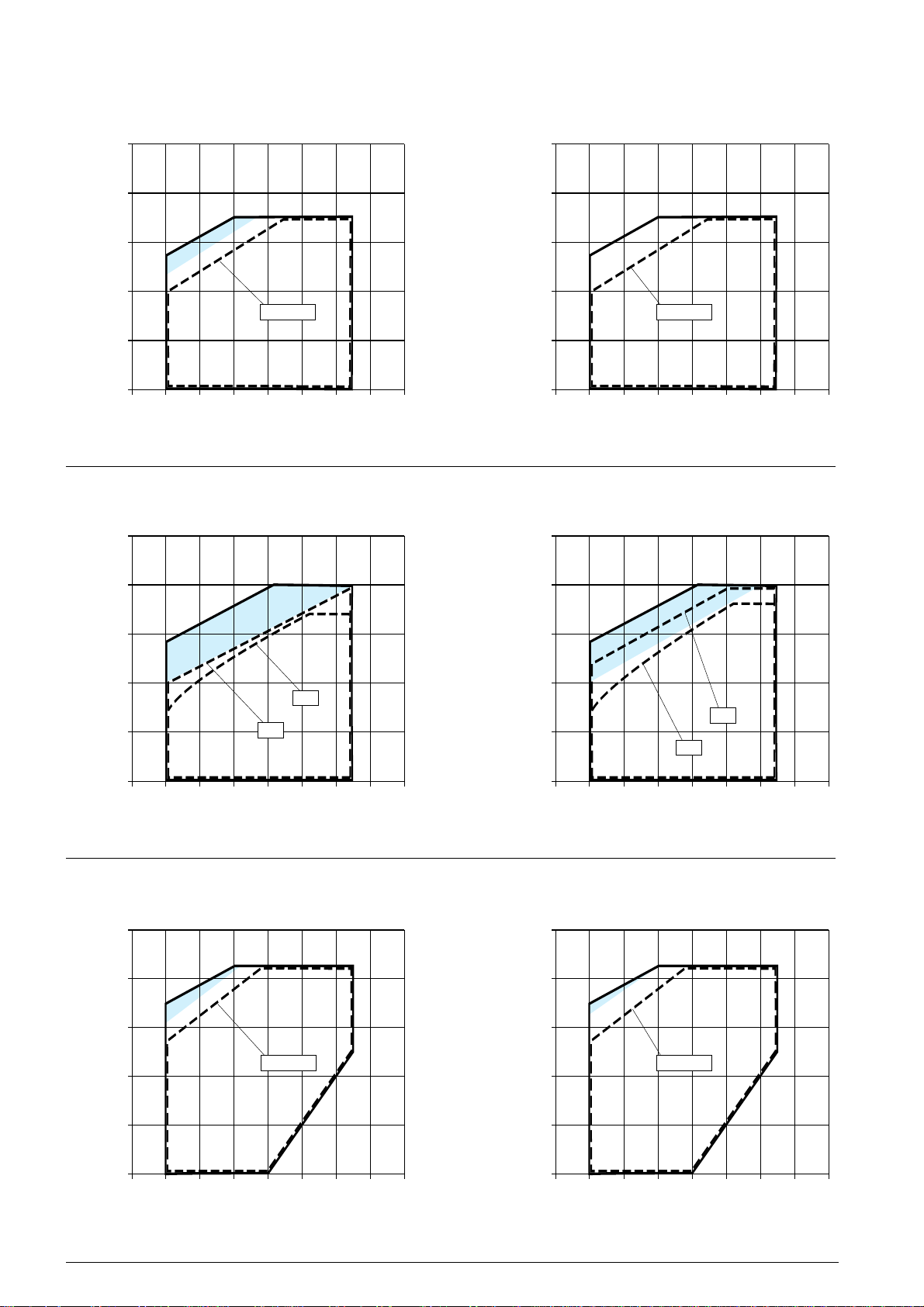
10.13 Campo di applicazione - Application limit - Anwendungsgrenzen
senza economizzatore - without economizer
tc °C70
60
50
40
Verflüssigungstemperatur
30
20
temperatura di condensazione - condensing temperature
tc °C70
-15 -10 -5 0 5 10 15
temperatura di evaporazione - evaporating temperature
senza economizzatore - without economizer
ohne Economizer
te °C
Verdampfungstemperatur
ohne Economizer
R407C
R22
con economizzatore - with economizer
tc °C70
60
50
40
Verflüssigungstemperatur
30
20
temperatura di condensazione - condensing temperature
tc °C70
-15 -10 -5 0 5 10 15
temperatura di evaporazione - evaporating temperature
con economizzatore - with economizer
mit Economizer
50 - 75%50 - 75%
te °C
Verdampfungstemperatur
mit Economizer
60
50
40
Verflüssigungstemperatur
30
temperatura di condensazione - condensing temperature
20
-15 -10 -5 0 5 10 15
temperatura di evaporazione - evaporating temperature
senza economizzatore - without economizer
tc °C70
60
50
50%
te °C
Verdampfungstemperatur
ohne Economizer
75%
R134a
60
50
40
Verflüssigungstemperatur
30
50%
temperatura di condensazione - condensing temperature
20
-15 -10 -5 0 5 10 15
temperatura di evaporazione - evaporating temperature
con economizzatore - with economizer
tc °C70
60
50
te °C
Verdampfungstemperatur
mit Economizer
FTEC11-01
75%
40
Verflüssigungstemperatur
30
20
temperatura di condensazione - condensing temperature
-15 -10 -5 0 5 10 15
temperatura di evaporazione - evaporating temperature
te °C
Verdampfungstemperatur
26
40
Verflüssigungstemperatur
30
20
temperatura di condensazione - condensing temperature
-15 -10 -5 0 5 10 15
temperatura di evaporazione - evaporating temperature
50 - 75%50 - 75%
te °C
Verdampfungstemperatur
Page 27

I limiti di impiego sono stati calcolati alle seguenti condizioni:
senza economizzatore
- surriscaldamento gas aspirato 10K
- senza sottoraffreddamento del liquido
con economizzatore
- surriscaldamento gas aspirato 10K
- sottoraffreddamento del liquido = tm +10K
R407C - Le temperaturedi evaporazione e di condensazione
considerate sono relative al vapore saturo, in conformità con
la norma EN 129000.
- tolleranza dei valori nominali ± 5%
dopo 72 ore di funzionamento continuo dal primo
avviamento
Application limits are based on the following conditions:
without economizer
- suction gas overheating 10K
- without liquid subcooling
with economizer
- suction gas overheating 10K
- liquid subcooling
R407C - Evaporating and condensing temperatures are
based on dew temperature, according to EN 129000
standard.
-tollerance on nominal values ± 5% after 72 hours run in
= tm +10K
Anwendungsgrenzen basieren auf den folgenden
Bedingungen:
ohne Economizer
- Sauggasüberhitzung 10K
- ohne Flüssigkeitsunterkühlung
mit Economizer
- Sauggasüberhitzung 10K
- Flüssigkeitsunterkühlung
R407C - Verdampfungs- und Verflüssigungstemperaturen
beziehen sich auf Taupunkt-Werte, erfüllen die Forderung
EN 129000
-Tolleranzbereich ± 5% dann 72 Stunden von Dauerbetrieb
= tm +10K
te =temperatura di evaporazione
tc =temperatura di condensazione
tm =temperatura di saturazione corrispondente alla
pressione intermedia
funzionamento a pieno
carico (100%)
funzionamento a carico
ridotto (75% e/o 50%)
con iniezione di liquido
oppure raffreddatore d'olio
FTEC11-01
te =evaporating temperature
tc =condensing temperature
tm=saturation temperature related to the intermediate
pressure
full load operation
(100%)
part load operation
(75% and/or 50%)
with liquid injection
or oil cooler
te =Verdampfungstemperatur
tc =Verflüssigungstemperatur
tm =Sättigungstemperatur entspreched der Zwischendruck
Vollastbetrieb
(100%)
Teillastbetrieb
(75% und/oder 50%)
mit Flüssigkeitseinspritzung
oder Ölkühler
27
Page 28
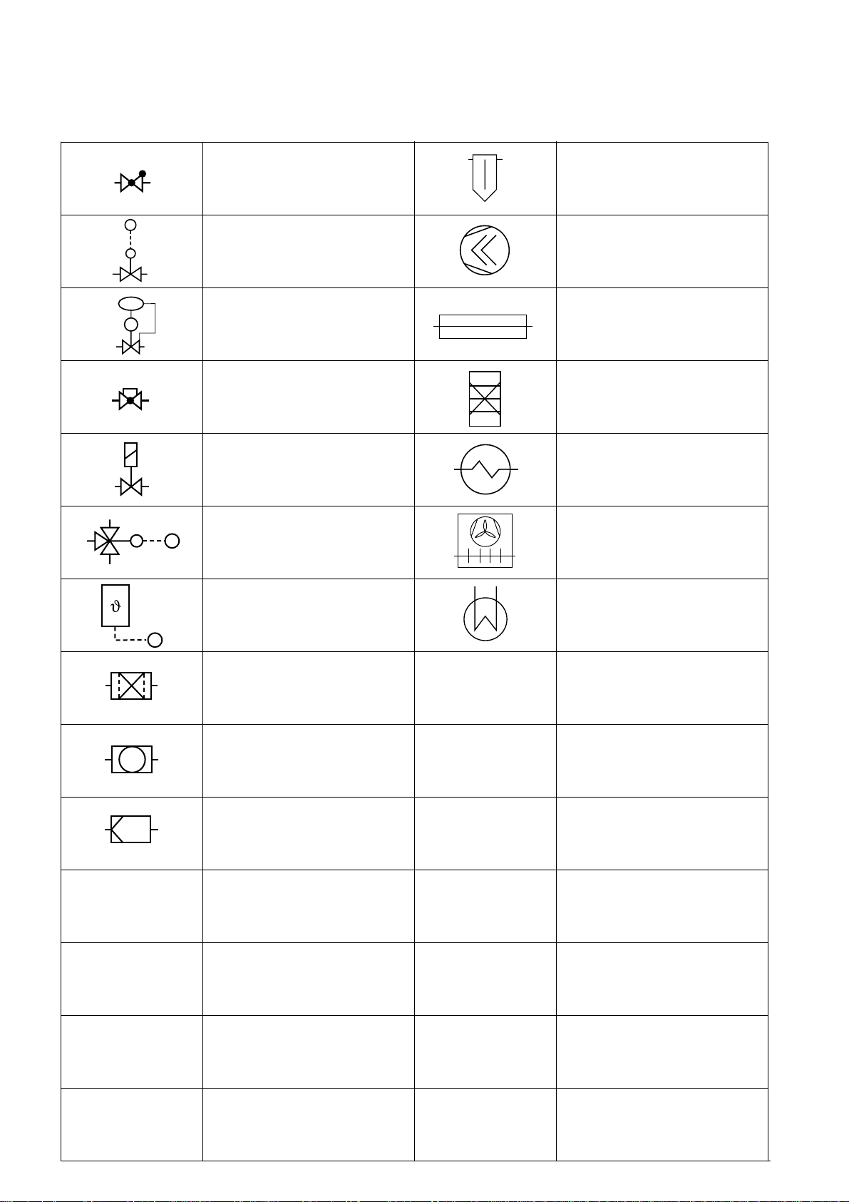
10.14 Simboli - Symbols - Symbole
valvola di ritegno
check valve
Rückschlagdurchgangsventil
valvola termostatica
thermostatic expansion valve
Thermostatisches Expansionventil
valvola regolatrice di pressione
pressure regulating valve
Druckregelventil
valvola di intercettazione
shut-off valve
Absperrdurchgangsventil
valvola elettromagnetica
solenoid valve
Magnetventil
valvola miscelatrice
mixing valve
Mischventil
regolatore di temperatura
separatore d’olio
oil separator
Ölabscheider
compressore a vite
screw compressor
Schraubenverdichter
scambiatore di calore ad acqua
water cooled heat exchanger
Wassergekühlter Wärmetauscher
scambiatore di calore a piastre
plate heat exchanger
Plattenwärmetauscher
scambiatore di calore in controcorrente
crossflow heat exchanger
Gegenstrom Wärmetauscher
scambiatore di calore ad aria
air cooled heat exchanger
Luftgekühlter Wärmetauscher
scambiatore di calore (generico)
FTEC11-01
temperature regulator
Temperaturregler
filtro con cartuccia solida
filter with solid core
Feststofffilter
spia di passaggio
sight glass
Schauglas
filtro di aspirazione
suction filter
Saugfilter
heat exchanger (general)
Genereller Wärmetauscher
28
Page 29

10.15 Dati di prestazione - Performance data - Leistungsdaten
I dati di prestazione sono stati calcolati alle
seguenti condizioni di funzionamento:
senza economizzatore
• surriscaldamento gas aspirato 10K
• senza sottoraffreddamento del liquido
con economizzatore
• surriscaldamento gas aspirato 10K
• sottoraffreddamento del liquido = tm + 10K
• tolleranza dei valori nominali ± 5%, dopo
72 ore di funzionamento dal primo
avviamento
Legenda
tm temperatura di saturazione corrispondente
alla pressione intermedia
Qocapacità frigorifera W
Pepotenza assorbita kW
Performance data shown are based on the
following conditions:
without economizer
• suction gas overheating 10K
• without liquid subcooling
with economizer
• suction gas overheating 10K
• liquid subcooling = tm +10K
• tollerance on nominal values ± 5%
after 72 hours run in
Legend
tm saturation temperature related to the
intermediate pressure
Qocooling capacity W
Peinput power kW
DieLeistungswerte basieren auf den folgenden
Bedingungen:
ohne Economizer
• Sauggasüberhitzung 10K
• ohne Flüssigkeitsunterkühlung
mit Economizer
• Sauggasüberhitzung 10K
• Flüssigkeitsunterkühlung = tm +10K
• Tolleranzbereich ± 5% dann 72 Stunden
von Dauerbetrieb
Legende
tm Sättigungstemperatur entspreched
der Zwischendruck
QoKälteleistung W
PeLeistungsaufnahme kW
FTEC11-01
I
corrente assorbita A
B
m
portata ponderale kg/h
I
input current A
B
m
mass flow kg/h
I
Stromaufnahme A
B
m
Massenstrom kg/h
29
Page 30
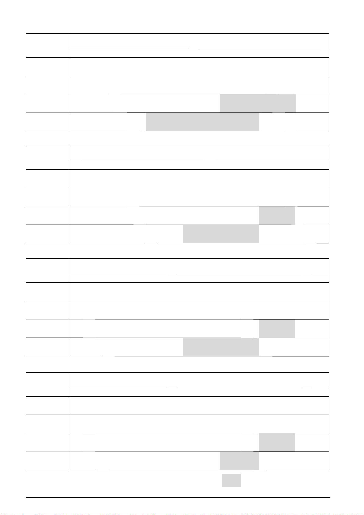
C-TSH8-40 120 Y senza economizzatore - without economizer - ohne Economizer R407C 50Hz
Condensazione
Condensing
Verflüssigungs-
temperatur
°C
30
40
50
55
Q
o
P
e
I
B
m
Q
o
P
e
I
B
m
Q
o
P
e
I
B
m
Q
o
P
e
I
B
m
Temperatura di evaporazione Evaporating temperature Verdampfungstemperatur
°C °C °C
12.5 10 5 0 -5 -10 -15
139480 117740 98970 82820 69010 57280
27.27 25.51 23.86 22.42 21.22 20.42
42.4 39.6 37.1 35.0 33.3 32.2
138350 127180 107100 89800 74920 62220 51450
30.80 30.10 28.61 27.04 25.66 24.50 23.77
48.3 47.1 44.6 42.1 39.8 38.0 36.9
2846.8 2637.6 2257.7 1925.6 1635.8 1384.2 1167.0
122920 112830 94700 79100 65730 54320
36.81 35.79 33.88 32.28 31.12 30.63
58.0 56.5 53.6 50.8 48.8 48.0
2830.4 2620.9 2240.5 1907.9 1617.6 1365.5
114140 104700 87780 73230 60760
39.36 38.62 37.14 35.78 34.81
61.7 60,. 58.5 56.5 55.0
2807.2 2599.4 2222.3 1892.6 1604.8
2631.1 2254.1 1924.5 1636.9 1387.3 1171.8
C-TSH8-50 150 Y senza economizzatore - without economizer - ohne Economizer R407C 50Hz
Condensazione
Condensing
Verflüssigungs-
temperatur
°C
30
40
50
55
Q
o
P
e
I
B
m
Q
o
P
e
I
B
m
Q
o
P
e
I
B
m
Q
o
P
e
I
B
m
Temperatura di evaporazione Evaporating temperature Verdampfungstemperatur
°C °C °C
12.5 10 5 0 -5 -10 -15
173380 146390 123100 103060 85920 71350
29.30 28.15 26.88 25.71 24.76 24.29
48.1 46.6 44.8 43.0 41.6 40.9
172150 158250 133270 111740 93240 77440 64030
35.16 34.65 33.38 31.88 30.42 29.14 28.28
56.3 55.6 53.8 51.7 49.7 47.9 46.7
3542.3 3281.9 2809.3 2396.2 2035.6 1722.6 1452.4
152940 140390 117840 98430 81790 67600
42.56 41.52 39.57 37.87 36.66 36.24
67.0 65.6 62.8 60.3 58.5 57.9
3521.8 3261.1 2787.8 2374.0 2012.9 1699.2
142010 130270 109220 91120 75600
45.65 44.82 43.21 41.80 40.99
71.3 70.1 67.9 65.9 64.8
3492.7 3234.3 2765.1 2354.9 1996.8
3270.6 2802.7 2393.8 2036.9 1727.2 1459.8
C-TSH8-60 186 Y senza economizzatore - without economizer - ohne Economizer R407C 50Hz
Condensazione
Condensing
Verflüssigungs-
temperatur
°C
30
40
50
55
Q
o
P
e
I
B
m
Q
o
P
e
I
B
m
Q
o
P
e
I
B
m
Q
o
P
e
I
B
m
Temperatura di evaporazione Evaporating temperature Verdampfungstemperatur
°C °C °C
12.5 10 5 0 -5 -10 -15
214110 180600 151680 126790 105510 87420
36.97 34.55 32.66 31.40 30.97 32.03
66.1 62.9 60.3 58.7 58.1 59.5
212490 195290 164390 137760 114870 95320 78740
43.53 42.77 41.02 39.13 37.45 36.19 35.77
75.1 74.1 71.7 69.1 66.8 65.1 64.5
4372,3 4050,1 3465.3 2954.1 2507.9 2120.5 1786.1
188930 173390 145490 121480 100880 83330
51.61 50.68 48.74 46.81 45.29 44.61
86.9 85.5 82.6 79.7 77.6 76.7
4350.4 4027.7 3442.0 2929.9 2482.9 2094.7
175250 160720 134650 112240 93040
56.39 55.28 53.29 51.81 51.47
94.4 92.7 89.5 87.2 86.7
4310.4 3990.2 3409.0 2900.9 2457.3
4038.9 3457.6 2949.4 2505.9 2120.9 1788.5
FTEC11-01
C-TSH8-70 210 Y senza economizzatore - without economizer - ohne Economizer R407C 50Hz
Condensazione
Condensing
Verflüssigungs-
temperatur
°C
Q
o
P
30
40
50
55
Qocapacità frigorifera W cooling capacity W Kälteleistung W
Pepotenza assorbita kW input power kW Leistungsaufnahme kW
IBcorrente assorbita A input current A Stromaufnahme A
m portata ponderale kg/h mass flow kg/h Massenstrom kg/h
e
I
B
m 4656.0 3972.1 3374.1 2852.0 2398.5 2006.8
Q
o
P
e
I
B
m 4965.2 4590.9 3911.3 3317.0 2798.1 2347.2 1957.7
Q
o
P
e
I
B
m 4900.9 4530.5 3858.0 3269.8 2756.3 2310.1
Q
o
P
e
I
B
m 4868.6 4503.2 3839.8 3259.7 2753.3
Temperatura di evaporazione Evaporating temperature Verdampfungstemperatur
°C °C °C
12.5 10 5 0 -5 -10 -15
246830 207470 173510 144300 119320 98090
40.10 38.31 36.26 34.25 32.45 31.13
70.2 67.6 64.6 61.8 59.1 56.8
241300 221370 185550 154680 128160 105510 86310
47.40 46.58 44.68 42.56 40.59 39.02 38.26
80.8 79.6 76.8 73.7 70.9 68.6 67.5
212830 195030 163070 135570 111990 91900
57.69 56.48 53.93 51.33 49.09 47.48
96.1 94.3 90.5 86.7 83.3 81.0
197950 181390 151670 126130 104240
63.24 61.96 59.23 56.42 53.90
104.3 102.4 98.4 94.2 90.5
con iniezione di liquido oppure raffreddatore d’olio
with liquid injection or oil cooler
mit Flüssigkeitseinspritzung oder Ölkühler
30
Page 31
C-TSH8-80 240 Y senza economizzatore - without economizer - ohne Economizer R407C 50Hz
Condensazione
Condensing
Verflüssigungs-
temperatur
°C
30
40
50
55
Q
o
P
e
I
B
m
Q
o
P
e
I
B
m
Q
o
P
e
I
B
m
Q
o
P
e
I
B
m
Temperatura di evaporazione Evaporating temperature Verdampfungstemperatur
°C °C °C
12.5 10 5 0 -5 -10 -15
282750 237700 198820 165370 136770 112470
54.24 49.75 45.91 42.77 40.37 39.06
91.1 84.5 78.9 74.5 70.9 68.8
276400 253570 212540 177180 146800 120860 98860
61.46 60.06 57.01 53.79 50.87 48.47 47.10
102.2 100.0 95.3 90.4 86.1 82.6 80.6
5687.5 5258.8 4480.3 3799.5 3205.1 2688.7 2242.4
244070 223640 186960 155400 128340 105280
73.25 71.60 68.11 64.62 61.53 59.11
120.9 118.3 112.8 107.2 102.3 98.5
5620.2 5195.1 4423.2 3748.0 3158.5 2646.4
227000 207990 173870 144540 119420
80.32 77.92 73.49 69.75 67.31
132.3 128.4 121.3 115.3 111.5
5583.2 5163.6 4401.9 3735.7 3154.1
5333.6 4550.7 3866.1 3268.5 2749.3 2300.9
C-TSH8-90 270 Y senza economizzatore - without economizer - ohne Economizer R407C 50Hz
Condensazione
Condensing
Verflüssigungs-
temperatur
°C
30
40
50
55
Q
o
P
e
I
B
m
Q
o
P
e
I
B
m
Q
o
P
e
I
B
m
Q
o
P
e
I
B
m
Temperatura di evaporazione Evaporating temperature Verdampfungstemperatur
°C °C °C
12.5 10 5 0 -5 -10 -15
318430 267660 223840 186150 153920 126530
55.98 52.55 49.26 46.40 44.12 42.85
96.7 91.9 87.3 83.4 80.4 78.7
311290 285570 239330 199480 165240 136020 111220
66.38 64.81 61.46 57.98 54.88 52.43 51.19
112.1 109.7 104.7 99.6 95.2 91.7 90.0
6405.4 5922.2 5045.0 4277.7 3607.8 3025.8 2522.9
274600 251630 210400 174910 144490 118570
78.99 77.05 73.12 69.31 66.19 64.17
131.0 128.1 122.1 116.4 111.8 108.7
6323.1 5845.2 4977.6 4218.7 3556.1 2980.4
255400 234030 195690 162730 134490
86.16 83.91 79.62 75.81 73.13
142.1 138.6 132.0 126.2 122.1
6281.6 5810.1 4954.2 4205.7 3552.2
6006.6 5124.3 4352.7 3679.2 3094.1 2588.7
C-TSH8-100 300 Y senza economizzatore - without economizer - ohne Economizer R407C 50Hz
FTEC11-01
Condensazione
Condensing
Verflüssigungs-
temperatur
°C
30
40
50
55
Q
o
P
e
I
B
m
Q
o
P
e
I
B
m
Q
o
P
e
I
B
m
Q
o
V 94.98 92.43 87.62 83.43 80.55
I
B
m
Temperatura di evaporazione Evaporating temperature Verdampfungstemperatur
°C °C °C
12.5 10 5 0 -5 -10 -15
350990 295000 246680 205110 169570 139360
61.59 57.78 54.18 51.06 48.57 47.21
101.9 96.6 91.6 87.4 83.9 82.0
343110 314760 263800 219870 182140 149930 122600
73.29 71.51 67.75 63.89 60.46 57.76 56.40
119.4 116.6 111.0 105.3 100.3 96.5 94.6
7060.1 6527.6 5560.7 4715.0 3976.7 3335.3 2781.0
302640 277320 231880 192780 159250 130680
86.96 84.83 80.51 76.34 72.87 70.54
140.5 137.3 130.8 124.2 118.7 115.2
6968.7 6442.0 5485.8 4649.5 3919.3 3284.8
281460 257910 215660 179340 148230
152.7 148.8 141.5 135.2 130.8
6922.5 6403.1 5459.9 4635.1 3915.0
6620.9 5647.8 4796.8 4053.9 3408.6 2851.2
C-TSH8-120 360 Y senza economizzatore - without economizer - ohne Economizer R407C 50Hz
Condensazione
Condensing
Verflüssigungs-
temperatur
°C
Q
o
P
30
40
50
55
Qocapacità frigorifera W cooling capacity W Kälteleistung W
Pepotenza assorbita kW input power kW Leistungsaufnahme kW
IBcorrente assorbita A input current A Stromaufnahme A
m portata ponderale kg/h mass flow kg/h Massenstrom kg/h
e
I
B
m
Q
o
P
e
I
B
m
Q
o
P
e
I
B
m
Q
o
P
e
I
B
m
Temperatura di evaporazione Evaporating temperature Verdampfungstemperatur
°C °C °C
12.5 10 5 0 -5 -10 -15
424570 356870 298460 248200 205230 168710
67.70 64.56 61.25 58.24 55.77 54.42
116.8 112.7 108.4 104.5 101.4 99.7
415060 380750 319110 265970 220330 181360 148300
82.41 80.80 77.12 73.03 69.14 65.76 63.44
137.3 135.0 129.7 124.0 118.8 114.2 111.2
8540.5 7896.3 6726.6 5703.6 4810.4 4034.4 3363.9
366530 335850 280770 233370 192730 158100
96.17 94.47 90.83 87.04 83.73 81.33
157.6 155.1 149.7 144.1 139.2 135.7
8440.0 7801.6 6642.4 5628.5 4743.3 3974.1
340530 312040 260920 216970 179320
106.13 103.61 98.79 94.55 91.71
172.4 168.6 161.5 155.3 151.0
8375.4 7746.8 6605.6 5607.6 4736.3
8008.8 6832.4 5803.6 4905.6 4125.5 3451.6
con iniezione di liquido oppure raffreddatore d’olio
with liquid injection or oil cooler
mit Flüssigkeitseinspritzung oder Ölkühler
31
Page 32

C-TSH8-40 120 Y con economizzatore - with economizer - mit Economizer R407C 50Hz
Condensazione
Condensing
Verflüssigungs-
temperatur
°C
30
40
50
55
Q
o
P
e
I
B
m
Q
o
P
e
I
B
m
Q
o
P
e
I
B
m
Q
o
P
e
I
B
m
Temperatura di evaporazione Evaporating temperature Verdampfungstemperatur
°C °C °C
12.5 10 5 0 -5 -10 -15
149030 128010 109530 93350 79270 67080
28.13 26.48 24.97 23.66 22.58 21.92
43.8 41.2 38.8 36.8 35.2 34.2
153430 142440 122390 104740 89250 75740 64030
32.34 31.74 30.44 29.04 27.75 26.73 26.19
50.9 49.9 47.6 45.3 43.2 41.6 40.7
2846.8 2637.6 2257.7 1925.6 1635.8 1384.2 1167.0
144780 134440 115520 98850 84180 71360
40.21 39.30 37.54 36.01 35.00 34.82
62.9 61.6 59.1 56.8 55.3 55.1
2830.4 2620.9 2240.5 1907.9 1617.6 1365.5
139650 129720 111570 95540 81440
43.59 43.37 42.26 41.22 40.60
67.8 67.5 65.9 64.3 63.5
2807.2 2599.4 2222.3 1892.6 1604.8
2631.1 2254.1 1924.5 1636.9 1387.3 1171.8
C-TSH8-50 150 Y con economizzatore - with economizer - mit Economizer R407C 50Hz
Condensazione
Condensing
Verflüssigungs-
temperatur
°C
30
40
50
55
Q
o
P
e
I
B
m
Q
o
P
e
I
B
m
Q
o
P
e
I
B
m
Q
o
P
e
I
B
m
Temperatura di evaporazione Evaporating temperature Verdampfungstemperatur
°C °C °C
12.5 10 5 0 -5 -10 -15
185250 159160 136230 116160 98680 83570
30.25 29.31 28.22 27.23 26.46 26.19
49.4 48.1 46.6 45.3 44.2 43.8
190910 177240 152290 130330 111070 94260 79690
36.96 36.59 35.58 34.31 33.06 31.98 31.35
58.9 58.4 56.9 55.1 53.3 51.8 50.9
3542.3 3281.9 2809.3 2396.2 2035.6 1722.6 1452.4
180140 167280 143750 123000 104740 88800
46.44 45.55 43.80 42.25 41.27 41.28
72.4 71.1 68.7 66.6 65.2 65.2
3521.8 3261.1 2787.8 2374.0 2012.9 1699.2
173750 161410 138830 118880 101340
50.78 50.19 49.05 48.10 47.79
78.6 77.8 76.0 74.6 74.2
3492.7 3234.3 2765.1 2354.9 1996.8
3270.6 2802.7 2393.8 2036.9 1727.2 1459.8
C-TSH8-60 186 Y con economizzatore - with economizer - mit Economizer R407C 50Hz
Condensazione
Condensing
Verflüssigungs-
temperatur
°C
30
40
50
55
Q
o
P
e
I
B
m
Q
o
P
e
I
B
m
Q
o
P
e
I
B
m
Q
o
P
e
I
B
m
Temperatura di evaporazione Evaporating temperature Verdampfungstemperatur
°C °C °C
12.5 10 5 0 -5 -10 -15
228770 196350 167860 142900 121180 102390
38.24 36.04 34.35 33.31 33.15 34.63
67.8 64.9 62.6 61.2 61.0 63.0
235640 218720 187850 160680 136840 116040 98000
45.95 45.37 43.95 42.33 40.91 39.94 39.90
78.5 77.7 75.7 73.5 71.5 70.2 70.1
4372.3 4050.1 3465.3 2954.1 2507.9 2120.5 1786.1
222530 206600 177480 151800 129200 109470
55.98 55.27 53.77 52.29 51.27 51.15
93.8 92.7 90.3 88.0 86.4 86.2
4350.4 4027.7 3442.0 2929.9 2482.9 2094.7
214430 199130 171160 146450 124710
62.31 61.43 59.94 59.02 59.39
104.1 102.7 100.2 98.7 99.3
4310.4 3990.2 3409.0 2900.9 2457.3
4038.9 3457.6 2949.4 2505.9 2120.9 1788.5
FTEC11-01
C-TSH8-70 210 Y con economizzatore - with economizer - mit Economizer R407C 50Hz
Condensazione
Condensing
Verflüssigungs-
temperatur
°C
Q
o
P
30
40
50
55
Qocapacità frigorifera W cooling capacity W Kälteleistung W
Pepotenza assorbita kW input power kW Leistungsaufnahme kW
IBcorrente assorbita A input current A Stromaufnahme A
m portata ponderale kg/h mass flow kg/h Massenstrom kg/h
e
I
B
m
Q
o
P
e
I
B
m
Q
o
P
e
I
B
m
Q
o
P
e
I
B
m
Temperatura di evaporazione Evaporating temperature Verdampfungstemperatur
°C °C °C
12.5 10 5 0 -5 -10 -15
263720 225570 192030 162640 137050 114880
41.45 39.94 38.12 36.31 34.70 33.57
72.1 69.9 67.3 64.7 62.4 60.8
267590 247920 212030 180420 152660 128440 107410
49.95 49.33 47.77 45.95 44.26 42.98 42.58
84.6 83.7 81.4 78.7 76.2 74.3 73.8
4965.2 4590.9 3911.3 3317.0 2798.1 2347.2 1957.7
250690 232390 198930 169410 143430 120720
62.67 61.71 59.58 57.37 55.51 54.35
103.5 102.0 98.9 95.6 92.8 91.1
4900.9 4530.5 3858.0 3269.8 2756.3 2310.1
242200 224730 192790 164560 139730
70.13 69.09 66.83 64.45 62.36
114.9 113.2 109.7 106.1 103.0
4868.6 4503.2 3839.8 3259.7 2753.3
4656.0 3972.1 3374.1 2852.0 2398.5 2006.8
con iniezione di liquido oppure raffreddatore d’olio
with liquid injection or oil cooler
mit Flüssigkeitseinspritzung oder Ölkühler
32
Page 33
C-TSH8-80 240 Y con economizzatore - with economizer - mit Economizer R407C 50Hz
Condensazione
Condensing
Verflüssigungs-
temperatur
°C
30
40
50
55
Q
o
P
e
I
B
m
Q
o
P
e
I
B
m
Q
o
P
e
I
B
m
Q
o
P
e
I
B
m
Temperatura di evaporazione Evaporating temperature Verdampfungstemperatur
°C °C °C
12.5 10 5 0 -5 -10 -15
302100 258430 220030 186380 157090 131720
56.06 51.85 48.25 45.33 43.16 42.15
93.9 87.5 82.3 78.1 75.0 73.6
306520 283990 242870 206660 174870 147130 123040
64.72 63.54 90.89 58.02 55.40 53.32 52.35
107.3 105.5 101.3 96.9 92.9 89.7 88.3
5687.5 5258.8 4480.3 3799.5 3205.1 2688.7 2242.4
287480 266480 228070 194180 164360 138300
79.86 78.51 75.52 72.36 69.57 67.55
131.6 129.4 124.5 119.5 115.1 111.9
5620.2 5195.1 4423.2 3748.0 3158.5 2646.4
277750 257690 221000 188590 160070
89.54 87.36 83.36 80.08 78.26
147.5 143.9 137.3 131.9 129.0
5583.2 5163.6 4401.9 3735.7 3154.1
5333.6 4550.7 3866.1 3268.5 2749.3 2300.9
C-TSH8-90 270 Y con economizzatore - with economizer - mit Economizer R407C 50Hz
Condensazione
Condensing
Verflüssigungs-
temperatur
°C
30
40
50
55
Q
o
P
e
I
B
m
Q
o
P
e
I
B
m
Q
o
P
e
I
B
m
Q
o
P
e
I
B
m
Temperatura di evaporazione Evaporating temperature Verdampfungstemperatur
°C °C °C
12.5 10 5 0 -5 -10 -15
340220 291000 247720 209810 176790 148190
57.86 54.76 51.77 49.18 47.18 46.24
99.4 95.0 90.8 87.2 84.5 83.2
345210 319820 273480 232670 196840 165570 138420
69.98 68.63 65.67 62.56 59.79 57.69 56.92
117.4 115.4 111.0 106.3 102.2 99.2 98.1
6405.4 5922.2 5045.0 4277.7 3607.8 3025.8 2522.9
323430 299830 256650 218570 185050 155760
86.01 84.37 80.97 77.62 74.95 73.51
141.9 139.3 134.1 128.9 124.9 122.7
6323.1 5845.2 4977.6 4218.7 3556.1 2980.4
312490 289950 248730 212320 180270
95.80 93.84 90.13 86.89 84.89
157.3 154.2 148.3 143.2 140.1
6281.6 5810.1 4954.2 4205.7 3552.2
6006.6 5124.3 4352.7 3679.2 3094.1 2588.7
C-TSH8-100 300 Y con economizzatore - with economizer - mit Economizer R407C 50Hz
FTEC11-01
Condensazione
Condensing
Verflüssigungs-
temperatur
°C
30
40
50
55
Q
o
P
e
I
B
m
Q
o
P
e
I
B
m
Q
o
P
e
I
B
m
Q
o
P
e
I
B
m
Temperatura di evaporazione Evaporating temperature Verdampfungstemperatur
°C °C °C
12.5 10 5 0 -5 -10 -15
375020 320730 273000 231180 194760 163220
63.61 60.16 56.88 54.06 51.89 50.92
104.9 99.9 95.3 91.4 88.5 87.2
380500 352510 301440 256460 216970 182510 152590
77.09 75.56 72.26 68.80 65.74 63.42 62.56
125.3 122.9 117.8 112.5 108.0 104.6 103.3
7060.1 6527.6 5560.7 4715.0 3976.7 3335.3 2781.0
356460 330450 282860 240890 203950 171670
94.33 92.51 88.76 85.07 82.08 80.37
151.7 149.0 143.2 137.6 133.1 130.6
6968.7 6442.0 5485.8 4649.5 3919.3 3284.8
344380 319540 274120 234000 198680
105.18 102.87 98.62 95.03 92.90
168.8 165.0 158.3 152.8 149.6
6922.5 6403.1 5459.9 4635.1 3915.0
6620.9 5647.8 4796.8 4053.9 3408.6 2851.2
C-TSH8-120 360 Y con economizzatore - with economizer - mit Economizer R407C 50Hz
Condensazione
Condensing
Verflüssigungs-
temperatur
°C
Q
o
P
30
40
50
55
Qocapacità frigorifera W cooling capacity W Kälteleistung W
Pepotenza assorbita kW input power kW Leistungsaufnahme kW
IBcorrente assorbita A input current A Stromaufnahme A
m portata ponderale kg/h mass flow kg/h Massenstrom kg/h
e
I
B
m
Q
o
P
e
I
B
m
Q
o
P
e
I
B
m
Q
o
P
e
I
B
m
Temperatura di evaporazione Evaporating temperature Verdampfungstemperatur
°C °C °C
12.5 10 5 0 -5 -10 -15
453630 388000 330300 279740 235720 197590
69.88 67.19 64.27 61.62 59.51 58.59
119.7 116.1 112.3 108.8 106.1 105.0
460280 426430 364640 310230 262460 220770 184560
86.62 85.33 82.20 78.58 75.10 72.13 70.28
143.4 141.5 137.0 131.8 126.9 122.8 120.3
8540.5 7896.3 6726.6 5703.6 4810.4 4034.4 3363.9
431720 400190 342500 291610 246830 207690
104.32 103.04 100.10 96.91 94.18 92.51
169.7 167.8 163.4 158.7 154.7 152.3
8440.0 7801.6 6642.4 5628.5 4743.3 3974.1
416650 386610 331650 283090 240370
117.44 115.31 111.25 107.76 105.79
189.5 186.3 180.1 174.8 171.9
8375.4 7746.8 6605.6 5607.6 4736.3
8008.8 6832.4 5803.6 4905.6 4125.5 3451.6
con iniezione di liquido oppure raffreddatore d’olio
with liquid injection or oil cooler
mit Flüssigkeitseinspritzung oder Ölkühler
33
Page 34
C-TSH8-40 120 Y senza economizzatore - without economizer - ohne Economizer R22 50Hz
Condensazione
Condensing
Verflüssigungs-
temperatur
°C
30
40
50
55
Q
o
P
e
I
B
m 2932.9 2518.5 2150.9 1826.7 1541.3 1290.8
Q
o
P
e
I
B
m 3127.8 2901.2 2485.4 2116.5 1791.1 1504.5 1252.9
Q
o
P
e
I
B
m 3040.6 2816.4 2404.8 2039.6 1717.3 1433.3
Q
o
P
e
I
B
m 2972.6 2751.2 2344.7 1983.9 1665.6
Temperatura di evaporazione Evaporating temperature Verdampfungstemperatur
°C °C °C
12.5 10 5 0 -5 -10 -15
147220 125050 105580 88580 73800 60990
26.11 25.44 24.52 23.54 22.53 21.70
40.5 39.5 38.1 36.6 35.1 33.9
146540 135160 114440 96250 80390 66610 54680
31.70 31.28 30.17 28.88 27.64 26.53 25.78
49.8 49.1 47.2 45.0 43.0 41.2 40.0
130920 120520 101600 85010 70560 58020
37.85 37.18 35.68 34.18 32.99 32.23
59.6 58.6 56.4 54.1 52.1 50.7
122070 112250 94390 78740 65120
42.24 41.50 39.85 38.35 37.30
65.8 64.7 62.4 60.3 58.8
C-TSH8-50 150 Y senza economizzatore - without economizer - ohne Economizer R22 50Hz
Condensazione
Condensing
Verflüssigungs-
temperatur
°C
30
40
50
55
Q
o
P
e
I
B
m 3654.1 3135.5 2675.5 2269.9 1912.6 1599.1
Q
o
P
e
I
B
m 3892.7 3610.5 3092.5 2633.0 2227.7 1870.6 1557.2
Q
o
P
e
I
B
m 3782.9 3503.9 2991.7 2537.3 2136.3 1782.9
Q
o
P
e
I
B
m 3697.1 3421.8 2916.7 2468.4 2072.7
Temperatura di evaporazione Evaporating temperature Verdampfungstemperatur
°C °C °C
12.5 10 5 0 -5 -10 -15
183420 155690 131330 110070 91580 75550
30.87 29.75 28.49 27.29 26.20 25.50
50.3 48.7 47.0 45.4 43.8 42.7
182380 168210 142390 119740 99990 82810 67950
36.98 36.54 35.29 33.78 32.26 30.82 29.72
59.0 58.3 56.5 54.4 52.2 50.2 48.7
162880 149940 126400 105760 87780 72170
44.02 43.38 41.83 40.21 38.91 37.97
69.0 68.1 66.0 63.7 61.8 60.4
151820 139620 117420 97970 81040
48.02 47.36 45.81 44.31 43.16
74.5 73.6 71.5 69.4 67.8
C-TSH8-60 186 Y senza economizzatore - without economizer - ohne Economizer R22 50Hz
Condensazione
Condensing
Verflüssigungs-
temperatur
°C
30
40
50
55
Q
o
P
e
I
B
m 4507.2 3866.5 3298.2 2797.0 2355.5 1968.1
Q
o
P
e
I
B
m 4811.0 4462.2 3822.2 3254.5 2753.7 2312.5 1925.2
Q
o
P
e
I
B
m 4670.7 4325.6 3692.2 3130.1 2634.2 2197.0
Q
o
P
e
I
B
m 4576.3 4234.0 3605.9 3048.3 2556.2
Temperatura di evaporazione Evaporating temperature Verdampfungstemperatur
°C °C °C
12.5 10 5 0 -5 -10 -15
226250 191980 161890 135630 112780 92990
38.82 36.34 34.42 33.15 32.58 33.39
68.6 65.3 62.7 61.0 60.2 61.3
225410 207890 175990 148000 123600 102380 84020
46.21 45.43 43.54 41.54 39.76 38.35 37.80
78.9 77.8 75.2 72.4 69.9 68.0 67.2
201110 185110 155990 130470 108240 88930
54.09 53.32 51.47 49.50 47.82 46.58
90.8 89.6 86.7 83.7 81.2 79.4
187930 172760 145160 120990 99940
59.31 58.37 56.32 54.48 53.26
99.2 97.6 94.3 91.4 89.5
FTEC11-01
C-TSH8-70 210 Y senza economizzatore - without economizer - ohne Economizer R22 50Hz
Condensazione
Condensing
Verflüssigungs-
temperatur
°C
Q
o
P
30
40
50
55
Qocapacità frigorifera W cooling capacity W Kälteleistung W
Pepotenza assorbita kW input power kW Leistungsaufnahme kW
IBcorrente assorbita A input current A Stromaufnahme A
m portata ponderale kg/h mass flow kg/h Massenstrom kg/h
e
I
B
m 5198.5 4442.1 3771.0 3178.9 2657.1 2199.0
Q
o
P
e
I
B
m 5453.4 5048.3 4304.8 3645.0 3062.8 2549.6 2098.8
Q
o
P
e
I
B
m 5264.2 4868.3 4141.6 3496.6 2927.2 2425.2
Q
o
P
e
I
B
m 5158.5 4768.7 4053.2 3418.1 2857.5
Temperatura di evaporazione Evaporating temperature Verdampfungstemperatur
°C °C °C
12.5 10 5 0 -5 -10 -15
260950 220560 185100 154150 127220 103900
42.57 40.51 38.26 36.08 34.00 32.34
73.8 70.8 67.5 64.4 61.4 58.9
255500 235190 198210 165770 137470 112870 91590
50.50 49.66 47.49 45.04 42.67 40.48 38.86
85.4 84.2 81.0 77.4 73.9 70.7 68.4
226660 208330 174980 145750 120280 98160
59.77 58.54 55.79 53.00 50.58 48.73
99.2 97.3 93.2 89.1 85.6 82.8
211840 194570 163170 135670 111720
67.39 65.68 62.17 59.00 56.57
110.5 108.0 102.7 98.0 94.4
con iniezione di liquido oppure raffreddatore d’olio
with liquid injection or oil cooler
mit Flüssigkeitseinspritzung oder Ölkühler
34
Page 35
C-TSH8-80 240 Y senza economizzatore - without economizer - ohne Economizer R22 50Hz
Condensazione
Condensing
Verflüssigungs-
temperatur
°C
30
40
50
55
Q
o
P
e
I
B
m 5958.7 5091.5 4322.1 3643.2 3045.0 2519.7
Q
o
P
e
I
B
m 6250.0 5785.5 4933.0 4176.3 3508.6 2920.1 2403.1
Q
o
P
e
I
B
m 6037.8 5583.0 4748.3 4007.5 3353.5 2776.9
Q
o
P
e
I
B
m 5915.3 5468.1 4647.2 3918.5 3275.2
Temperatura di evaporazione Evaporating temperature Verdampfungstemperatur
°C °C °C
12.5 10 5 0 -5 -10 -15
299110 252800 212150 176670 145790 119050
57.52 53.03 49.09 45.73 42.85 40.81
96.1 89.3 83.5 78.7 74.6 71.6
292830 269540 227130 189930 157480 129270 104870
65.45 63.62 59.82 56.16 53.03 50.56 49.40
108.5 105.6 99.6 94.0 89.3 85.6 83.9
259970 238920 200610 167040 137790 112400
76.82 74.99 71.04 67.20 64.08 61.84
126.7 123.7 117.4 111.3 106.3 102.8
242920 223110 187090 155530 128050
84.70 82.42 77.72 73.46 70.11
139.5 135.8 128.1 121.2 115.9
C-TSH8-90 270 Y senza economizzatore - without economizer - ohne Economizer R22 50Hz
Condensazione
Condensing
Verflüssigungs-
temperatur
°C
30
40
50
55
Q
o
P
e
I
B
m 6708.9 5732.6 4866.3 4102.0 3428.5 2837.1
Q
o
P
e
I
B
m 7032.7 6510.3 5551.5 4700.6 3949.8 3287.9 2706.6
Q
o
P
e
I
B
m 6789.2 6278.7 5341.7 4510.0 3775.9 3128.7
Q
o
P
e
I
B
m 6656.2 6153.3 5230.3 4411.1 3687.8
Temperatura di evaporazione Evaporating temperature Verdampfungstemperatur
°C °C °C
12.5 10 5 0 -5 -10 -15
336760 284640 238870 198920 164160 134050
59.01 55.52 52.19 49.24 46.70 45.04
101.1 96.1 91.4 87.3 83.8 81.6
329500 303300 255610 213770 177280 145560 118120
69.47 68.15 64.99 61.59 58.41 55.60 53.76
116.7 114.7 110.0 104.9 100.2 96.2 93.6
292330 268690 225680 187990 155150 126640
82.89 81.15 77.28 73.35 69.96 67.40
137.0 134.3 128.4 122.5 117.4 113.6
273340 251070 210560 175080 144190
90.81 88.70 84.26 80.17 76.98
149.4 146.1 139.1 132.8 127.9
C-TSH8-100 300 Y senza economizzatore - without economizer - ohne Economizer R22 50Hz
FTEC11-01
Condensazione
Condensing
Verflüssigungs-
temperatur
°C
30
40
50
55
Q
o
P
e
I
B
m 7389.4 6314.1 5360.0 4518.2 3776.4 3125.0
Q
o
P
e
I
B
m 7756.4 7180.1 6122.3 5183.6 4355.3 3625.1 2983.8
Q
o
P
e
I
B
m 7485.2 6922.1 5888.6 4971.2 4161.4 3447.4
Q
o
P
e
I
B
m 7331.4 6778.3 5763.2 4862.1 4066.6
Temperatura di evaporazione Evaporating temperature Verdampfungstemperatur
°C °C °C
12.5 10 5 0 -5 -10 -15
370930 313510 263100 219100 180810 147650
64.85 61.06 57.44 54.23 51.46 49.61
106.7 101.2 96.1 91.7 87.9 85.4
363400 334510 281900 235740 195480 160490 130210
76.79 75.25 71.66 67.85 64.32 61.25 59.27
124.9 122.5 116.9 111.1 105.9 101.4 98.6
322300 296230 248790 207210 170990 139540
91.26 89.45 85.35 81.09 77.30 74.23
147.0 144.3 138.1 131.6 125.7 120.9
301070 276570 232010 192980 159000
99.99 97.66 92.80 88.34 84.88
160.4 156.9 149.4 142.6 137.4
C-TSH8-120 360 Y senza economizzatore - without economizer - ohne Economizer R22 50Hz
Condensazione
Condensing
Verflüssigungs-
temperatur
°C
Q
o
P
30
40
50
55
Qocapacità frigorifera W cooling capacity W Kälteleistung W
Pepotenza assorbita kW input power kW Leistungsaufnahme kW
IBcorrente assorbita A input current A Stromaufnahme A
m portata ponderale kg/h mass flow kg/h Massenstrom kg/h
e
I
B
m 8947.5 7645.0 6489.2 5469.5 4570.9 3781.8
Q
o
P
e
I
B
m 9375.6 8679.3 7401.2 6267.0 5266.1 4383.8 3608.9
Q
o
P
e
I
B
m 9063.7 8381.9 7130.4 6019.6 5039.1 4174.6
Q
o
P
e
I
B
m 8875.3 8204.1 6972.2 5878.6 4913.2
Temperatura di evaporazione Evaporating temperature Verdampfungstemperatur
°C °C °C
12.5 10 5 0 -5 -10 -15
449140 379590 318530 265230 218850 178690
72.39 68.66 64.88 61.40 58.27 56.04
123.2 118.1 113.1 108.5 104.5 101.7
439270 404350 340780 285000 236360 194080 157490
85.38 83.66 79.74 75.72 72.13 69.21 67.81
141.6 139.1 133.5 127.8 122.8 118.8 117.0
390260 358700 301260 250910 207050 168980
100.24 98.53 94.49 90.26 86.47 83.38
163.6 161.1 155.2 148.9 143.2 138.7
364480 334750 280680 233330 192090
112.01 108.72 102.68 98.17 96.18
181.2 176.3 167.2 160.6 157.6
con iniezione di liquido oppure raffreddatore d’olio
with liquid injection or oil cooler
mit Flüssigkeitseinspritzung oder Ölkühler
35
Page 36
C-TSH8-40 120 Y con economizzatore - with economizer - mit Economizer R22 50Hz
Condensazione
Condensing
Verflüssigungs-
temperatur
°C
30
40
50
55
Q
o
P
e
I
B
m
Q
o
P
e
I
B
m
Q
o
P
e
I
B
m
Q
o
P
e
I
B
m
Temperatura di evaporazione Evaporating temperature Verdampfungstemperatur
°C °C °C
12.5 10 5 0 -5 -10 -15
155690 134180 114990 97960 82890 69610
26.77 26.26 25.48 24.62 23.73 23.02
41.6 40.8 39.5 38.2 36.9 35.8
159500 148300 127640 109160 92740 78190 65340
32.98 32.66 31.73 30.61 29.51 28.52 27.91
52.1 51.5 49.9 47.9 46.1 44.4 43.5
3127.8 2901.2 2485.4 2116.5 1791.1 1504.5 1252.9
149030 138450 118870 101350 85760 71910
40.58 40.04 38.73 37.39 36.34 35.76
63.4 62.7 60.8 58.9 57.3 56.5
3040.6 2816.4 2404.8 2039.6 1717.3 1433.3
142750 132540 113650 96720 81640
44.28 43.97 43.49 43.03 42.29
68.0 68.0 67.5 67.0 65.9
2972.6 2751.2 2344.7 1983.9 1665.6
2932.9 2518.5 2150.9 1826.7 1541.3 1290.8
C-TSH8-50 150 Y con economizzatore - with economizer - mit Economizer R22 50Hz
Condensazione
Condensing
Verflüssigungs-
temperatur
°C
30
40
50
55
Q
o
P
e
I
B
m
Q
o
P
e
I
B
m
Q
o
P
e
I
B
m
Q
o
P
e
I
B
m
Temperatura di evaporazione Evaporating temperature Verdampfungstemperatur
°C °C °C
12.5 10 5 0 -5 -10 -15
193970 167060 143030 121720 102860 86230
31.71 30.77 29.67 28.63 27.69 27.15
51.4 50.1 48.6 47.2 45.9 45.2
198510 184560 158820 135800 115350 97220 81210
38.51 38.19 37.17 35.86 34.52 33.24 32.31
61.2 60.7 59.2 57.3 55.4 53.6 52.3
3892.7 3610.5 3092.5 2633.0 2227.7 1870.6 1557.2
185410 172240 147890 126090 106680 89450
47.15 46.67 45.40 44.01 42.85 42.14
73.3 72.7 70.9 69.0 67.4 66.4
3782.9 3503.9 2991.7 2537.3 2136.3 1782.9
177540 164850 141380 120330 101590
52.29 51.85 50.72 49.60 48.83
80.9 80.3 78.5 76.9 75.7
3697.1 3421.8 2916.7 2468.4 2072.7
3654.1 3135.5 2675.5 2269.9 1912.6 1599.1
C-TSH8-60 186 Y con economizzatore - with economizer - mit Economizer R22 50Hz
Condensazione
Condensing
Verflüssigungs-
temperatur
°C
30
40
50
55
Q
o
P
e
I
B
m
Q
o
P
e
I
B
m
Q
o
P
e
I
B
m
Q
o
P
e
I
B
m
Temperatura di evaporazione Evaporating temperature Verdampfungstemperatur
°C °C °C
12.5 10 5 0 -5 -10 -15
239260 206010 176320 149990 126680 106130
39.96 37.66 35.93 34.85 34.51 35.65
70.2 67.1 64.7 63.3 62.8 64.3
245340 228100 196290 167850 142580 120180 100410
48.28 47.68 46.07 44.30 42.75 41.58 41.34
81.9 81.0 78.7 76.2 74.1 72.4 72.1
4811.0 4462.2 3822.2 3254.5 2753.7 2312.5 1925.2
228930 212640 182510 155550 131540 110230
57.63 57.06 55.57 53.94 52.59 51.78
96.4 95.5 93.1 90.5 88.4 87.2
4670.7 4325.6 3692.2 3130.1 2634.2 2197.0
219760 203970 174780 148610 125290
64.51 63.71 61.94 60.49 59.72
107.8 106.5 103.5 101.1 99.8
4576.3 4234.0 3605.9 3048.3 2556.2
4507.2 3866.5 3298.2 2797.0 2355.5 1968.1
FTEC11-01
C-TSH8-70 210 Y con economizzatore - with economizer - mit Economizer R22 50Hz
Condensazione
Condensing
Verflüssigungs-
temperatur
°C
Q
o
P
30
40
50
55
Qocapacità frigorifera W cooling capacity W Kälteleistung W
Pepotenza assorbita kW input power kW Leistungsaufnahme kW
IBcorrente assorbita A input current A Stromaufnahme A
m portata ponderale kg/h mass flow kg/h Massenstrom kg/h
e
I
B
m
Q
o
P
e
I
B
m
Q
o
P
e
I
B
m
Q
o
P
e
I
B
m
Temperatura di evaporazione Evaporating temperature Verdampfungstemperatur
°C °C °C
12.5 10 5 0 -5 -10 -15
275950 236670 201600 170470 142900 118580
43.79 41.96 39.91 37.90 35.97 34.45
75.5 72.9 69.9 67.0 64.2 62.1
278100 258060 221080 188000 158590 132510 109460
52.69 52.02 50.16 47.96 45.79 43.79 42.39
88.7 87.7 84.9 81.7 78.5 75.5 73.5
5453.4 5048.3 4304.8 3645.0 3062.8 2549.6 2098.8
258020 239310 204730 173760 146170 121670
63.77 62.74 60.32 57.82 55.68 54.17
105.1 103.6 100.0 96.3 93.1 90.8
5264.2 4868.3 4141.6 3496.6 2927.2 2425.2
247720 229730 196470 166640 140060
73.48 71.89 68.58 65.67 63.58
120.5 117.8 112.4 108.0 104.8
5158.5 4768.7 4053.2 3418.1 2857.5
5198.5 4442.1 3771.0 3178.9 2657.1 2199.0
con iniezione di liquido oppure raffreddatore d’olio
with liquid injection or oil cooler
mit Flüssigkeitseinspritzung oder Ölkühler
36
Page 37
C-TSH8-80 240 Y con economizzatore - with economizer - mit Economizer R22 50Hz
Condensazione
Condensing
Verflüssigungs-
temperatur
°C
30
40
50
55
Q
o
P
e
I
B
m
Q
o
P
e
I
B
m
Q
o
P
e
I
B
m
Q
o
P
e
I
B
m
Temperatura di evaporazione Evaporating temperature Verdampfungstemperatur
°C °C °C
12.5 10 5 0 -5 -10 -15
316300 271270 231060 195370 163760 135880
59.14 54.91 51.19 48.02 45.33 43.49
98.6 92.1 86.6 81.9 78.1 75.5
318730 295750 253340 215400 181670 151760 125330
68.31 66.61 63.12 59.73 56.84 54.64 53.83
113.1 110.4 104.8 99.5 95.0 91.7 90.5
6250.0 5785.5 4933.0 4176.3 3508.6 2920.1 2403.1
295930 274450 234720 199140 167460 139320
82.23 80.62 77.05 73.52 70.62 68.72
135.4 132.8 127.0 121.3 116.7 113.7
6037.8 5583.0 4748.3 4007.5 3353.5 2776.9
284060 263430 225260 191030 160540
89.96 89.09 86.14 82.15 79.15
148.0 147.8 141.9 135.3 130.4
5915.3 5468.1 4647.2 3918.5 3275.2
5958.7 5091.5 4322.1 3643.2 3045.0 2519.7
C-TSH8-90 270 Y con economizzatore - with economizer - mit Economizer R22 50Hz
Condensazione
Condensing
Verflüssigungs-
temperatur
°C
30
40
50
55
Q
o
P
e
I
B
m
Q
o
P
e
I
B
m
Q
o
P
e
I
B
m
Q
o
P
e
I
B
m
Temperatura di evaporazione Evaporating temperature Verdampfungstemperatur
°C °C °C
12.5 10 5 0 -5 -10 -15
356120 305430 260150 219970 184390 153000
60.68 57.49 54.42 51.72 49.41 48.01
103.6 98.9 94.5 90.7 87.5 85.6
358640 332800 285100 242440 204510 170880 141160
72.54 71.43 68.63 65.53 62.64 60.12 58.62
121.2 119.6 115.4 110.8 106.4 102.7 100.5
7032.7 6510.3 5551.5 4700.6 3949.8 3287.9 2706.6
332760 308650 264050 224120 188550 156970
88.62 87.15 83.72 80.19 77.17 75.04
145.9 143.6 138.3 132.9 128.3 125.0
6789.2 6278.7 5341.7 4510.0 3775.9 3128.7
319640 296440 253520 215040 180760
99.15 97.24 93.20 89.51 86.78
162.8 159.7 153.1 147.3 143.0
6656.2 6153.3 5230.3 4411.1 3687.8
6708.9 5732.6 4866.3 4102.0 3428.5 2837.1
C-TSH8-100 300 Y con economizzatore - with economizer - mit Economizer R22 50Hz
FTEC11-01
Condensazione
Condensing
Verflüssigungs-
temperatur
°C
-
30
40
50
55
Q
o
P
e
I
B
m
Q
o
P
e
I
B
m
Q
o
P
e
I
B
m
Q
o
P
e
I
B
m
Temperatura di evaporazione Evaporating temperature Verdampfungstemperatur
°C °C °C
12.5 10 5 0 -5 -10 -15
392250 336410 286550 242290 203100 168520
66.64 63.17 59.84 56.90 54.38 52.82
109.3 104.2 99.4 95.3 91.9 89.7
395540 367040 314420 267360 225510 188400 155610
80.02 78.71 75.53 72.07 68.86 66.09 64.49
130.0 127.9 122.9 117.5 112.6 108.5 106.1
7756.4 7180.1 6122.3 5183.6 4355.3 3625.1 2983.8
366880 340280 291080 247030 207800 172960
97.26 95.75 92.14 88.31 84.91 82.25
156.2 153.9 148.4 142.6 137.4 133.4
7485.2 6922.1 5888.6 4971.2 4161.4 3447.4
352060 326550 279350 237030 199330
108.90 106.74 102.19 98.14 95.18
174.9 171.3 163.9 157.6 153.0
7331.4 6778.3 5763.2 4862.1 4066.6
7389.4 6314.1 5360.0 4518.2 3776.4 3125.0
C-TSH8-120 360 Y con economizzatore - with economizer - mit Economizer R22 50Hz
Condensazione
Condensing
Verflüssigungs-
temperatur
°C
Q
o
P
30
40
50
55
Qocapacità frigorifera W cooling capacity W Kälteleistung W
Pepotenza assorbita kW input power kW Leistungsaufnahme kW
IBcorrente assorbita A input current A Stromaufnahme A
m portata ponderale kg/h mass flow kg/h Massenstrom kg/h
e
I
B
m 8947.5 7645.0 6489.2 5469.5 4570.9 3781.8
Q
o
P
e
I
B
m 9375.6 8679.3 7401.2 6267.0 5266.1 4383.8 3608.9
Q
o
P
e
I
B
m 9063.7 8381.9 7130.4 6019.6 5039.1 4174.6
Q
o
P
e
I
B
m 8875.3 8204.1 6972.2 5878.6 4913.2
Temperatura di evaporazione Evaporating temperature Verdampfungstemperatur
°C °C °C
12.5 10 5 0 -5 -10 -15
474960 407320 346910 293300 245820 203940
74.36 71.01 67.56 64.39 61.54 59.60
125.9 121.3 116.6 112.4 108.7 106.2
478120 443670 380090 323230 272670 227830 188220
88.91 87.45 83.99 80.37 77.15 74.61 73.70
146.8 144.7 139.6 134.3 129.8 126.2 125.0
444250 412040 352470 299140 251630 209440
106.84 105.47 102.01 98.23 94.84 92.24
173.4 171.4 166.2 160.6 155.7 151.8
426200 395230 337950 286580 240820
121.76 118.67 113.07 109.08 107.90
196.2 191.4 182.8 176.8 175.0
con iniezione di liquido oppure raffreddatore d’olio
with liquid injection or oil cooler
mit Flüssigkeitseinspritzung oder Ölkühler
37
Page 38
C-TSH8-30 120 Y senza economizzatore - without economizer - ohne Economizer R134a 50Hz
Condensazione
Condensing
Verflüssigungs-
temperatur
°C
30
40
50
60
Q
o
P
e
I
B
m
Q
o
P
e
I
B
m
Q
o
P
e
I
B
m
Q
o
P
e
I
B
m
Temperatura di evaporazione Evaporating temperature Verdampfungstemperatur
°C °C °C
12.5 10 5 0 -5 -10 -15
69700 56600 45500 36090
14.72 14.33 13.75 13.25
23.5 23.0 22.2 21.4
100700 91660 75450 61520 49650 39600 31120
19.68 19.51 18.95 18.21 17.37 16.50 15.87
30.4 30.2 29.4 28.3 27.2 26.0 25.1
2283.4 2098.3 1761.6 1466.3 1208.7 984.8 791.2
87960 79820 65240 52740 42120 33150 25610
24.25 23.81 22.85 21.92 21.13 20.65 21.07
37.0 36.4 35.0 33.6 32.5 31.8 32.4
2207.5 2024.4 1691.2 1398.9 1143.7 921.9 730.0
74230 67090 54310 43400 34160
29.21 28.88 28.17 27.49 26.98
44.5 44.0 42.9 41.9 41.1
2096.5 1917.3 1591.0 1304.8 1054.8
1513.3 1252.8 1026.5 831.0
C-TSH8-40 150 Y senza economizzatore - without economizer - ohne Economizer R134a 50Hz
Condensazione
Condensing
Verflüssigungs-
temperatur
°C
30
40
50
60
Q
o
P
e
I
B
m
Q
o
P
e
I
B
m
Q
o
P
e
I
B
m
Q
o
P
e
I
B
m
Temperatura di evaporazione Evaporating temperature Verdampfungstemperatur
°C °C °C
12.5 10 5 0 -5 -10 -15
86750 70440 56610 44910
18.58 17.88 17.06 16.43
29.8 28.9 27.9 27.2
125320 114070 93890 76550 61780 49270 38710
23.67 23.41 22.69 21.85 21.00 20.23 19.96
36.8 36.4 35.3 34.2 33.0 31.9 31.6
2841.8 2611.4 2192.2 1824.7 1503.9 1225.2 984.3
109470 99350 81220 65690 52480 41340 31960
27.93 27.62 26.87 26.04 25.23 24.52 24.35
43.5 43.0 41.8 40.4 39.2 38.1 37.8
2747.3 2519.7 2105.6 1742.4 1425.3 1149.6 911.2
92360 83480 67620 54060 42580
33.51 33.11 32.28 31.49 30.90
53.0 52.3 50.8 49.4 48.4
2608.5 2385.9 1980.8 1625.3 1314.8
1883.4 1559.1 1277.4 1034.0
C-TSH8-50 186 Y senza economizzatore - without economizer - ohne Economizer R134a 50Hz
Condensazione
Condensing
Verflüssigungs-
temperatur
°C
30
40
50
60
Q
o
P
e
I
B
m
Q
o
P
e
I
B
m
Q
o
P
e
I
B
m
Q
o
P
e
I
B
m
Temperatura di evaporazione Evaporating temperature Verdampfungstemperatur
°C °C °C
12.5 10 5 0 -5 -10 -15
106930 86880 69880 55490
22.46 21.60 20.61 19.89
42.6 41.7 40.6 39.8
154540 140670 115770 94400 76170 60750 47720
29.25 28.96 28.12 27.07 25.94 24.85 24.26
51.5 51.0 49.8 48.4 46.9 45.5 44.8
3504.4 3220.2 2703.2 2249.9 1854.3 1510.6 1213.4
135250 122730 100310 81100 64760 50980 39380
34.79 34.32 33.23 32.13 31.12 30.38 30.59
59.9 59.2 57.6 55.8 54.2 53.1 53.4
3394.3 3112.7 2600.4 2151.0 1758.7 1417.6 1122.6
113880 102920 83310 66570 52380
41.71 41.06 39.82 38.87 38.57
70.9 69.8 67.8 66.3 65.8
3216.4 2941.3 2440.6 2001.2 1617.5
2321.7 1923.1 1576.8 1277.6
FTEC11-01
C-TSH8-60 210 Y senza economizzatore - without economizer - ohne Economizer R134a 50Hz
Condensazione
Condensing
Verflüssigungs-
temperatur
°C
Q
o
30
40
50
60
Qocapacità frigorifera W cooling capacity W Kälteleistung W
Pepotenza assorbita kW input power kW Leistungsaufnahme kW
IBcorrente assorbita A input current A Stromaufnahme A
m portata ponderale kg/h mass flow kg/h Massenstrom kg/h
P
e
I
B
m
Q
o
P
e
I
B
m
Q
o
P
e
I
B
m
Q
o
P
e
I
B
m
Temperatura di evaporazione Evaporating temperature Verdampfungstemperatur
°C °C °C
12.5 10 5 0 -5 -10 -15
120130 97560 78420 62220
23.78 23.18 22.38 21.77
48.1 47.2 46.1 45.3
174130 158530 130530 106490 85980 68640 53990
31.39 31.11 30.26 29.19 28.08 27.07 26.71
58.7 58.3 57.2 55.8 54.4 53.0 52.6
3948.7 3629.2 3047.8 2538.1 2093.3 1706.8 1372.7
153610 139410 113980 92190 73650 58030 44860
38.74 38.06 36.59 35.16 34.00 33.38 34.34
68.5 67.6 65.6 63.7 62.1 61.3 62.6
3854.9 3535.6 2954.6 2445.1 2000.2 1613.5 1279.0
131000 118410 95910 76690 61400
46.61 45.68 43.97 42.75 42.49
79.5 78.1 75.8 74.0 73.7
3699.7 3384.0 2809.5 2305.4 1865.1
2608.2 2159.3 1769.4 1432.5
con iniezione di liquido oppure raffreddatore d’olio
with liquid injection or oil cooler
mit Flüssigkeitseinspritzung oder Ölkühler
38
Page 39
C-TSH8-70 240 Y senza economizzatore - without economizer - ohne Economizer R134a 50Hz
Condensazione
Condensing
Verflüssigungs-
temperatur
°C
30
40
50
60
Q
o
P
e
I
B
m
Q
o
P
e
I
B
m
Q
o
P
e
I
B
m
Q
o
P
e
I
B
m
Temperatura di evaporazione Evaporating temperature Verdampfungstemperatur
°C °C °C
12.5 10 5 0 -5 -10 -15
137870 111920 89910 71280
29.53 28.24 27.00 26.44
54.2 52.2 50.3 49.5
199650 181740 149620 122020 98500 78600 61780
38.47 38.05 36.88 35.49 34.09 32.86 32.53
67.8 67.2 65.5 63.5 61.5 59.8 59.2
4527.4 4160.6 3493.4 2908.4 2397.9 1954.3 1570.9
175950 159690 130560 105600 84380 66480 51400
46.89 46.40 45.13 43.65 42.15 40.77 40.22
80.1 79.4 77.5 75.3 73.1 71.1 70.3
4415.6 4050.0 3384.6 2801.0 2291.5 1848.5 1465.5
150070 135650 109880 87860 69210
56.97 56.26 54.85 53.76 53.40
95.0 93.9 91.9 90.2 89.7
4238.2 3876.7 3218.7 2641.3 2137.0
2993.4 2477.2 2028.7 1641.2
C-TSH8-80 270 Y senza economizzatore - without economizer - ohne Economizer R134a 50Hz
Condensazione
Condensing
Verflüssigungs-
temperatur
°C
30
40
50
60
Q
o
P
e
I
B
m
Q
o
P
e
I
B
m
Q
o
P
e
I
B
m
Q
o
P
e
I
B
m
Temperatura di evaporazione Evaporating temperature Verdampfungstemperatur
°C °C °C
12.5 10 5 0 -5 -10 -15
155110 125910 101150 80190
33.04 31.72 30.17 28.98
60.0 58.2 56.2 54.7
224630 204500 168390 137380 110930 88570 69670
42.57 42.08 40.74 39.16 37.57 36.17 35.73
74.2 73.5 71.5 69.0 66.5 64.4 63.8
5093.8 4681.7 3931.8 3274.4 2700.7 2202.2 1771.4
198160 179850 147050 118940 95040 74890 57900
51.25 50.69 49.27 47.66 46.07 44.68 44.31
86.7 85.8 83.8 81.4 79.1 77.2 76.6
4973.2 4561.4 3812.0 3154.8 2581.1 2082.2 1650.8
168840 152630 123660 98920 77950
62.40 61.64 60.05 58.57 57.51
103.7 102.5 100.0 97.7 96.1
4768.3 4362.1 3622.6 2973.8 2407.1
3367.6 2786.9 2282.3 1846.4
C-TSH8-90 300 Y senza economizzatore - without economizer - ohne Economizer R134a 50Hz
FTEC11-01
Condensazione
Condensing
Verflüssigungs-
temperatur
°C
30
40
50
60
Q
o
P
e
I
B
m
Q
o
P
e
I
B
m
Q
o
P
e
I
B
m
Q
o
P
e
I
B
m
Temperatura di evaporazione Evaporating temperature Verdampfungstemperatur
°C °C °C
12.5 10 5 0 -5 -10 -15
170840 138700 111450 88380
35.57 34.05 32.34 31.04
68.3 66.2 63.9 62.2
247650 225440 185600 151370 122200 97520 76670
46.31 45.77 44.32 42.58 40.80 39.17 38.52
83.3 82.6 80.6 78.3 76.0 73.7 72.7
5615.8 5161.0 4333.5 3608.0 2974.9 2424.8 1949.3
218210 198050 161950 131020 104710 82520 63830
55.87 55.22 53.62 51.83 50.08 48.57 48.22
96.6 95.7 93.4 90.9 88.4 86.4 85.9
5476.3 5023.0 4198.3 3475.0 2843.6 2294.6 1819.8
186060 168210 136300 109040 85940
68.44 67.60 65.84 64.19 62.95
115.1 113.9 111.2 108.8 106.9
5254.8 4807.2 3992.6 3277.9 2653.6
3709.1 3069.9 2514.6 2034.8
C-TSH8-100 360 Y senza economizzatore - without economizer - ohne Economizer R134a 50Hz
Condensazione
Condensing
Verflüssigungs-
temperatur
°C
Q
o
P
30
40
50
60
Qocapacità frigorifera W cooling capacity W Kälteleistung W
Pepotenza assorbita kW input power kW Leistungsaufnahme kW
IBcorrente assorbita A input current A Stromaufnahme A
m portata ponderale kg/h mass flow kg/h Massenstrom kg/h
e
I
B
m
Q
o
P
e
I
B
m
Q
o
P
e
I
B
m
Q
o
P
e
I
B
m
Temperatura di evaporazione Evaporating temperature Verdampfungstemperatur
°C °C °C
12.5 10 5 0 -5 -10 -15
206810 167880 134870 106930
40.20 38.75 36.95 35.50
72.5 70.7 68.5 66.8
299510 272670 224520 183170 147910 118090 92890
53.39 53.01 51.72 49.96 47.98 46.00 44.84
90.5 90.0 88.3 85.9 83.1 80.3 78.7
6791.7 6242.2 5242.4 4365.8 3601.0 2936.3 2361.8
264220 239800 196070 158590 126720 99850 77210
64.34 63.25 60.90 58.61 56.73 55.71 57.21
105.9 104.3 101.0 97.7 95.1 93.7 95.8
6630.9 6081.9 5082.7 4206.4 3441.4 2776.3 2201.0
225110 203510 164880 131890 103940
78.63 77.44 75.10 73.16 72.15
127.8 125.9 122.2 119.2 117.6
6357.8 5816.1 4830.1 3965.0 3209.4
4490.1 3715.8 3043.1 2461.9
con iniezione di liquido oppure raffreddatore d’olio
with liquid injection or oil cooler
mit Flüssigkeitseinspritzung oder Ölkühler
39
Page 40

C-TSH8-30 120 Y con economizzatore - with economizer - mit Economizer R134a 50Hz
Condensazione
Condensing
Verflüssigungs-
temperatur
°C
30
40
50
60
Q
o
P
e
I
B
m 1513.3 1252.8 1026.5 831.0
Q
o
P
e
I
B
m 2283.4 2098.3 1761.6 1466.3 1208.7 984.8 791.2
Q
o
P
e
I
B
m 2207.5 2024.4 1691.2 1398.9 1143.7 921.9 730.0
Q
o
P
e
I
B
m 2096.5 1917.3 1591.0 1304.8 1054.8
Temperatura di evaporazione Evaporating temperature Verdampfungstemperatur
°C °C °C
12.5 10 5 0 -5 -10 -15
77320 64010 52480 42500
15.45 15.18 14.69 14.24
24.5 24.1 23.5 22.9
111500 102520 86150 71760 59200 48310 38860
20.71 20.62 20.23 19.62 18.90 18.15 17.63
31.9 31.8 31.2 30.3 29.3 28.3 27.5
102820 94400 79010 65470 53630 43340 34390
26.24 25.91 25.16 24.40 23.80 23.56 24.37
40.0 39.5 38.4 37.2 36.4 36.0 37.2
92940 85140 70870 58290 47260
32.72 32.58 32.22 31.89 31.74
50.0 49.8 49.2 48.7 48.5
C-TSH8-40 150 Y con economizzatore - with economizer - mit Economizer R134a 50Hz
Condensazione
Condensing
Verflüssigungs-
temperatur
°C
-
30
40
50
60
Q
o
P
e
I
B
m 1883.4 1559.1 1277.4 1034.0
Q
o
P
e
I
B
m 2841.8 2611.4 2192.2 1824.7 1503.9 1225.2 984.3
Q
o
P
e
I
B
m 2747.3 2519.7 2105.6 1742.4 1425.3 1149.6 911.2
Q
o
P
e
I
B
m 2608.5 2385.9 1980.8 1625.3 1314.8
Temperatura di evaporazione Evaporating temperature Verdampfungstemperatur
°C °C °C
12.5 10 5 0 -5 -10 -15
96230 79660 65310 52880
19.48 18.90 18.20 17.69
30.9 30.2 29.3 28.7
138760 127580 107200 89300 73670 60110 48350
24.78 24.62 24.09 23.41 22.72 22.11 22.04
38.5 38.2 37.4 36.4 35.4 34.5 34.4
127960 117490 98370 81550 66830 54040 42930
30.02 29.85 29.33 28.71 28.09 27.61 27.74
46.9 46.6 45.8 44.8 43.7 43.0 43.2
115640 105950 88230 72610 58910
37.59 37.35 36.79 36.29 36.04
59.2 58.8 58.0 57.3 56.9
C-TSH8-50 186 Y con economizzatore - with economizer - mit Economizer R134a 50Hz
Condensazione
Condensing
Verflüssigungs-
temperatur
°C
30
40
50
60
Q
o
P
e
I
B
m 2321.7 1923.1 1576.8 1277.6
Q
o
P
e
I
B
m 3504.4 3220.2 2703.2 2249.9 1854.3 1510.6 1213.4
Q
o
P
e
I
B
m 3394.3 3112.7 2600.4 2151.0 1758.7 1417.6 1122.6
Q
o
P
e
I
B
m 3216.4 2941.3 2440.6 2001.2 1617.5
Temperatura di evaporazione Evaporating temperature Verdampfungstemperatur
°C °C °C
12.5 10 5 0 -5 -10 -15
118620 98260 80610 65340
23.58 22.87 22.03 21.46
43.9 43.1 42.1 41.5
171120 157330 132190 110110 90830 74110 59600
30.69 30.53 29.93 29.08 28.15 27.26 26.89
53.6 53.3 52.4 51.2 49.9 48.7 48.2
158100 145140 121490 100670 82460 66640 52890
37.63 37.33 36.52 35.64 34.86 34.42 35.13
64.3 63.8 62.6 61.2 60.0 59.4 60.4
142590 130620 108710 89400 72470
46.81 46.39 45.58 45.10 45.38
78.2 77.7 76.5 75.9 76.3
FTEC11-01
C-TSH8-60 210 Y con economizzatore - with economizer - mit Economizer R134a 50Hz
Condensazione
Condensing
Verflüssigungs-
temperatur
°C
Q
o
P
30
40
50
60
Qocapacità frigorifera W cooling capacity W Kälteleistung W
Pepotenza assorbita kW input power kW Leistungsaufnahme kW
IBcorrente assorbita A input current A Stromaufnahme A
m portata ponderale kg/h mass flow kg/h Massenstrom kg/h
e
I
B
m 2608.2 2159.3 1769.4 1432.5
Q
o
P
e
I
B
m 3948.7 3629.2 3047.8 2538.1 2093.3 1706.8 1372.7
Q
o
P
e
I
B
m 3854.9 3535.6 2954.6 2445.1 2000.2 1613.5 1279.0
Q
o
P
e
I
B
m 3699.7 3384.0 2809.5 2305.4 1865.1
Temperatura di evaporazione Evaporating temperature Verdampfungstemperatur
°C °C °C
12.5 10 5 0 -5 -10 -15
133260 110330 90460 73260
24.93 24.51 23.87 23.43
49.8 49.2 48.2 47.6
192810 177310 149050 124210 102530 83740 67430
33.02 32.88 32.30 31.46 30.57 29.78 29.69
60.8 60.6 59.9 58.8 57.6 56.6 56.4
179550 164860 138040 114430 93780 75850 60260
41.96 41.45 40.29 39.16 38.31 38.10 39.74
73.0 72.3 70.7 69.1 67.9 67.7 69.9
164020 150280 125140 102990 83560
52.10 51.44 50.26 49.57 49.96
87.7 86.7 84.9 83.8 84.4
con iniezione di liquido oppure raffreddatore d’olio
with liquid injection or oil cooler
mit Flüssigkeitseinspritzung oder Ölkühler
40
Page 41
C-TSH8-70 240 Y con economizzatore - with economizer - mit Economizer R134a 50Hz
Condensazione
Condensing
Verflüssigungs-
temperatur
°C
30
40
50
60
Q
o
P
e
I
B
m 2993.4 2477.2 2028.7 1641.2
Q
o
P
e
I
B
m 4527.4 4160.6 3493.4 2908.4 2397.9 1954.3 1570.9
Q
o
P
e
I
B
m 4415.6 4050.0 3384.6 2801.0 2291.5 1848.5 1465.5
Q
o
P
e
I
B
m 4238.2 3876.7 3218.7 2641.3 2137.0
Temperatura di evaporazione Evaporating temperature Verdampfungstemperatur
°C °C °C
12.5 10 5 0 -5 -10 -15
152940 126570 103720 83940
31.03 29.93 28.89 28.55
56.7 54.9 53.2 52.7
221070 203270 170840 142340 117460 95880 77160
40.47 40.22 39.38 38.27 37.13 36.18 36.20
70.7 70.3 69.1 67.5 65.9 64.5 64.6
205670 188850 158120 131090 107440 86900 69040
50.73 50.49 49.66 48.59 47.48 46.51 46.47
85.8 85.4 84.2 82.6 81.0 79.5 79.5
187890 172150 143360 117990 95750
63.76 63.37 62.62 62.20 62.65
105.1 104.5 103.4 102.8 103.4
C-TSH8-80 270 Y con economizzatore - with economizer - mit Economizer R134a 50Hz
Condensazione
Condensing
Verflüssigungs-
temperatur
°C
30
40
50
60
Q
o
P
e
I
B
m 3367.6 2786.9 2282.3 1846.4
Q
o
P
e
I
B
m 5093.8 4681.7 3931.8 3274.4 2700.7 2202.2 1771.4
Q
o
P
e
I
B
m 4973.2 4561.4 3812.0 3154.8 2581.1 2082.2 1650.8
Q
o
P
e
I
B
m 4768.3 4362.1 3622.6 2973.8 2407.1
Temperatura di evaporazione Evaporating temperature Verdampfungstemperatur
°C °C °C
12.5 10 5 0 -5 -10 -15
172060 142390 116690 94430
34.73 33.64 32.30 31.31
62.4 60.8 59.0 57.7
248730 228730 192280 160250 132290 108040 87010
44.74 44.44 43.46 42.20 40.89 39.79 39.74
77.3 76.8 75.4 73.7 71.7 69.9 69.9
231640 212690 178090 147650 121020 97880 77770
55.33 55.03 54.08 52.91 51.74 50.81 51.03
92.8 92.3 90.9 89.1 87.4 86.0 86.3
211390 193710 161360 132840 107850
69.78 69.36 68.42 67.59 67.25
115.4 114.7 113.2 111.9 111.4
C-TSH8-90 300 Y con economizzatore - with economizer - mit Economizer R134a 50Hz
FTEC11-01
Condensazione
Condensing
Verflüssigungs-
temperatur
°C
30
40
50
60
Q
o
P
e
I
B
m 3709.1 3069.9 2514.6 2034.8
Q
o
P
e
I
B
m 5615.8 5161.0 4333.5 3608.0 2974.9 2424.8 1949.3
Q
o
P
e
I
B
m 5476.3 5023.0 4198.3 3475.0 2843.6 2294.6 1819.8
Q
o
P
e
I
B
m 5254.8 4807.2 3992.6 3277.9 2653.6
Temperatura di evaporazione Evaporating temperature Verdampfungstemperatur
°C °C °C
12.5 10 5 0 -5 -10 -15
189510 156850 128560 104060
37.42 36.15 34.65 33.57
71.1 69.2 67.0 65.5
274210 252150 211920 176580 145720 118960 95750
48.67 48.35 47.27 45.86 44.39 43.10 42.86
86.5 86.1 84.6 82.7 80.7 79.0 78.7
255070 234220 196140 162640 133330 107870 85740
60.34 59.97 58.88 57.57 56.27 55.25 55.55
103.0 102.5 100.9 99.0 97.1 95.7 96.1
232960 213480 177840 146430 118890
76.67 76.23 75.21 74.28 73.82
127.5 126.8 125.3 123.9 123.2
C-TSH8-100 360 Y con economizzatore - with economizer - mit Economizer R134a 50Hz
Condensazione
Condensing
Verflüssigungs-
temperatur
°C
Q
o
P
30
40
50
60
Qocapacità frigorifera W cooling capacity W Kälteleistung W
Pepotenza assorbita kW input power kW Leistungsaufnahme kW
IBcorrente assorbita A input current A Stromaufnahme A
m portata ponderale kg/h mass flow kg/h Massenstrom kg/h
e
I
B
m 4490.1 3715.8 3043.1 2461.9
Q
o
P
e
I
B
m 6791.7 6242.2 5242.4 4365.8 3601.0 2936.3 2361.8
Q
o
P
e
I
B
m 6630.9 6081.9 5082.7 4206.4 3441.4 2776.3 2201.0
Q
o
P
e
I
B
m 6357.8 5816.1 4830.1 3965.0 3209.4
Temperatura di evaporazione Evaporating temperature Verdampfungstemperatur
°C °C °C
12.5 10 5 0 -5 -10 -15
229410 189850 155580 125910
42.25 41.07 39.52 38.32
75.2 73.6 71.7 70.2
331640 304970 256370 213660 176380 144050 116010
56.07 55.94 55.10 53.76 52.18 50.59 49.87
94.2 94.0 92.8 91.0 88.9 86.8 85.8
308850 283590 237460 196870 161360 130510 103700
69.37 68.57 66.74 64.94 63.58 63.22 65.75
113.4 112.2 109.5 106.8 104.8 104.3 108.0
281860 258280 215140 177130 143790
87.70 86.92 85.36 84.22 84.16
141.6 140.4 138.1 136.4 136.3
con iniezione di liquido oppure raffreddatore d’olio
with liquid injection or oil cooler
mit Flüssigkeitseinspritzung oder Ölkühler
41
Page 42
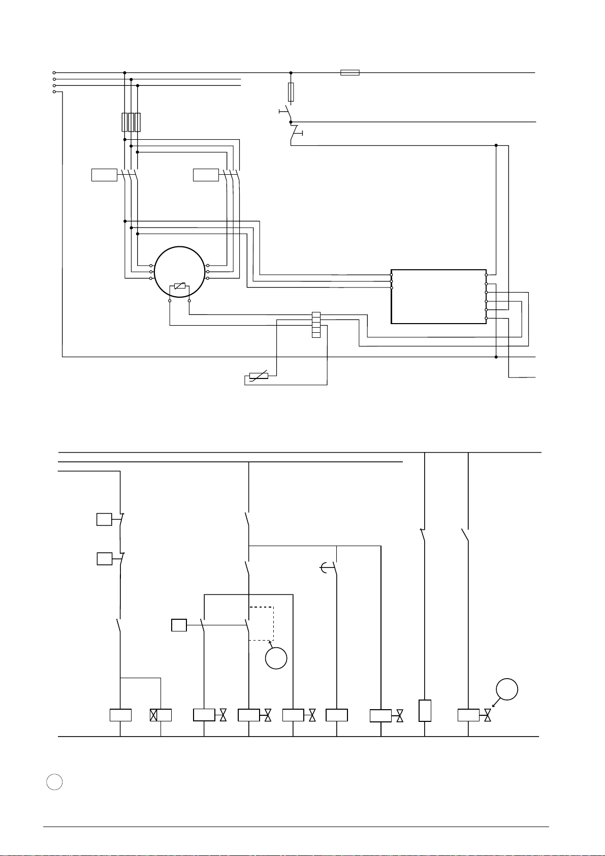
10.16 Schemi elettrici - Wiring diagrams - Schaltschemen
L1
L2
L3
N
F1
F2
L1.1
F3
TR1
*
Y (9)
X (8)
Z (7)
A
3
TR2
M
M
~
B
* rispettare la sequenza di collegamento TR1 - YXZ e TR2 - WVU
comply with the wiring sequence TR1 - YXZ and TR2 - WVU
W (3)
V (2)
U (1)
I
MR
L1.2
*
HT
CB
L1
L2
L3
INT69FRY
1
2
3
4
5
L
N
1
2
11
14
N
L1.3
FTEC11-01
L1.1
L1.2
L1.3
LP
HP
TS
TR1
CC
DR2
V2
TR1
TR2
V1
ECO
DR2
V3
TR2
V6
TR1
CH
TR2
ECO
V5
ECO solo con economizzatore
only with economizer
nur mit Economizer
42
Page 43

10.17 Legenda - Legend - Legende
CB morsettiera del compressore electric board of the compressor Klemmbrett des Verdichters
CC attuatore del controllo di capacità capacity control actuator Leistungsregelungsaktuator
CH riscaldatore olio oil heater Ölheizung
DR2 ritardatore per avviamento PWS (1 ÷ 2 sec.) time delay relay on PWS (1 ÷ 2 sec.) Verzögerungsrelais für PWS (1 ÷ 2 Sek.)
F1 fusibili circuito secondario control circuit fuse Sicherungen Steuerstromkreis
F2 fusibili circuito secondario control circuit fuse Sicherungen Steuerstromkreis
F3 fusibili compressore compressor fuses Sicherungen Verdichter
HP pressostato di alta pressione high pressure switch Hochdruckschalter
HT sensore max. temperatura di compressione max discharge temperature sensor Fühler Überhitzungsschutz
I interruttore principale ON / OFF ON / OFF switch EIN/AUS Schalter
LP pressostato di bassa pressione low pressure switch Niederdruckschalter
M motore elettrico electric motor Elektromotor
MR reinserzione manuale fault reset Störungs-Rückstellung
TR1 1° teleruttore per avviamento PWS 1st PWS start contactor Erster PWS Schütz
TR2 2° teleruttore per avviamento PWS 2nd PWS start contactor Zweiter PWS Schütz
TS termostato di sicurezza safety thermostat Sicherheitsthermostat
V1 controllo di capacità 50% 50% capacity control solenoid valve Magnetventil 50% Leistungsregelung
V2 controllo di capacità 75% 75% capacity control solenoid valve Magnetventil 75% Leistungsregelung
V3 valvola elettromagnetica linea del liquido liquid line solenoid valve Magnetventil Flüssigkeitsleitung
V5 valvola elettromagnetica dell’economizzatore solenoid valve on economizer Magnetventil am Economizer
V6 valvola elettromagnetica iniezione liquido liquid injection solenoid valve Magnetventil Flüssigkeitseinspritzung
FTEC11-01
solo per compressori: only for compressors: nur für Verdichter:
C-TSH8-70 240 Y C-TSH8-70 240 Y C-TSH8-70 240 Y
C-TSH8-80 240 Y C-TSH8-80 240 Y C-TSH8-80 240 Y
C-TSH8-80 270 Y C-TSH8-80 270 Y C-TSH8-80 270 Y
C-TSH8-90 270 Y C-TSH8-90 270 Y C-TSH8-90 270 Y
C-TSH8-90 300 Y C-TSH8-90 300 Y C-TSH8-90 300 Y
C-TSH8-100 300 Y C-TSH8-100 300 Y C-TSH8-100 300 Y
C-TSH8-100 360 Y C-TSH8-100 360 Y C-TSH8-100 360 Y
C-TSH8-120 360 Y C-TSH8-120 360 Y C-TSH8-120 360 Y
43
Page 44
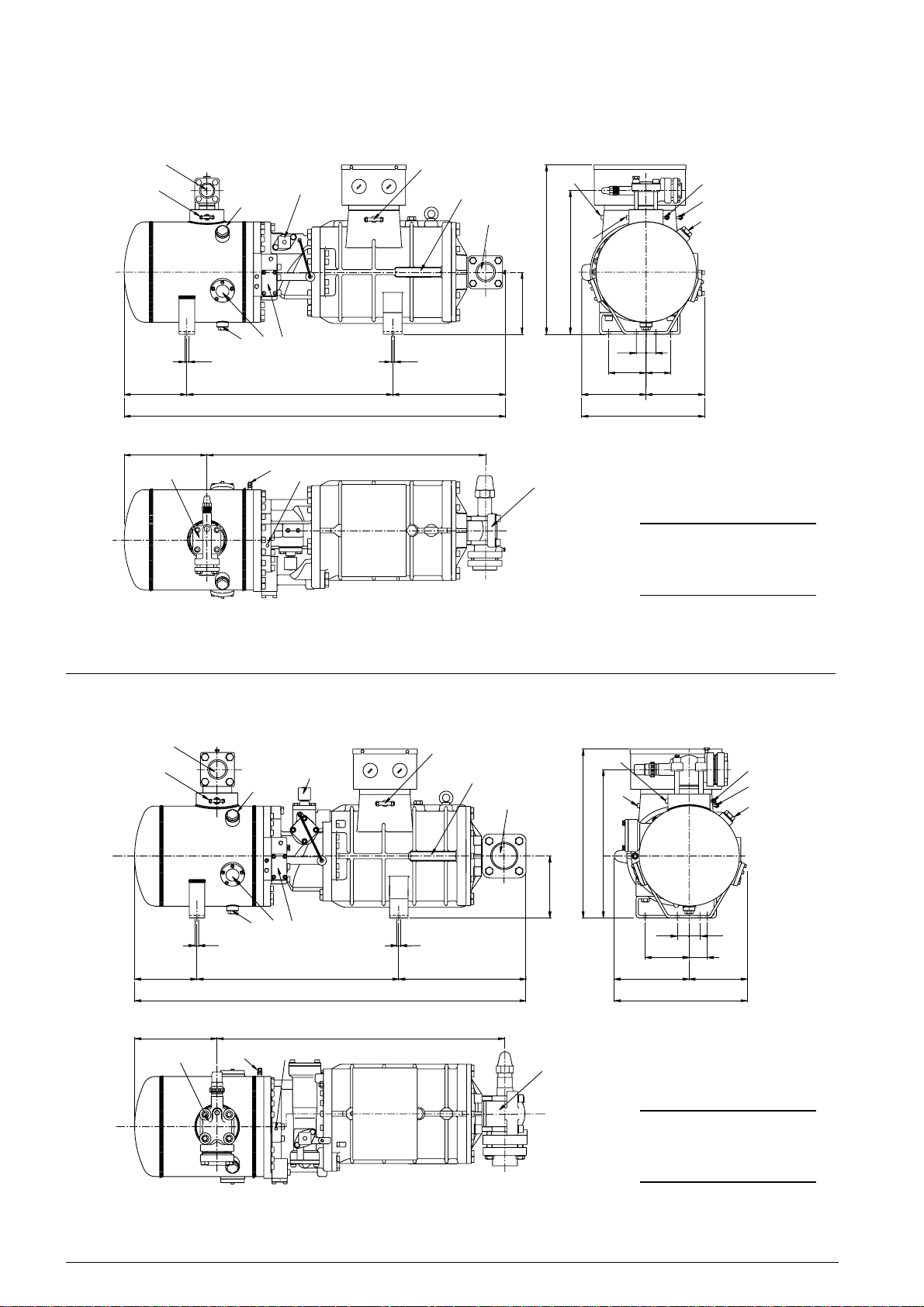
10.18 Dimensioni di ingombro - Dimensional drawings - Mass Zeichnungen
DV
7
205
267
DV
Ø 17
8
3
6
4
2
661 368
1234
898
9
5
Ø 17
1
NP
SV
200
517
10
463
7
1
8
11
45
45
120
80
198
187
385
C-TSH8-30 120 Y
SV
C-TSH8-40 120 Y
C-TSH8-40 150 Y
C-TSH8-50 150 Y
SV DV
ØØ ØØ
"mm "mm
DV
7
202
DV
2 1/8 54.0 1 5/8 42.0
1
8
9
6
423
Ø 17Ø 17
654
1267
931267
5
NP
SV
200
411
1
546
10
480
7
11
45
140
60
242
427
1
8
45
185
C-TSH8-50 186 Y
C-TSH8-60 186 Y
FTEC11-01
C-TSH8-60 210 Y
C-TSH8-70 210 Y
SV DV
44
ØØ ØØ
"mm "mm
3 1/8 80.0 2 1/8 54.0
Page 45
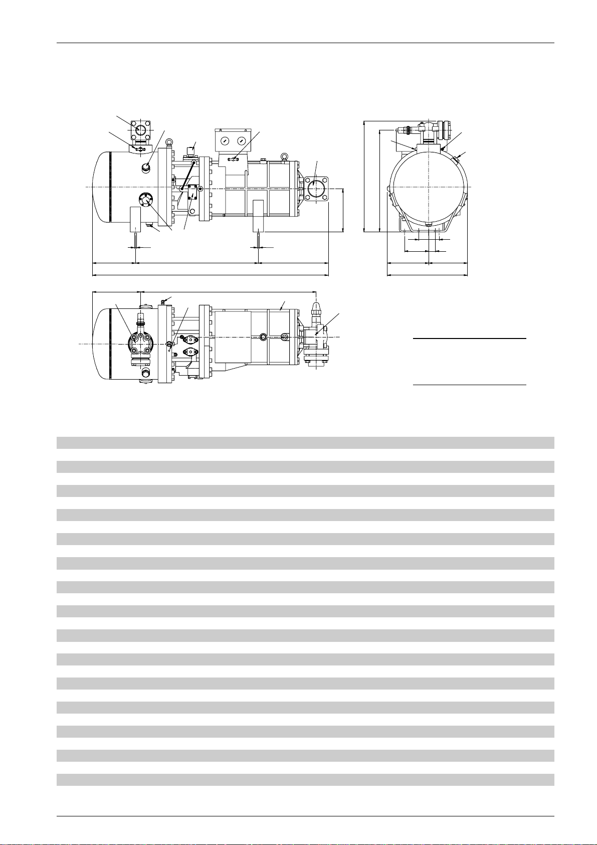
DV
7
8
6
1
SV
250
650
11
8
586
FTEC11-01
Ø 17
256 710
286
DV
4723
9
5
1371
1015
Ø 17
405
NP
70
140
240
SV
70
60
225
465
C-TSH8-70 240 Y
C-TSH8-80 240 Y
C-TSH8-80 270 Y
C-TSH8-90 270 Y
SV DV
ØØ ØØ
"mm "mm
3 1/8 80.0 2 1/8 54.0
1 attacco di bassa pressione low pressure connection Saugseiteanschluß 1/4" SAE
2 spia livello olio oil level sight glass Ölschauglas
3 scarico olio oil drain Ölablaß 3/8" SAE
4 attacchi per raffreddatore olio esterno connections for remote oil cooler Ölkühleranschlüsse
5 sensore max. temp. compressione maximum discharge temperature sensor Druckgasfühler
6 valvola controllo di capacità capacity control valve Leistungsregelungventil
7 attacco di alta pressione high pressure connection Druckseiteanschluß 1/4" SAE
8 attacco di servizio service connection Betriebsanschluß 3/4" NPT
9 attacco iniezione di liquido/economizzatore liquid injection/economizer connection Economizer/Flüssigkeitseinspritzungsanschluß 3/8" SAE
per compressori: for compressors: für Verdichter:
C-TSH8-30-120 Y C-TSH8-40-120 Y C-TSH8-40-150 Y C-TSH8-50-150 Y C-TSH8-50-186 Y C-TSH8-60-186 Y C-TSH8-60-210 Y C-TSH8-70-210 Y
9 attacco iniezione di liquido/economizzatore liquid injection/economizer connection Economizer/Flüssigkeitseinspritzungsanschluß 1/2" SAE
per compressori: for compressors: für Verdichter:
C-TSH8-70-240 Y C-TSH8-80-240 Y C-TSH8-80-270 Y C-TSH8-90-270 Y
10 tappo per attacco di bassa pressione plug for low pressure connection Stopfen für Saugseiteanschluß 1/8" NPT
11 tappo per attacco di alta pressione plug for high pressure connection Stopfen für Druckseiteanschluß 1/8" NPT
DV rubinetto di compressione discharge valve Druckventil
NP targhetta name plate Verdichtertypschild
SV rubinetto di aspirazione suction valve Saugventil
45
Page 46
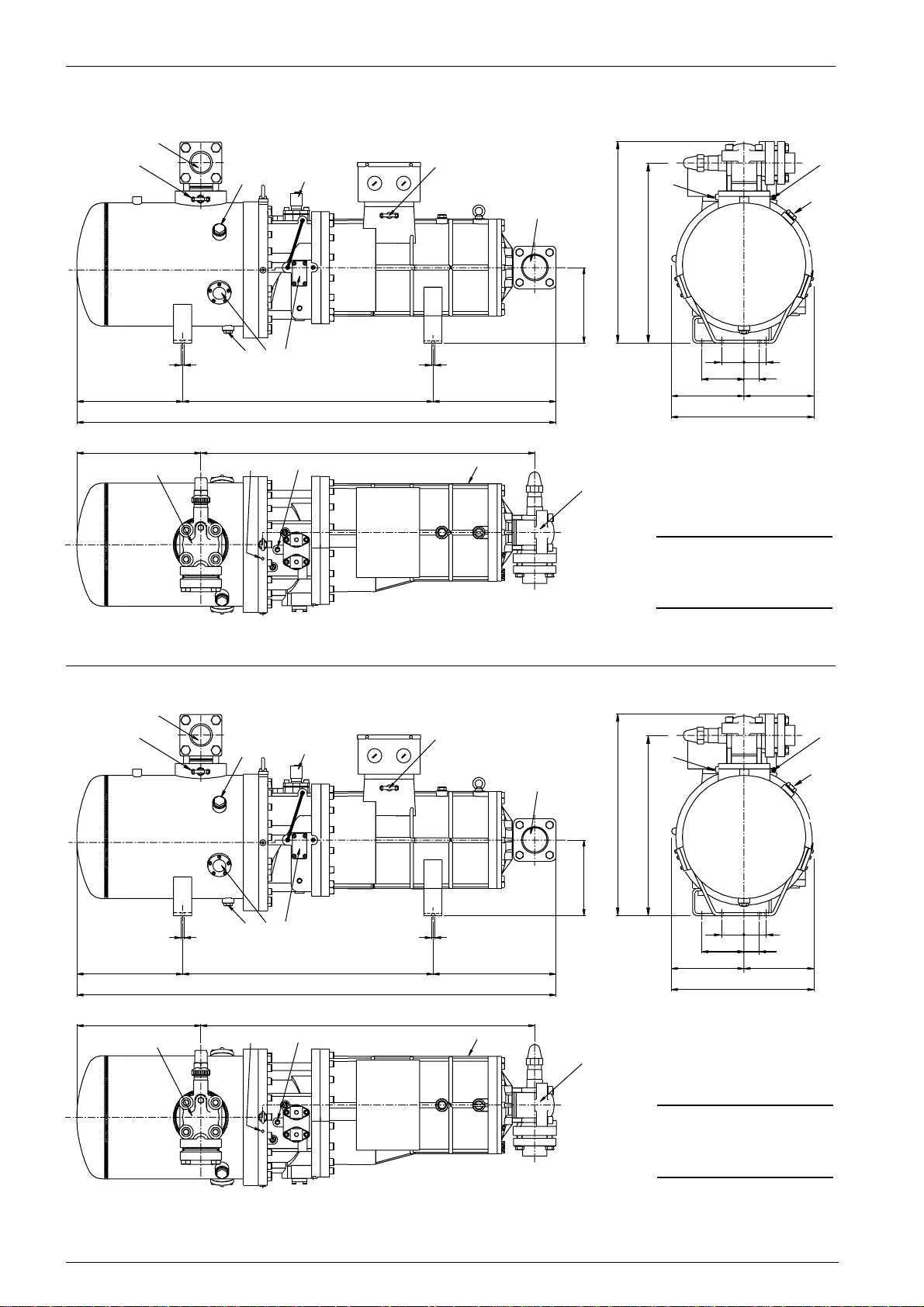
DV
7
8
6
1
SV
250
665
11
604
7
8
354
409
7
DV
DV
Ø 17
3
42
827
1584
1102
5
9
Ø 17
NP
403
140
240 230
SV
7070
60
470
C-TSH8-90 300 Y
C-TSH8-100 300 Y
SV DV
ØØ ØØ
"mm "mm
3 1/8 80.0 2 5/8 67.0
8
6
1
11
SV
7
8
FTEC11-01
354
409
DV
Ø 17
665
604
250
423
827
1584
1102
5
9
Ø 17
NP
403
140
240 230
SV
7070
60
470
C-TSH8-100 360 Y
C-TSH8-120 360 Y
SV DV
ØØ ØØ
"mm "mm
3 1/8 80.0 2 5/8 67.0
46
Page 47

1 attacco di bassa pressione low pressure connection Saugseiteanschluß 1/4" SAE
2 spia livello olio oil level sight glass Ölschauglas
3 scarico olio oil drain Ölablaß 3/8" SAE
4 attacchi per raffreddatore olio esterno connections for remote oil cooler Ölkühleranschlüsse
5 sensore max. temp. compressione maximum discharge temperature sensor Druckgasfühler
6 valvola controllo di capacità capacity control valve Leistungsregelungventil
7 attacco di alta pressione high pressure connection Druckseiteanschluß 1/4" SAE
8 attacco di servizio service connection Betriebsanschluß 3/4" NPT
9 attacco iniezione di liquido/economizzatore liquid injection/economizer connection Economizer/Flüssigkeitseinspritzungsanschluß 5/8" SAE
10 tappo per attacco di bassa pressione plug for low pressure connection Stopfen für Saugseiteanschluß 1/8" NPT
11 tappo per attacco di alta pressione plug for high pressure connection Stopfen für Druckseiteanschluß 1/8" NPT
DV rubinetto di compressione discharge valve Druckventil
NP targhetta name plate Verdichtertypschild
SV rubinetto di aspirazione suction valve Saugventil
FTEC11-01
47
Page 48

Page 49

Page 50

Page 51

Page 52

FRASCOLD spa
Headquarters
Via Barbara Melzi 105
I-20027 Rescaldina (MI)
phone +39-0331-7422.01
e-mail: [email protected]
ITALY
fax +39-0331-576102
http://www.frascold.it
Branches
FRASCOLD Asia
10 Jalan Hikayat
Singapore 769855
SINGAPORE
phone +65-6851-7318
fax +65-6851-7055
mobile +65-967-71827
e-mail: [email protected]
 Loading...