

Franzis Do-it-yourself User Manual
Do-it-yourself
VHF Retro Radio
Dear Customers,
This product was developed in compliance with the applicable European directives
and therefore carries the CE mark. Its authorized use is described in the instructions
enclosed with it. In the event of non-conforming use or modification of the product,
you will be solely responsible for complying with the applicable regulations. You should therefore
take care to assemble the circuits as described in the instructions. The product may only be passed
on along with the instruction and this note.
Waste electrical products should not be disposed of with household waste. Please recycle where facilities exist. Check with your local authority or retailer for recycling advice.
© 2014 Franzis Verlag GmbH, Richard-Reitzner-Allee 2, 85540 Haar, Germany
All circuits and programs depicted in this book are developed and tested with utmost care.
Nonetheless, it is not possible to rule out all errors in the book or in the software. Publisher and author
are only liable in case of intent or gross negligence according to legal regulation. Beyond that, publisher and author are only liable according to the law on product liability concerning hazards to life,
body, and health and the culpable violation of essential contractual obligations. The damage claim
for the violation of essential contractual obligations is limited to the contract-specific, predictable
damage, unless in cases of mandatory liability according to the law on product liability.
All rights reserved, including those of reprinting, reproduction and storage in electronical media. No
part may be reproduced and distributed on paper, on storage media, or in the Internet, especially as
PDF, without the publisher‘s prior written permission. Any attempt may be prosecuted. Hardware and
software product names, company names, and company logos mentioned in this book are generally
registered trademarks and have to be considered as such. For product names, the publisher uses
mainly the spelling of the manufacturer.
Translation and DTP: G&U Language & Publishing Services GmbH
Author: Burkhard Kainka
Art & Design Cover: www.ideehoch2.de
ISBN 978-3-645-65228-5
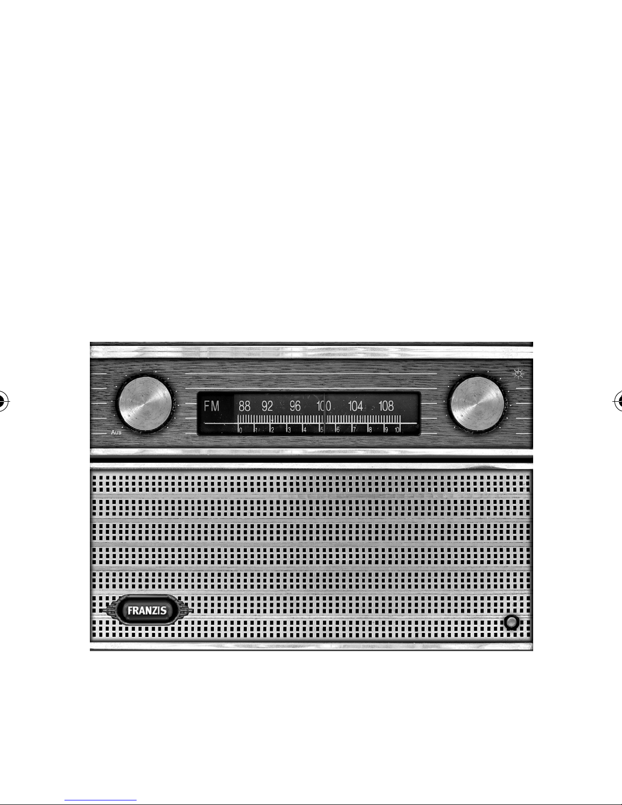
The VHF Retro Radio
This modern VHF radio in vintage style receives FM stations
in the 87.5 MHz to 108 MHz band with good reception performance. You will mainly hear the powerful local stations in
high sound quality. However, the sensitivity of the receiver also
allows you to listen to remote stations at times.
3

Large-scale introduction of VHF broadcasting began only after
1945. Initially there were still many radios that were able to receive only the AM ranges – long wave, medium wave and short
wave. Many devices, however, could be upgraded with VHF retrofit kits. During the 1950s the tube superhet with VHF range
became widely accepted.
This radio looks very much like a typical portable radio of the
1960s. The invention of the transistor allowed the construction of radios that consumed less power than valve receivers
and therefore could be operated with batteries. Apart from this,
they technically still resembled the older tube radios.
Thanks to the highly integrated receiver IC TDA7088 building
your own VHF radio has become so easy that anybody will be
successful in soldering this radio together. The single-ended
low frequency amplifier functions pretty much like the historical tube radio. Your nostalgic radio works with a dual-stage
transistor amplifier with medium volume at low battery voltage. Now you only need two 1.5-V alkaline batteries for up to
100 hours of radio reception. With your DIY-radio listening to
the radio will become even more fun. Enjoy the diversity of the
VHF stations.
4
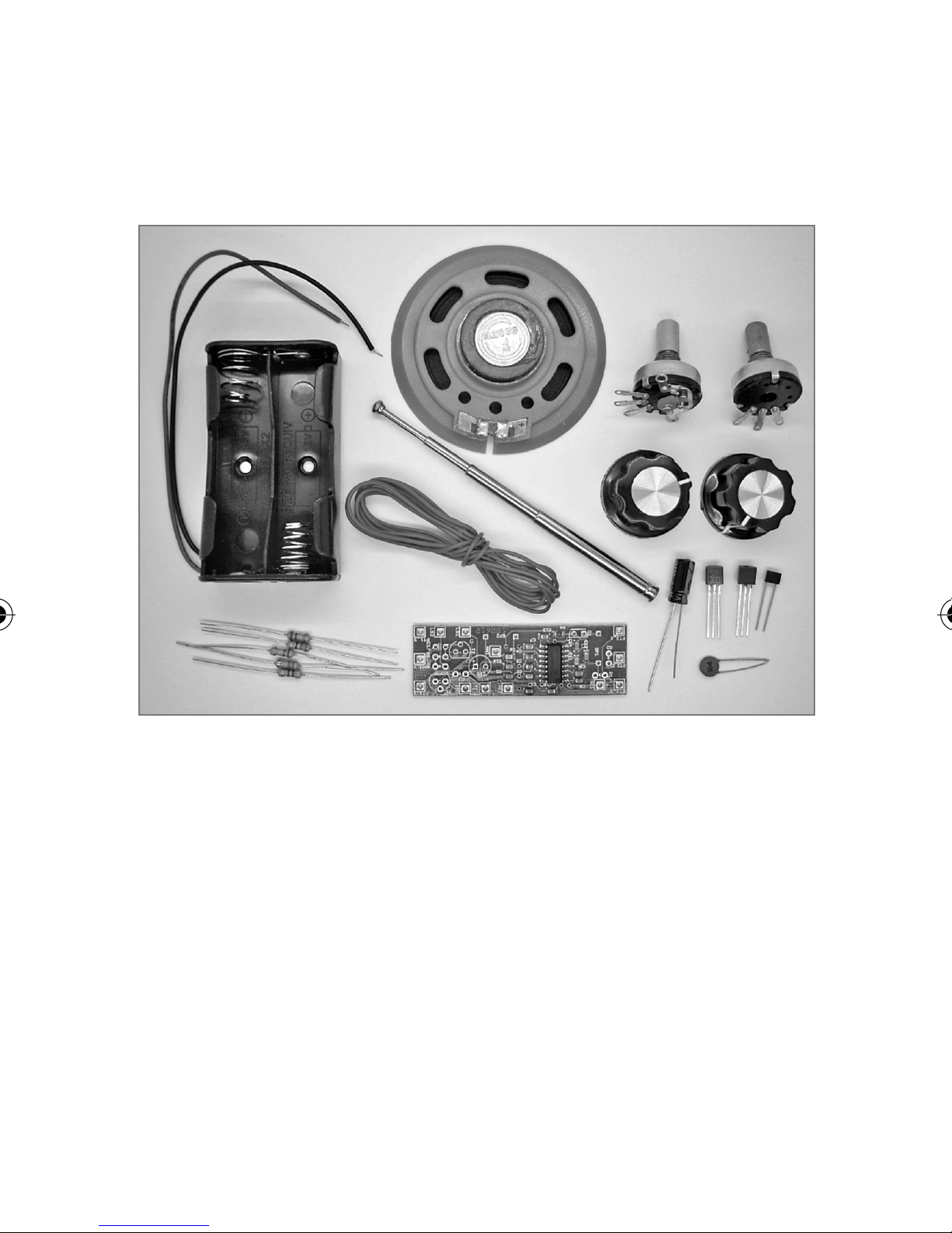
Components
pre-assembled PCB with TDA7088
•
rod antenna
•
speakers 8 Ω, 0.5 W
•
volume control 22 kΩ with switch
•
tuning control 22 kΩ
•
insulated wire
•
battery compartment with connection wires
•
T1 PNP transistor BC557B
•
T2 NPN transistor BC547B
•
5

D1 varactor diode 1SV101
•
R1 4.7 kΩ (yellow, violet, red)
•
R2 220 kΩ (red, red, yellow)
•
R3 1 kΩ (brown, black, red)
•
R5 330 kΩ (orange, orange, yellow)
•
R6 33 Ω (orange, orange, black)
•
C15 electrolytic capacitor 100 µF
•
C17 100 µF ceramic (104)
•
Assembly of the control elements
The radio has two rotary controls – one for frequency and one
for volume. The three-port volume controller is equipped additionally with the two-port on/off switch. If you turn the axis
all the way to the left, the switch opens. Insert the volume controller into the left mounting hole. A small tab secures correct
insertion. Fix the controller with the ring nut and do not forget
the washer.
The second potentiometer with 22 k
tuning and is mounted on the right. The connections of both
potentiometers should face inwards so that the board can be installed between them later. Then screw both rotary knobs onto
the axes so that the end stops are aligned with the printed scales.
Ω is used for frequency
6
 Loading...