

Page 1

Rev. A September 2014
Section No: 4.1.32 Page 1 of 14
Prepared By: J. Gaspard
QHSE Integrated Procedure Manual Approved By: QHSE Committee
OPS-P-4.1.32 DDS Connectors Installation
1.0 Purpose
To standardize the method by which DDS Pin and Box Connectors are installed.
2.0 Scope
This procedure outlines the requirements for the installation of DDS Pin and Box Connectors.
3.0 Definitions
None
4.0 Responsibility
4.1 Departmental Supervisor
4.1.1 The Departmental Supervisor shall be responsible for delegating technicians to
install DDS Pin and Box Connectors such that they meet the requirements of
this procedure.
4.1.2 The Departmental Supervisor shall ensure that any technician selected to
perform activities covered by this procedure is properly trained.
4.2 Connector Running Technician
4.2.1 The Connector Running Technician is responsible for obtaining and bringing
the proper work instructions for the type and size of connector being run to the
job site.
4.2.2 The Connector Running Technician is responsible for completing Equipment
Fault Reports on all nonconforming situations encountered during the course of
running the connector string.
5.0 Procedure
5.1 Pre-installation Instructions
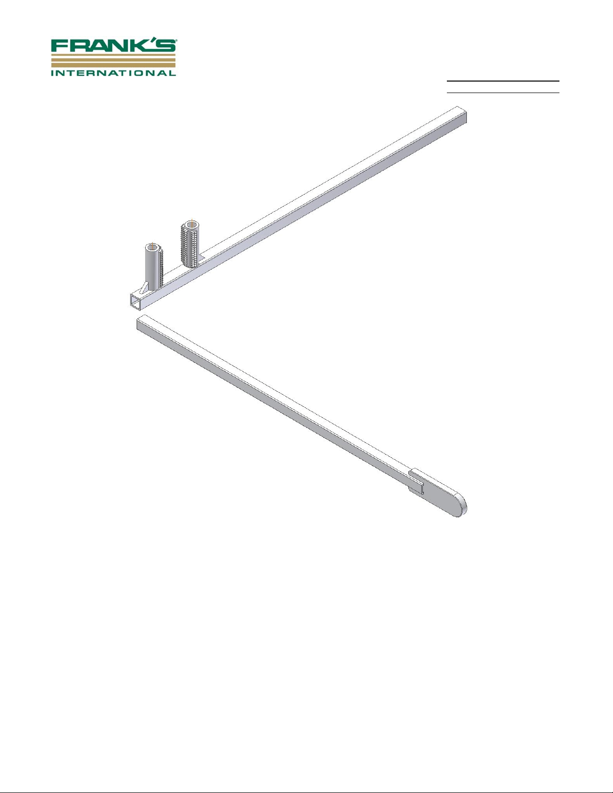
5.1.1 Verify that box protectors are tight by inserting DDS protector spade breaker
bar (part# SOG199905100) into slot on the protector or by using DDS protector
breaker bar (part# SOG199905081) and turn the protector in a clockwise
motion (refer to Figure 1 and pages 14 and 15, respectively). Ensure that the
protector is visually shouldered to the connector.
Document may be uncontrolled if printed, verify current approved revision before use.
Page 2
Rev. A September 2014
Section No: 4.1.32 Page 2 of 14
Prepared By: J. Gaspard
QHSE Integrated Procedure Manual Approved By: QHSE Committee
DDS Protector Breaker Bar
Part# SOG199905081
DDS Protector Spade Breaker Bar
Part# SOG199905100
Figure 1
5.1.2 Visually inspect the ID of the pipe to ensure that it is clean and free of debris.
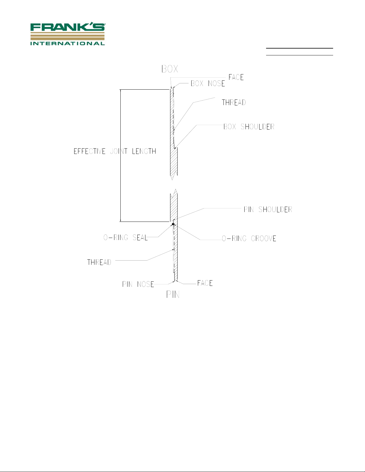
5.1.3 Tally pipe / connectors using locations as shown in Figure 2. Ensure that the
pipe is clearly identified and mark the effective joint length clearly on the pipe
surface.
NOTE: Ensure that the required pipe handling equipment is available.
Ensure that the correct spare parts running kit is available.
Document may be uncontrolled if printed, verify current approved revision before use.
Page 3
Rev. A September 2014
Section No: 4.1.32 Page 3 of 14
Prepared By: J. Gaspard
QHSE Integrated Procedure Manual Approved By: QHSE Committee
Figure 2
5.2 Installation Instructions - DDS Connectors
5.2.1 A single joint of pipe is presented to the rig floor and held in a horizontal
position using slings. Depending on the rig, it may also arrive on a skate. The
bottom of the pipe shall be 1-1/2 to 2 feet above the rig floor, and the end of
the pipe containing the lift shoulder shall be 2 to 3 feet from the well bore.
5.2.2 Verify that box protectors are tight by inserting DDS protector spade breaker
bar (part# SOG199905100) into slot on the protector or by using DDS protector
breaker bar (part# SOG199905081) and turn the protector in a clockwise
motion (refer to Figure 1 and pages 14 and 15, respectively). Ensure that the
protector is visually shouldered to the connector.
Document may be uncontrolled if printed, verify current approved revision before use.
Page 4
Rev. A September 2014
Section No: 4.1.32 Page 4 of 14
Prepared By: J. Gaspard
QHSE Integrated Procedure Manual Approved By: QHSE Committee
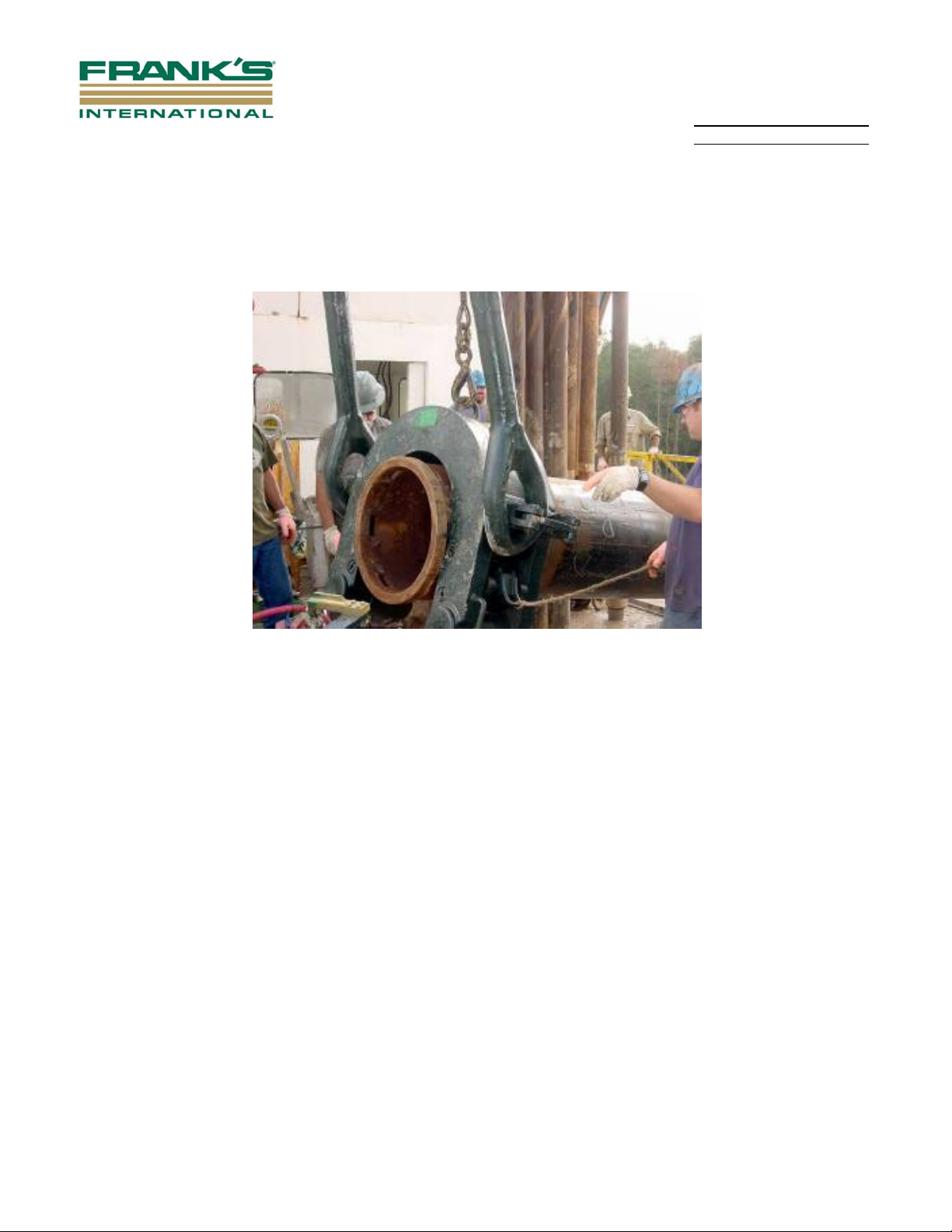
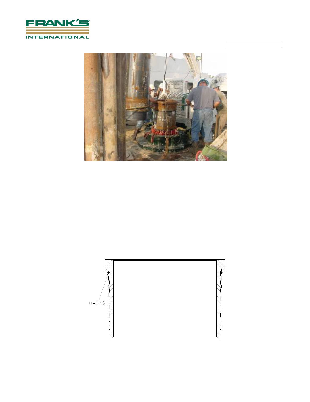
5.2.3 Attach an air winch line to the back of the elevator (refer to Figure 3). Once the
air winch line is attached, use it to pick up the back of the elevator. This will
rotate the elevator to a vertical position as well as position it above the end of
the pipe. Alternately, a top drive link tilt may be employed to push the bails out.
The elevator is then lowered onto the pipe and secured.
Figure 3
5.2.4 Remove the air winch line, pass it through the eye of the closest V-door post
and attach it to the post on the opposite side of the V-door. This catch line will
restrain the pipe from swinging when brought into a vertical position.
5.2.5 Clear all non-essential personnel from the rig floor.
5.2.6 Start lifting the elevator and pipe with slings still attached. Remove the sling
closest to the elevator first when it begins to show slack. Remove the second
sling when it too begins to show slack.
5.2.7 Elevate the pipe until the pin end of the joint clears the V-door with the air hoist
catch line restraining the pipe. Hold in place about 1 foot above the rig floor.
5.2.8 Pull a length of chain from the draw works, shackle the end of the chain to the
supplied Kevlar rope and hook with a swivel (part # 60191).
5.2.9 Insert the steel hook (1" to 1-1/4" part# SOG199905095 refer to page 16, or
1-1/2" to 2" part# SOG199905097 refer to page 17) into one of the rectangular
slots in the bottom of the pin protector and wrap the rope around the protector,
not less than two full turns.
Document may be uncontrolled if printed, verify current approved revision before use.
Page 5
Rev. A September 2014
Section No: 4.1.32 Page 5 of 14
Prepared By: J. Gaspard
QHSE Integrated Procedure Manual Approved By: QHSE Committee
5.2.10 Pull slowly on the chain with the draw works to breakout the pin protector and
let it fall freely to the rig floor. Keep all personnel clear of the drop zone in order
to prevent the possibility of foot injuries.
5.2.11 Elevate the pipe and feed out the catch line so that the pipe joint becomes
nearly vertical, but not over the well bore, just slightly in front of the spider.
5.2.12 See Section 5.4 for repair procedure if indications such as burrs or light galling
are observed.
5.2.13 The box protector must be removed when a joint is being supported by the
spider. Pull a length of chain from the draw works and shackle the end of the
chain to the supplied Kevlar rope and hook using a swivel.
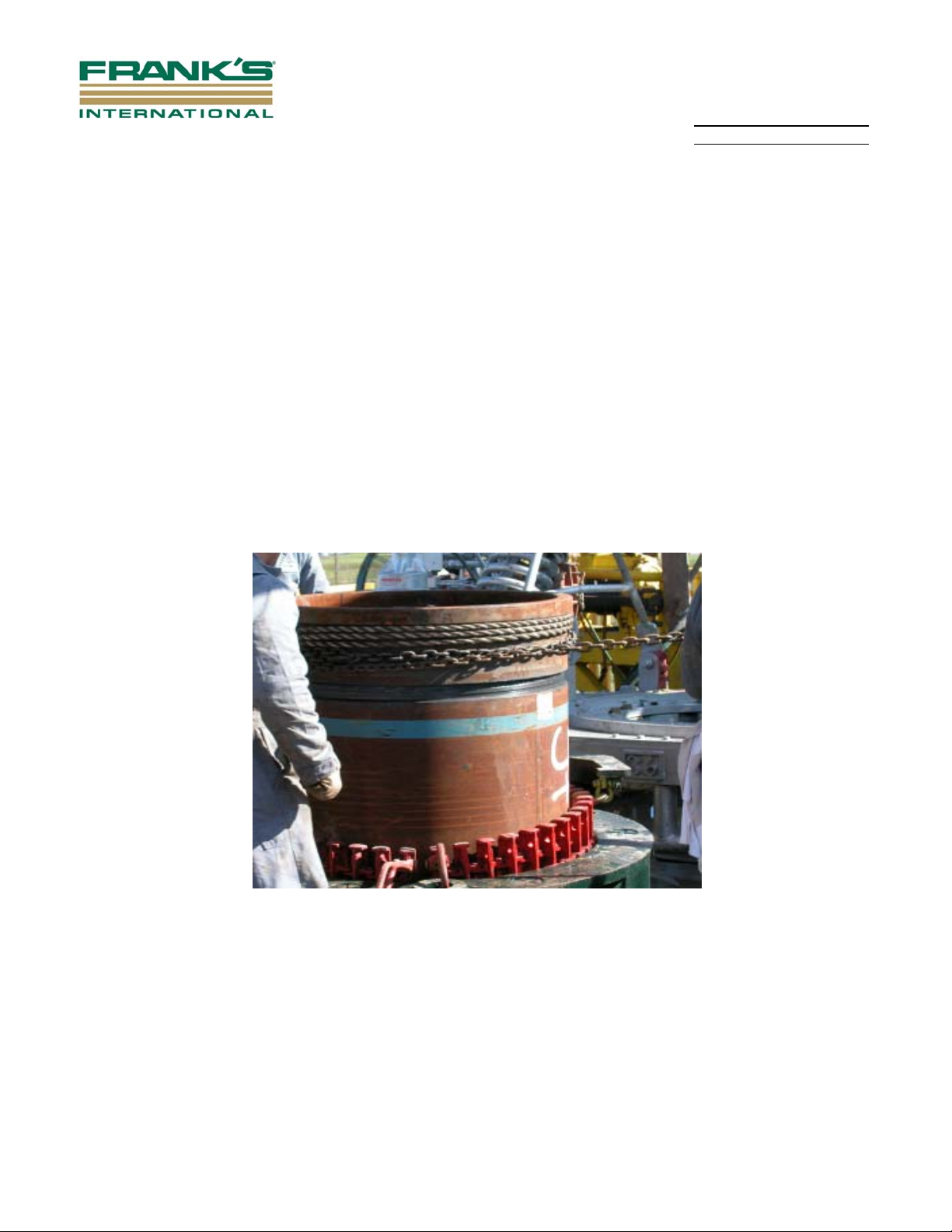
5.2.14 Insert the steel hook into one of the rectangular slots in the top of the box
protector and wrap the rope around the protector, not less than three full turns
(refer to Figure 4).
Figure 4
NOTE: Completely unscrewing the box protector with draw works will
damage the connector.
5.2.15 Pull slowly on the chain with the draw works to breakout the box protector, until
3 threads on the box protector are visible. Use the supplied DDS protector
spade breaker bar (part# SOG199905100) to finish backing out the protector
(refer to Figure 5).
Document may be uncontrolled if printed, verify current approved revision before use.
Page 6
Rev. A September 2014
Section No: 4.1.32 Page 6 of 14
Prepared By: J. Gaspard
QHSE Integrated Procedure Manual Approved By: QHSE Committee
Figure 5
5.2.16 Lift the protector clear of the box with the supplied three part protector sling
(part# 82041, refer to page 13) and an air hoist and lower it down to the rig floor
and stab it into a pin protector. Make-up by hand and send down to the V-door.
5.2.17 See Section 5.4 for repair procedure if indications such as burrs or light galling
are observed.
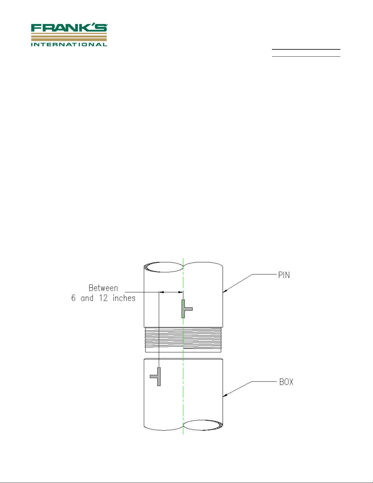
5.2.18 Install the o-ring into the uppermost groove of the pin, about 1/2" below the
shoulder (refer to Figure 6). Refer to Table 1 for proper o-ring on each
corresponding connector size.
Figure 6
Document may be uncontrolled if printed, verify current approved revision before use.
Page 7
Rev. A September 2014
Section No: 4.1.32 Page 7 of 14
Prepared By: J. Gaspard
QHSE Integrated Procedure Manual Approved By: QHSE Committee
5.2.19 Once in this position, the pipe will either be lowered until the elevator is 3 feet
above the spider, or the pipe will be stabbed into the rest of the string of pipe
and make-up using a tong.
5.2.19.1 If the joint of pipe just lifted is the first joint, proceed to step 5.2.27.
5.2.19.2 If it is an intermediate or the last joint of pipe in the string, proceed to
step 5.2.20.
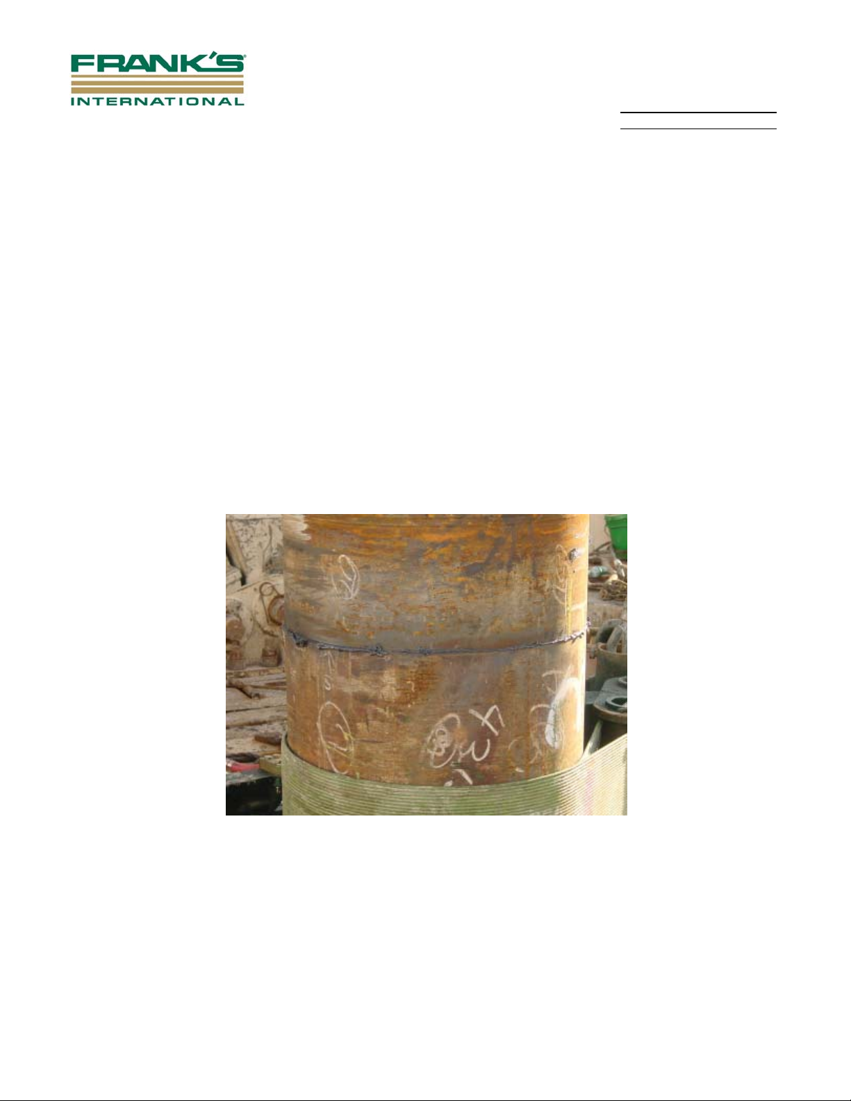
5.2.20 The starting threads shall be marked prior to stabbing. To mark the starting
threads, locate the start of thread on the connector and mark it with a line
along the axis of the pipe then draw a line around the circumference of the
pipe following the direction of the thread. To stab the connector, the starting
thread on the pin connector shall be rotated approximately 6" to 12"
counterclockwise from the starting thread on the box connector. Once the
connectors are lined up, the joint can then be lowered slowly and stabbed into
the joint that is being supported by the spider (refer to Figure 7). During the
stabbing operation, if the joint gets hung up on the threads, or if the driller
drops Pin into Box with any impact, the DDS technician shall have the joint
lifted and go through a visual inspection on the threads. Threads should be
repaired if necessary.
PROPER STABBING ORIENTATION
Figure 7
Document may be uncontrolled if printed, verify current approved revision before use.
Page 8
Rev. A September 2014
Section No: 4.1.32 Page 8 of 14
Prepared By: J. Gaspard
QHSE Integrated Procedure Manual Approved By: QHSE Committee
5.2.21 Once the connectors are stabbed together, the back up tong is attached to the
pipe being supported by the spider.
5.2.22 Once the backup is attached, the elevator is lowered approximately 2 feet to
allow the free rotation of the pipe during make-up.
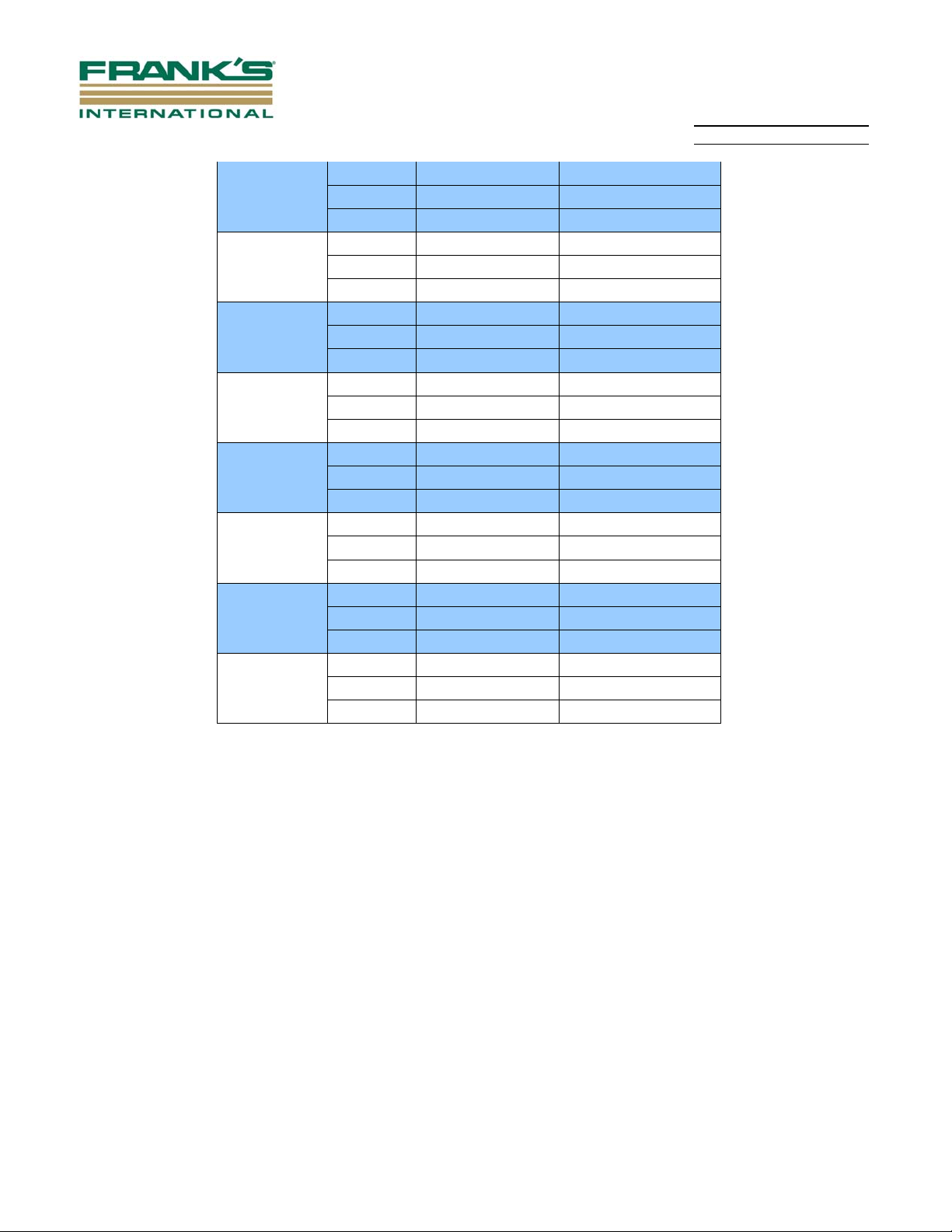
5.2.23 The connection is then made up using a manual or hydraulic tong to the
proper torque specification (refer to Table 2). Begin making up connector
using the hydraulic tong in the “low gear” setting, for a minimum of 2
rotations. Then shift the tong to the “high gear” setting, and proceed with
making up the joint slowly.
NOTE: FCC Special Operations Group Engineering Department must
approve any request to deviate from the torques listed in Table 2.
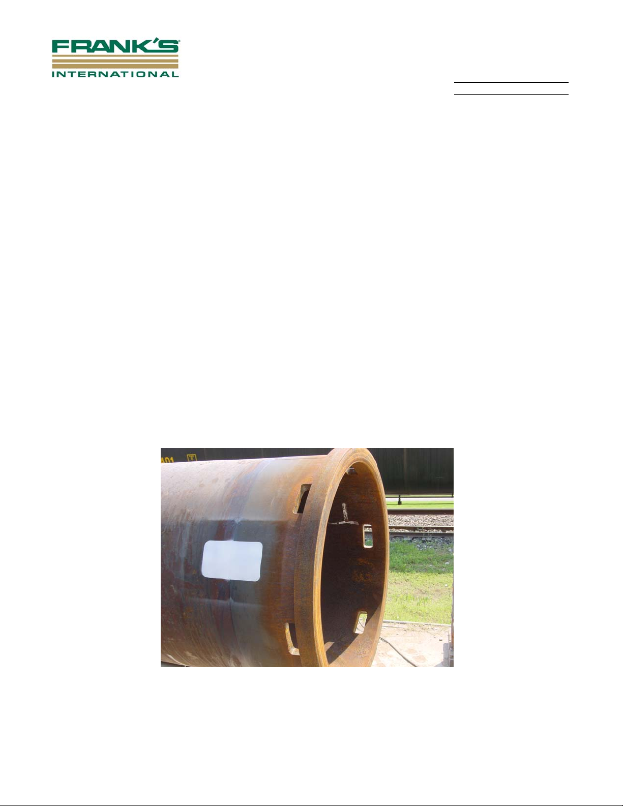
5.2.24 After make-up, visually inspect the connection to ensure that it has shouldered
properly (refer to Figure 8).
Figure 8
5.2.25 If hammering operation is necessary at this point, proceed to step 5.2.30. If NO
HAMMERING IS NECESSARY at this point, then proceed to step 5.2.26.
5.2.26 After the connection is inspected for proper make-up, remove make-up and
backup tongs.
5.2.27 Lift string with elevator and unset the slips on the spider and lower the string
until the elevator is approximately 3 feet above the spider.
Document may be uncontrolled if printed, verify current approved revision before use.
Page 9
Rev. A September 2014
Section No: 4.1.32 Page 9 of 14
Prepared By: J. Gaspard
QHSE Integrated Procedure Manual Approved By: QHSE Committee
5.2.28 Set the slips in the spider.
5.2.29 Unlatch the elevator. Pull the elevator away from the pipe until the elevator
body is clear of the load shoulder using air hoist or link tilt system and return to
step number 5.2.1 to repeat the process.
5.2.30 Visually inspect the box protector at the top of the string to verify that the
painted-on white box across the seam has not been separated or misaligned
BEFORE the hammer operation begins (an undisturbed DDS box protector
shall resemble that in Figure 9).
5.2.31 After the protector has been inspected and found to be fully shouldered,
proceed with a safe hammering operation until proper blow count is reached.
NOTE: Once 150 BPF is reached, inspect hammer and adapter guide bolts,
hammer block, rigging equipment, Padeyes, floating bell, and lead for
damage.
After 200 BPF is reached, contact Hammer Department Manager for
further instructions.
5.2.32 Safely remove hammer and corresponding equipment from the string and
return now to step number 5.2.1 to repeat the process.
Figure 9
5.3 General Notes - DDS Connector
This is a general procedure. Changes can be made for special applications. Contact
FCC Special Operations Group Engineering Department for approval of any changes.
Document may be uncontrolled if printed, verify current approved revision before use.
Page 10
Rev. A September 2014
Section No: 4.1.32 Page 10 of 14
Prepared By: J. Gaspard
QHSE Integrated Procedure Manual Approved By: QHSE Committee
5.4 Repair of Threads - DDS Connectors
If indications such as burrs or light galling are observed, the connector threads shall
be dressed using the following procedure:
5.4.1 Completely wipe the connector clean of all AP-5 Jet Lube.
5.4.2 Using the supplied air grinder and carbide bit (see Section 5.5 Parts List -
Running Box), grind down the burr or the area of galling completely.
5.4.3 Once the indications are removed, remove the carbide bit and install a 3"
flapper wheel (see Section 5.5 Parts List - Running Box), smooth out the areas
that were previously grinded on.
5.4.4 Completely wipe the connector clean of all shavings and reapply a light coat of
AP-5 Jet Lube using the supplied paint brushes.
NOTES: All Indications on the connector shall be evaluated by a trained DDS
Technician supplied by Frank’s. The procedure for removing
indications shall be performed by a trained DDS Technician supplied
by Frank’s.
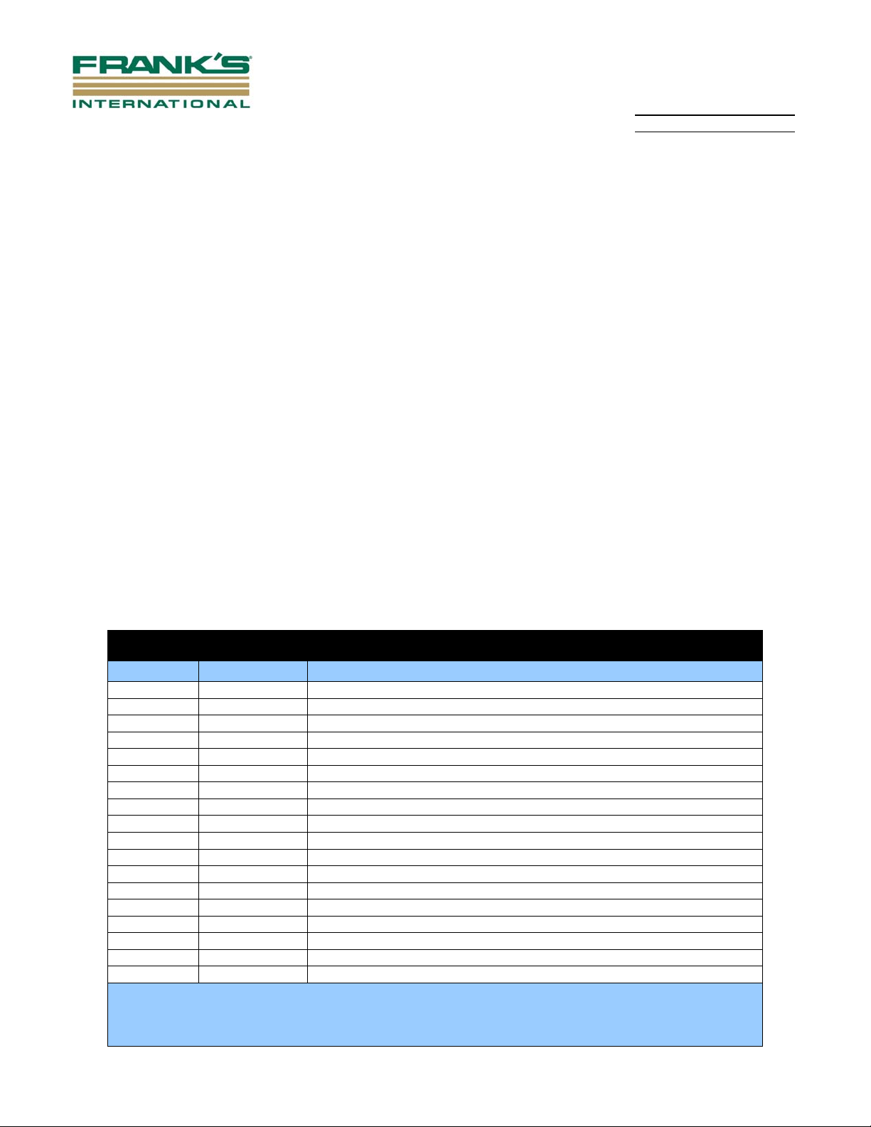
5.5 Parts List - Running Box
DDS RUNNING BOX CONTENTS
Item No. Qty. Req. Description
1 2 DDS Protector Breaker Bar, Part # SOG199905081
2 2 DDS Protector Spade Breaker Bar, Part # SOG199905100
3 1 1" to 1-1/4" Kevlar Rope Assembly, Part # SOG199905095
4 1 1-1/2" to 2" Kevlar Rope Assembly, Part # SOG199905097
5 2 7/8" Crosby Bolt-type Anchor Shackle, Part # 60181
6 2 1/2" Crosby Bolt-type Anchor Shackle, Part # 60067
7 1 DDS Protector Handling Hook 1" to 1-1/4", Part # SOG199905013
8 1 DDS Protector Handling Hook 1-1/2" to 2", Part # SOG199905056
9 Job Specific* O-Ring, BUNA N-90-A, Cold Bond Joint Loctite 404**
10 1 3 Part Lifting Chain, Part # 82041
11 1 Air Grinder
12 1 Flashlight
13 2 Carbide Grinding Bit # 7N132ADC, Part # SN-4
14 2 Carbide Grinding Bit # 7B132BDC, Part # SB-5
15 4 3" Flapper Wheels, Part # 08834149837
16 1 Box of “Markal” Paint Markers, LA-CO Industries, Inc., Part# 96820
17 1 Pail of AP-5 Jet Lube
18 4 Paint Brushes
* NOTE: For Required Qty of O-Rings, Double the Qty of “PIN x BOX Joints”. For Example, if Running
10 Joints of Pipe, the Required Qty of O-Rings is 20.
**NOTE: For Proper Size of O-Ring, Reference Table 1 for Connector Size and Corresponding O-Ring.
Document may be uncontrolled if printed, verify current approved revision before use.
Page 11

Rev. A September 2014
Section No: 4.1.32 Page 11 of 14
Prepared By: J. Gaspard
QHSE Integrated Procedure Manual Approved By: QHSE Committee
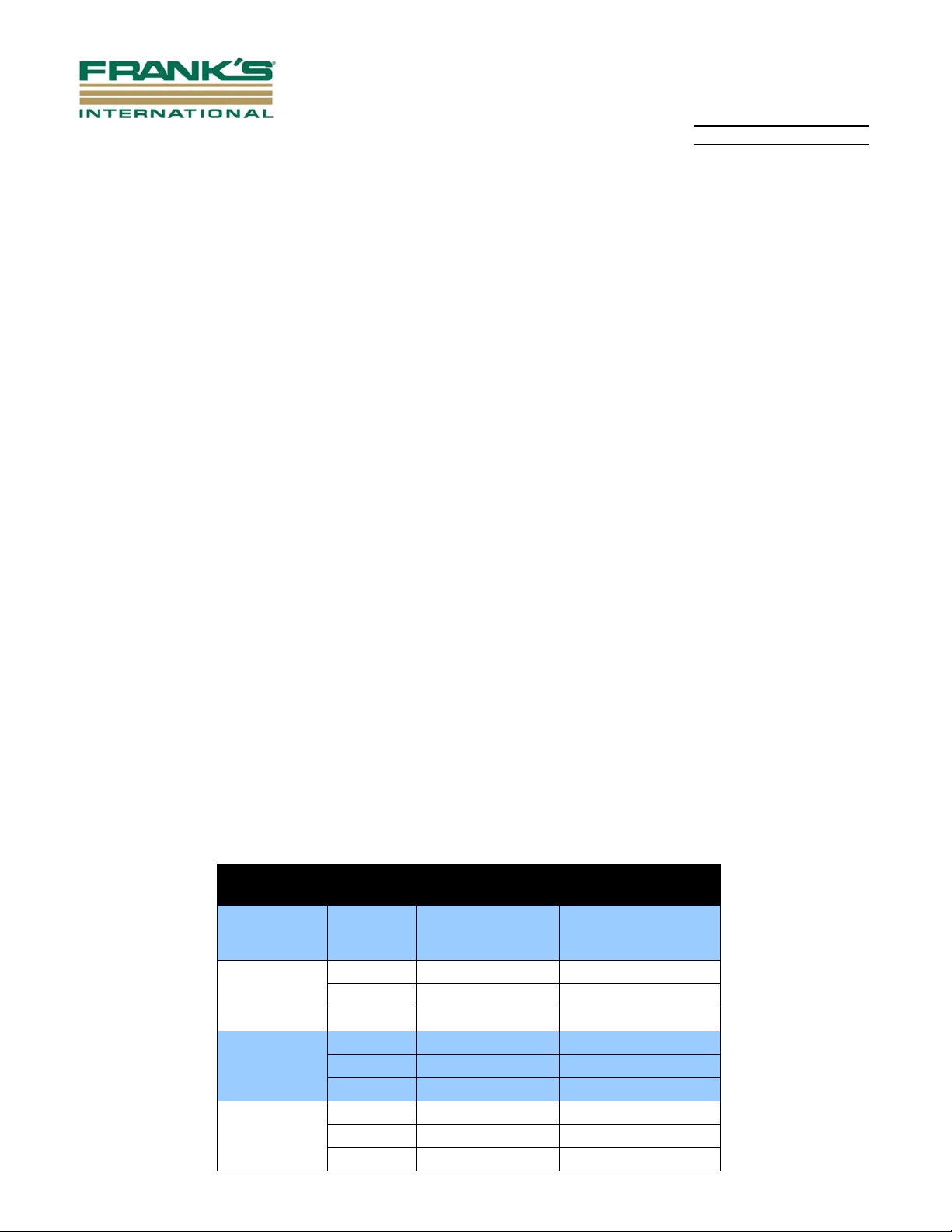
O-ring Size Chart
Description Order # Fcc Part #
16" x 3/4"thru 5/8" (K-Series) 13.164 I.D x.125 CS N90 ~ C/L = 41.750 46524
20" x 13/16"thru 5/8" (K-Series) 16.593 I.D x .118 CS N90 ~ C/L = 52.500 46483
22" x 1.0" x 5/8" (K-Series) 18.314 I.D x .118 CS N90 ~ C/L = 57.906 46499
24" x 3/4" (K-Series) 19.928 I.D x .126 CS N90 ~ C/L = 63.000 46602
24" x 1.0" x 1.0" 19.896 I.D x .157 CS N90 ~ C/L = 63.000 46369
24" x 1.5" x 1.5" 19.844 I.D x .210 CS N90 ~ C/L = 63.000 46562
26" x 3/4" thru 5/8" (K-Series) 21.678 I.D x .126 CS N90 ~ C/L = 68.500 46797
26" x 1.0" x 1.0" 21.647 I.D x .157 CS N90 ~ C/L = 68.500 46370
26" x 1-1/4" x 1-1/4" 22.124 I.D x .157 CS N90 ~ C/L = 70.000 46803
26" x 1.5" x 1.5" 22.072 I.D x .210 CS N90 ~ C/L = 70.000 46563
28" x 1.0" x 1.0" 24.671 I.D x .157 CS N90 ~ C/L = 78.000 46541
28" x 1-1/4" x 1-1/4" 24.352 I.D x .157 CS N90 ~ C/L = 77.000 46798
28" x 3/4" x 29-1/2" x 1-1/2" 24.273 I.D x .157 CS N90 ~ C/L = 76.750 46371
30" x 1.0" x 1.0" 25.108 I.D x .157 CS N90 ~ C/L = 79.375 46372
30" x 1-1/4" x 1-1/4" 24.909 I.D x .157 CS N90 ~ C/L = 78.750 46373
30" x 1-1/2" x 1-1/2" 24.658 I.D x .210 CS N90 ~ C/L = 78.125 46484
36" x 1.0" x 1.0" 30.321 I.D x .157 CS N90 ~ C/L = 95.750 46374
36" x 1-1/4" x 1-1/4" 30.122 I.D x .157 CS N90 ~ C/L = 95.125 46386
36" x 1-1/2" x 1-1/2" 29.856 I.D x .210 CS N90 ~ C/L = 94.500 46469
36" x 2.0" x 2.0" 29.393 I.D x .210 CS N90 ~ C/L = 93.000 46525
38" x 1" x 1" 32.151 I.D x .157 CS N90 ~ C/L = 101.500 46646
38" x 1-1/2" x 1-1/2" 31.925 I.D x .224 CS N90 ~ C/L = 101.000 46647
42" x 1.5" x 1.5" 37.032 I.D x .210 CS N90 ~ C/L = 117.000 46673
42" x 2" x 2" 36.305 I.D x .210 CS N90 ~ C/L = 115.000 46765
48" x 2" x 2" and 48" x 1/2 x 1/2 43.080 I.D x .210 CS N90 ~ C/L = 136.000 46766
Table 1
Document may be uncontrolled if printed, verify current approved revision before use.
Page 12
Rev. A September 2014
Section No: 4.1.32 Page 12 of 14
Prepared By: J. Gaspard
QHSE Integrated Procedure Manual Approved By: QHSE Committee
DDS Make-Up Torque Recommendations
DDS CONNECTION SYSTEM
Connector
O.D. (in.)
16
20
22
Document may be uncontrolled if printed, verify current approved revision before use.
Mode
Minimum 21,000 29,000
Optimum 24,000 32,000
Maximum 27,000 35,000
Minimum 27,000 37,000
Optimum 30,000 40,000
Maximum 33,000 43,000
Minimum 30,000 41,000
Optimum 33,000 44,000
Maximum 36,000 47,000
Open Hole
Torque Value (ft-
lbs)
Hammer Job
Torque Value (ft-
lbs)
Page 13
Rev. A September 2014
Section No: 4.1.32 Page 13 of 14
Prepared By: J. Gaspard
QHSE Integrated Procedure Manual Approved By: QHSE Committee
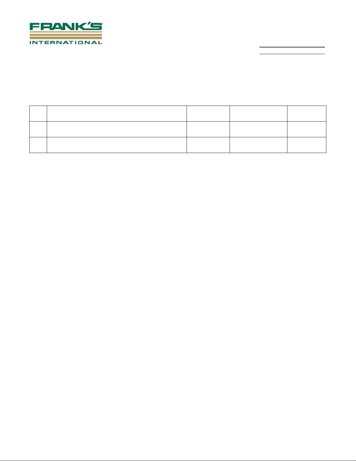
Minimum 33,000 45,000
24
26
28
30
36
38
42
48
Optimum 36,000 48,000
Maximum 39,000 51,000
Minimum 36,000 49,000
Optimum 39,000 52,000
Maximum 42,000 55,000
Minimum 39,000 53,000
Optimum 42,000 56,000
Maximum 45,000 59,000
Minimum 42,000 57,000
Optimum 45,000 60,000
Maximum 48,000 63,000
Minimum 51,000 69,000
Optimum 54,000 72,000
Maximum 57,000 75,000
Minimum 54,000 73,000
Optimum 57,000 76,000
Maximum 60,000 79,000
Minimum 60,000 81,000
Optimum 63,000 84,000
Maximum 66,000 87,000
Minimum 69,000 93,000
Optimum 72,000 96,000
Maximum 75,000 99,000
Table 2
6.0 Records
Equipment Fault Report - GEN-QR-003
7.0 Reference Documents
7.1 Internal Documents
7.1.1 Frank’s Drawing Number 82041 – 36” 3 Point Lifting Chain with Foundry Hooks
7.1.2 Frank’s Drawing Number SOG199905104 – DDS Protector Spade Breaker Bar
7.1.3 Frank’s Drawing Number SOG199905105 – DDS Protector Breaker Bar
7.1.4 Frank’s Drawing Number SOG199905095 – 1” – 1-1/4” Kevlar Rope Assembly
7.1.5 Frank’s Drawing Number SOG199905097 – 1-1/2” – 2” Kevlar Rope Assembly
Document may be uncontrolled if printed, verify current approved revision before use.
Page 14
Rev. A September 2014
A
Section No: 4.1.32 Page 14 of 14
Prepared By: J. Gaspard
QHSE Integrated Procedure Manual Approved By: QHSE Committee
7.2 External Documents
None
Rev Details of Change
A
Initial Release J. Gaspard QHSE Committee
Prepared By
pproved Date
Sept. 2014
Document may be uncontrolled if printed, verify current approved revision before use.
 Loading...