

Franke PRI54GAVTC Technical Handbook

TECHNICAL HANDBOOK HOB PRI5 4GAVTC XS C UK
SUKEN 4 /5 BURNER HOOB
PRI54GAVTC SATIN FINISH STAINLESS STEEL 6691615
dimension 970x530 cut out 930x490
Table of contents
User's instructions . . . . . . . . . . . . . . . . . . . . . . . . . . . . . . . . . . . . .
Hob cleaning and maintenance . . . . . . . . . . . . . . . . . . . . . . . . . . .
Technical data . . . . . . . . . . . . . . . . . . . . . . . . . . . . . . . . . . . . . . . . .
Installation . . . . . . . . . . . . . . . . . . . . . . . . . . . . . . . . . . . . . . . . . . . .. . .
TO HAVE ACCESS TO THE FUNCTIONAL COMPONENTS . . . .
Exploded view PRI54GAVTC
SPARE PARTS PRI54GAVTC
Exploded view PRI54GAVTC
SPARE PARTS PRI54GAVTC
UPDATED 03.2006
User's instructions
Igniting the burners
In these models the knob controls both ignition and the safety device. Proceed as follows to ignite the burners:
1) Turn the chosen knob.
1
2) Keep the knob strongly pressed in for 3/4 seconds to permit the spark to light the gas that exits from the flametamer and to permit the
thermocouple to heat up.
3) Release the knob after about 3/4 seconds and adjust the flame as desired, rotating the knob anti-clockwise. Repeat points 1 and 2 if the flame
does not remain on.
Symbols
Circle: valve off;
large flame + star: maximum flow rate;
small flame: minimum flow rate.
Using the burners
For greater efficiency and less gas consumption use pots and pans with the right diameters for the burners. Avoid having flames extending out
from underneath the pans (refer to the table).
Table of recommended pans Ø Pan diameter in cm
SMALL from dia. 8 to dia. 14
MEDIUM from dia. 14 to dia. 20
FAST/RAPID from dia. 20 to dia. 28
TRIPLE-RING Above dia. 26
Automatic safety valves
This safety device automatically closes the gas valve if the burner flame accidentally turns off due to drafts, liquids overflowing from pots or
momentary interruptions in the gas supply. The device takes effect approximately 30 seconds after the flame turns off.
Hob cleaning and maintenance
- All parts made of 18/10 stainless steel will remain just like new if they are cleaned with water and then carefully dried.
- To restore their original gloss they should be periodically cleaned using "Franke inox Creme" and "Franke microfibre cloth" available from your
retailer or from a FRANKE Service Center.
- Absolutely never use steel wool or pads, muriatic acid or any other products that can scratch or grind.
- Avoid leaving acid and alkaline substances on the cooktop or objects made of rusted iron.
• Burners or flametamers can be cleaned after removing them from the hob using hot
soapy water and detergent. Then dry them with care. Make sure gas passages are perfectly clean. These components can also be washed in a
dishwasher.
• Pan grillplates in the pan support section change in colour due to the action of heat. To clean them proceed as with the burners or wash them in a
dishwasher.
TYPE OF GAS BURNER INJCTOR MARKING RATED THERMAL REDUCED THERMAL RATED
2
CAPACITY IN
WATTS
G20 NATURAL GAS
METHANE 20 MBAR
G30-G31
LIQUEFIED GAS
30/37 MBAR
Supply voltage: 220/230 V 50 Hz
Overall thermal capacity: see the identification plate on the bottom of the cooktop.
Combustion supporting air: 2 m3/h per kW of installed power - see identification plate.
SMALL
MEDIUM
FAST/RAPID
TRIPLE-RING
SMALL
MEDIUM
FAST/RAPID
TRIPLE-RING
72
97
115
140
50
65
85
91
1000
1750
3000
3300
1000
1750
3000
3300
CAPACITY IN WATTS CONSUMPTION
400
440
800
1600
400
440
800
1600
95 L/H
167
286
314
73 G/H
127
218
240
Installation
Installation and connection to the mains should be carried out in compliance with national laws in force.
The following paragraphs describe installation procedures both for the gas and for the electrical sections. These tasks must be performed
according to current standards and by qualified personnel: performance by inexpert persons can create dangers. The manufacturer
declines all responsibility for harm to persons or property caused by failure to comply with these requirements.
Important
- The appliance must be installed by expert and qualified personnel according to
current standards.
- Turn to a Franke Service Centre for all repairs and maintenance.
- Never use deformed or unstable pots and pans on the burners which could overflow
or tip over.
- If the appliance has a cover make sure the burners are cool before closing the cover.
- Close the gas supply valve when the hob is not being used.
Franke S.p.A. declines all responsibility for harm to persons or property caused by
failure to comply with standards. This appliance can only be used for cooking.
Any tampering with or modification to the appliance can be a source of danger. Make
sure gas distribution systems are as required before installing the appliance. The gas
for which the hob is designed is indicated on the label on the bottom of the control
box. This appliance
3
is not joined to a device for evacuating products of combustion and must be installed and hooked-up according to current regulations.
Special attention must be given to ventilation. The appliance may have hot parts during operation: keep children and the handicapped distant. Use
of gas-fired cooking appliances generates heat and humidity in the room where they are installed. Make sure the room is properly ventilated.
Keep natural ventilation openings free and open or install a mechanical ventilation device (extraction hoods with exhaust ducts). Intense and
prolonged use of the appliance may require supplementary ventilation such as opening a window or taking measures for more efficient ventilation
by, for example, increasing fan powers.
Preparing the cabinet
IMPORTANT: The Franke low-profile hob requires a worktop with a thickness of at
least 40 mm.
If the worktop is lower than 40 mm, for a correct installation put special shims near the
hooks.
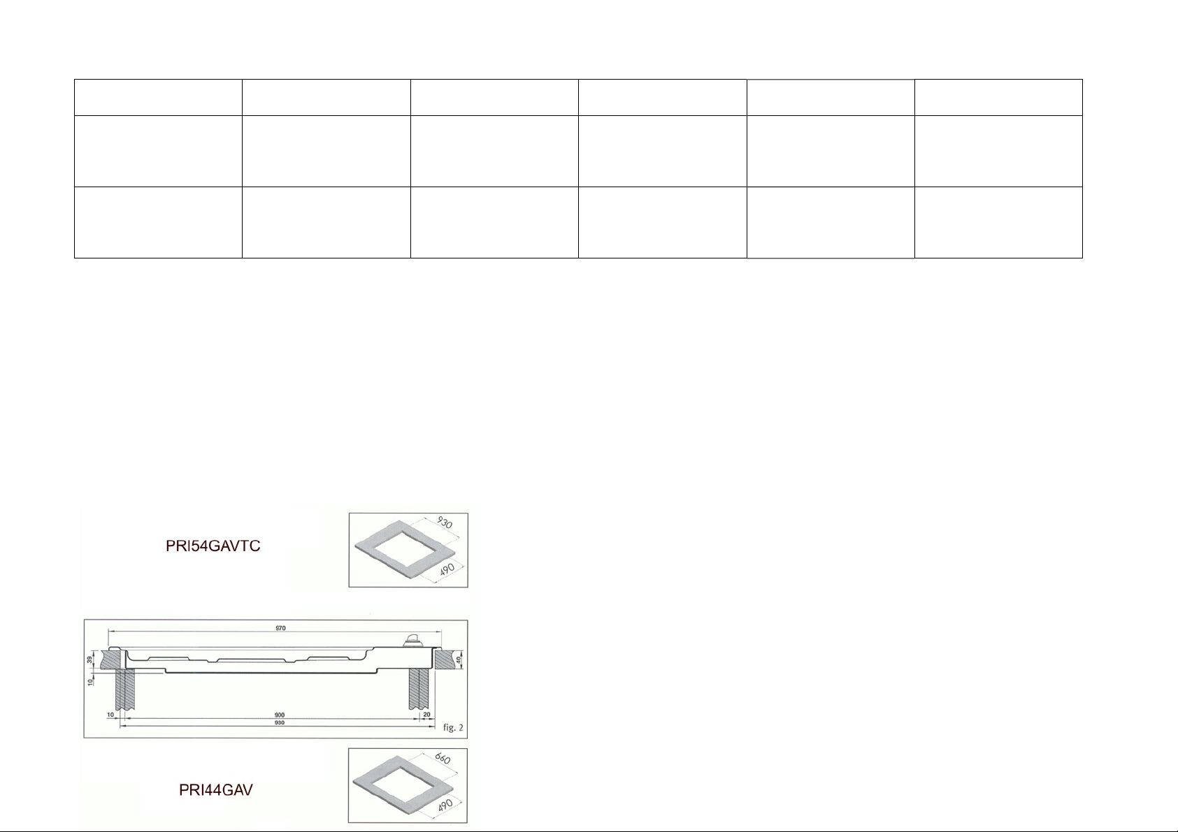
INSTALLING model PRI 5 4GAV-TC (970x530 mm)
Prepare the cut-out in the worktop with the following
dimensions:
When installing the model PRI 5 4GAV-TC hob on a 900 mm base the hob can be
centered on the base (see fig. 2).
Prepare the cut-out in the worktop with the following dimensions: fig. 2
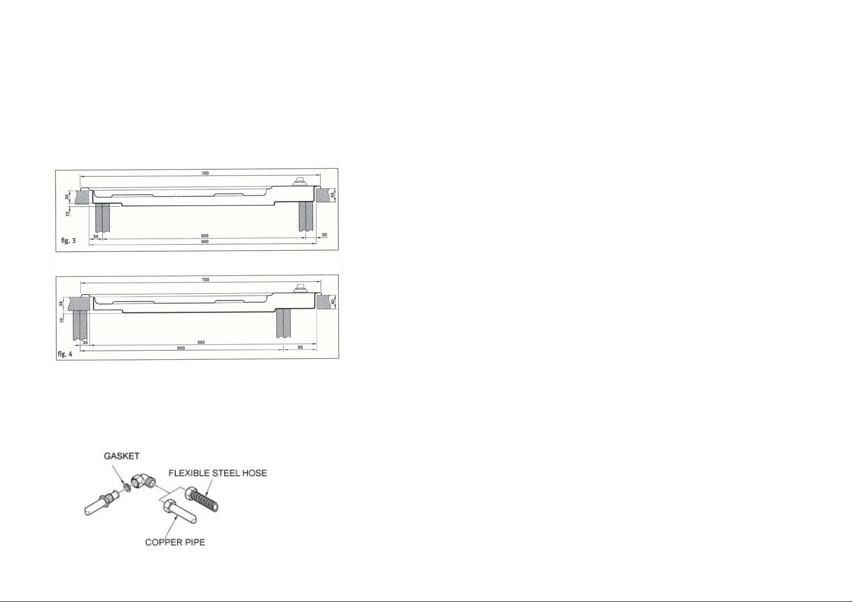
INSTALLING model PRI 4 4GAV (970x530 mm) 14
The PRI 4 4GAV model can be positioned in the center of the base (see fig. 3) when
the base is 600 wide. fig. 3
Otherwise, the hob can be positioned by centering the cooking area (see fig. 4) with
respect to the base. fig. 4
Important
These are "Y" appliances in terms of fire protection. They can be installed built-in even near wooden walls higher than the worktop in which they
are installed as long as there is a minimum distance from the edge of the appliance equal to: 50 mm. for the side wall, 30 mm. for the rear wall and
at least 700 mm from wall cabinets hung over the hob.
Connection to the gas pipeline
There are two ways of making the connection to the gas pipeline:
A) Connect the gas hob using a dia. 12 mm rigid copper tube as illustrated in figure 5. To
guarantee a proper seal insert the elastomer seal provided with the appliance.
B) Connect the hob using a solid wall flexible steel tube. Here, too, you must insert the seal that is
furnished in order to ensure a proper seal. We also recommend compliance with standards
regarding gas-fired appliances.
4
 Loading...