

Franke La Marzocco GB5, La Marzocco FB-70, La Marzocco Linea, La Marzocco FB-80 Training Manual
Franke Coffee Systems
North America Inc
5601 1st Ave South
Seattle,WA 98108
Ph 800.310.5710 Fax 206.782.2124
www.franke-cs.com

La Marzocco Training Manual
The La Marzocco is set apart from most other espresso machines due to its two-boiler system. Having separate coffee and steam boilers allows the machine to achieve and maintain
exceptional thermal balance.
Single boiler espresso machines’ brewing water comes from a heat exchanger located
inside the steam boiler. Brewing water temperature is solely dependent on the pressure of
the water in the boiler used for steaming. As the steam boiler’s pressure rises and falls during normal operation so does the water temperature in the heat exchanger used for brewing.
The LaMarzocco has a separate boiler for each function. A coffee boiler to heat water for
brewing espresso and a steam boiler used to generate steam for preparing milk and hot
water for tea or americanos. This two-boiler system allows for the perfect brewing temp
even if the steam boiler has been under extremely heavy steaming or water usage.

Safety & Tools
Safety Precautions
Before performing maintenance on the steam boiler:
* Turn the machine off.
* Depressurize the steam boiler by opening one or both steam arms.
The only exception would be when rebuilding the steam assemblies, then it will be necessary to close the ball valves located on the steam tank.
Before performing maintenance on the coffee boiler:
* Turn the machine off.
* Turn off the incoming water supply.
* Depressurize the coffee boiler by opening the expansion valve.
When performing maintenance on any electrical wiring in the machine, apart from taking
voltage or amp readings ensure the machine is unplugged from the wall outlet.
Tools
Certain maintenance procedures may require one of the following tools, which are unique
to the La Marzocco.
1. Sight Glass Tool
2. Heating Element Wrench
3. Diffuser Tool (only for machines prior to April 2003)
Other tools required are common tools available at most hardware stores:
* Combination metric wrench set ranging from 10mm to 26mm
* Metric Allen wrench set
* Multi-meter
* 3/16 x 4" Standard screwdriver
* 1/4 x 4" Standard screwdriver
* Stubby standard screwdriver
* #2 Phillips screwdriver
* Mini Screwdriver set
* Fuse puller
* Small wire brush
* Wire stripper/crimpers
* Diagonal cutters
* Slip-joint pliers
* Needle-nose pliers
* Snap-ring pliers
* 6, 8 & 10" Adjustable wrenches
* Teon tape
* Food Grade lube gel
* Fuses - (5 x 20mm) 40mAmp, 125mAmp, 1 amp, 10amp and 6.3 amp
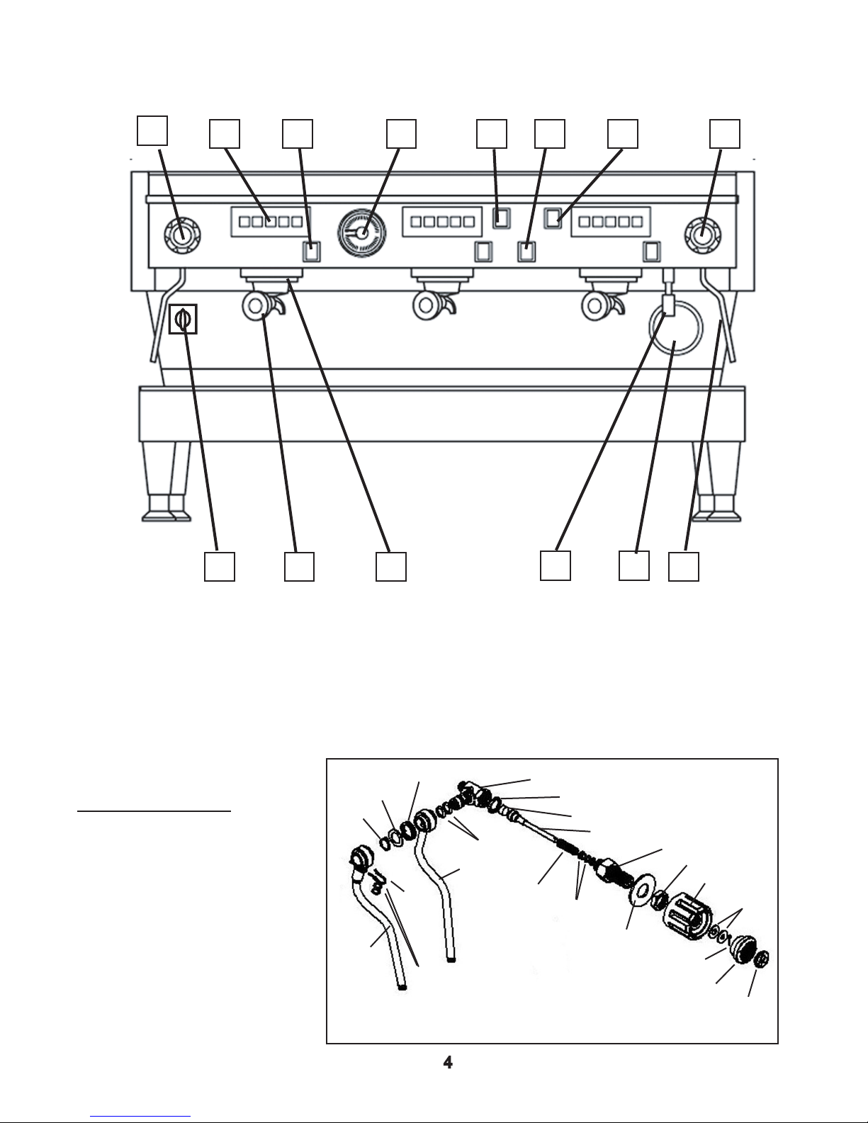
Machine Overview, Linea
1
4 3 2
8 7 6 5
10 9
11
12 13
1. Steam Knob, Left 8. Steam Knob, Right
2. Keypad 9. Main Switch
3. Semi-automatic Dispense Switch 10. Portalter
4. Dual-scale Pressure Gauge 11. Group Head
5. Coffee Boiler Heating Element Indicator Light 12. Hot Water Nozzle
6. Hot Water Dispense Switch
13. Sight Glass
14. Steam Wand
Steam Valve Body
Crush Washer
Steam End Gasket
Steam Shaft
Shaft Spring
Shaft O-Rings
Washer
1 & 8 Steam Knobs
The steam knob allows the
barista to open and close the
steam assembly to prepare the
milk used in milk-based drinks.
Washer
Circlip
Swivel
Steam
Wand
Wand
Spring
Wand O-Rings
Steam Wand
Hairpin
Clip
Wand
O-Rings
14
Steam Valve Housing
Mounting Nut
Knob
Washers
Cotter Pin
Bezel
Insert

2. Keypads
BOILER
PRESSURE
DISPENSING
PRESSURE
0,5
1
1,5
2
2,5
3
15
12
9
3
6
The keypads contain up to four seperate product buttons, single ristretto, single shot,
double ristretto, and double shot. Generally, the buttons are programmed to dispense 3/4
oz, 1 oz, 1-1/2 oz, and 2 ounces respectively, but they can be programmed to any desired
volume.
3. Semi-Automatic Dispense Switch
The semi-automatic dispense switch allows you to brew with the machine while bypassing the electronic keypads. Activating the switch sends power directly to the group
valve allowing water to ow through the group head. This switch is generally used when the
fuse in the control box has blown.
4. Dual-Scale Pressure Gauge
The pressure gauge is divided into two sections,
top and bottom. The top portion of the gauge reads
the steam pressure in the rear boiler. The steam
pressure is factory set to 1.2 bar. The bottom
portion of the gauge reads the brewing pressure in
the front boiler. The gauge will read the static water
pressure going to the espresso machine, when the
machine is turned off. When the machine is turned
on, the heating elements will activate, heating the
water in both boilers. As the water heats up in the
front boiler, it expands. The front boiler is a closed,
totally saturated vessel, with no room for the water to
expand into. This causes the pressure to increase,
evidenced by the bottom protion of the gauge
climbing. Once the gauge needle reaches 12 bar,
the expansion valve, located in the drain box,
should unseat and prevent the pressure from climbing higher than 12 bar. If the gauge does
not reach or exceeds 12 bar, adjust the barrel of the expansion valve accordingly.
5. Coffee Boiler Heating Element Indicator Light
This red light illuminates whenever the heating element in the front, or coffee, boiler is
activated. When the water in the coffee boiler reaches the temperature the thermostat has
been set to, the thermostat will cut power to the heating element and the light will go out.
During initial machine start-up, wait for this light to go out before brewing.
6. Hot Water Dispense Switch
Depressing this switch activates the hot water solenoid valve, allowing the valve to open
and water from the steam boiler to exit the hot water nozzle. Steam pressure must be
present in the steam boiler to force water through the valve.
7. Manual Fill Switch
Depressing this switch activates the auto-ll valve, allowing cold water to ow into the
steam boiler. This switch would only be used if the fuse in the control box has blown.
9. Main Switch
The main power switch has three positions: OFF, FILL and RUN (or 0,1,2 on older machines.)
Off - The machine is off
Fill - The electonics are activated, but NOT the heating elements. This allows the machine
to auto-ll prior to the elements heating up.
Run - The electronics as well as the heating elements are activated allowing the machine to
build steam pressure and the coffee boiler to heat up.
10. Portalter
The portalter holds the ground coffee dosed from the grinder. The portalter, dosed and
tamped with coffee is then inserted into the group head to brew espresso.
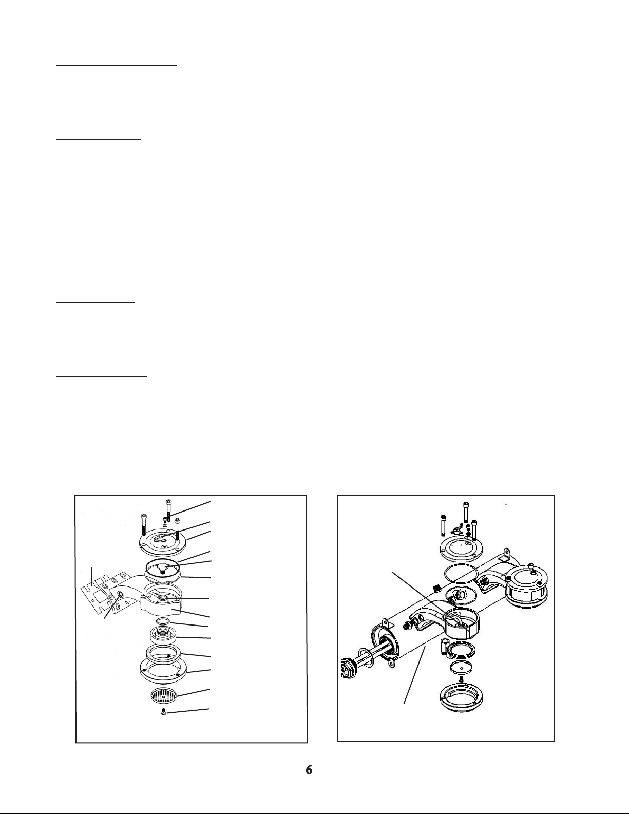
11. Group Head
The group head is where the brewing water meets with the ground coffee in the portalter
to brew espresso.
The La Marzocco’s group head is called a saturated group. It is either a nickle-plated brass
group, (machines manufactured prior to March 2003) or a stainless steel group, (machines
manufactured from March 2003 to the present).
Brass Group
Group to Boiler
Gasket*
Exit port to Flowmeter
Bleed Screw
Thermal Limiter
Group Cap
O-ring
Banjo Bolt
Fiber Gasket
Banjo Tube
Group Head
O-ring
Diffuser Block
Portalter Gasket
Bayonet Clamp Ring
Stainless Group
The banjo tube has been
redesigned, the banjo bolt is
no longer required.*
Diffuser Screen
Diffuser Screw
Group is welded
to the boiler*
12. Hot Water Nozzle
The hot water nozzle is installed on the outlet of the hot water valve. When the valve is
energized, hot water from the steam boiler is forced, by steam pressure, through the valve
and out of the nozzle.
13. Sight Glass
The sight glass indicates the amount of water in the steam boiler only,as the coffee boiler is
always fully saturated with water. The sight glass should read between 2/3 and 3/4 during
normal operation.
Body
O-ring
Glass
Fiber Gasket
Securing Bezel
Fitting
Washer
Bleed Screw
14. Steam Wand
The steam allows the barista to prepare milk for drinks suchs as lattes, cappuccinnos, and
mochas. The La Marzocco uses stainless steel wands that rotate 360 degrees.
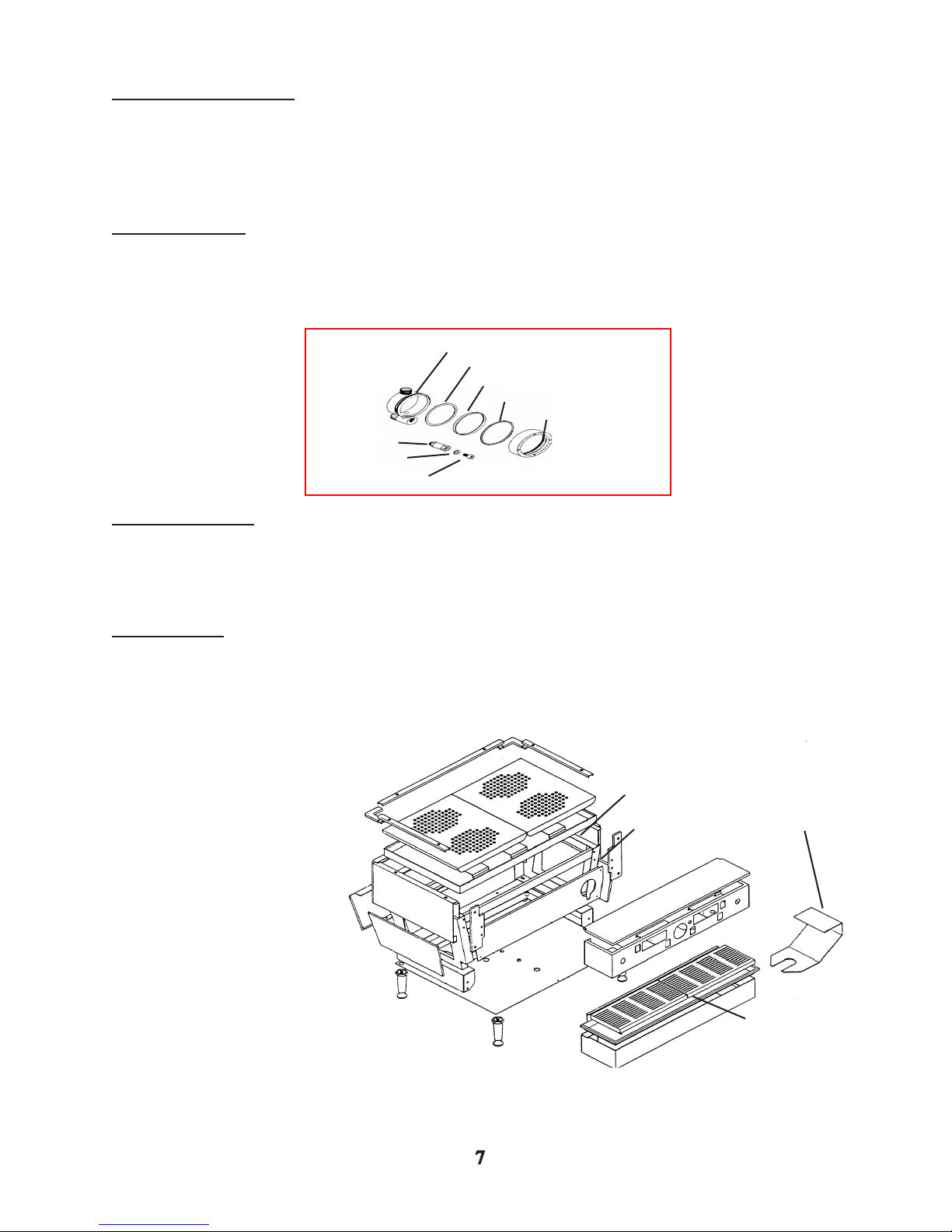
Body Panels
For most repairs, it may be necessary to remove a body panel.
1. Top Trim
2. Upper Surround Panel
3. Left Side Panel
4. Right Side Panel
5. Front Panel
1
6
7
4
Steaming
6. Cup Tray
7. Cup Tray Grates
8. Group Cover
2
5
8
9. Drip Tray & Grates
3
9

Installation
Contents
When unpacking the machine, the following items should be included:
* 4 NSF Legs (6 for a 4 group machine)
* Pump & motor assembly
* Portalters
* Drain Hose
* Tamper
* PuroCaff Cleaner
* Owners manual
* Inlet hoses, 24”, 48”, and 84” lengths
* Warranty card with water test strip attached
Water Requirements
A dedicated water line with its own shut-off valve should be placed within four feet of machine instal-
lation location. The shut-off valve should be equipped with a male 3/8 compression tting.
The machine operates best with water between 0-3 grains of hardness. Higher hardness levels may
cause damage due to scale forming inside the machine. If the supply water has a hardness above
3 grains per gallon install the appropriate water softener. ENSURE ALL SOFTENING/FILTERING
CARTRIDGES HAVE BEEN ADEQUATELY FLUSHED BEFORE CONNECTING TO THE MACHINE.
ESI recommends our H2O for Espresso system. This cartridge provides both a carbon block to lter
out tastes and odors as well as ion exchange resin for softening of the incoming water. The cartridge also incorporates a 20% bypass to neutralize the pH allowing for a water “recipe” that provides the best tasting espresso.
In some areas of the country, the use of a Reverse Osmosis system, is necessary. When using an RO system, ensure a small percentage of raw water bypasses the RO system and is then
reintroduced into the RO water fed to the espresso machine. This helps prevent corrosion due to
aggressive water properties. The “postmix” water should then be fed through a carbon block lter to
remove tastes and odors.
Power Requirements
The following voltages and amperage ratings apply.
* 1AV OR EE – 208 - 240v, 20amp
* 2AV OR EE– 208 - 240v, 30amp
* 3AV OR EE– 208 - 240v, 50amp
* 4AV OR EE– 208 - 240v, 50amp
There are two electrical cords attached to the machine. The smaller diameter cord supplies pow-
er to the pump motor assembly and should be connected to the pump motor, NOT plugged
into a wall outlet.
Drainage Requirements
Ensure the drain hose provided with the machine runs downhill to an appropriate oor drain.

First time machine start-up
Once the machine has been properly installed:
* Turn on the water supply.
* The coffee boiler(s) will automatically begin to ll.
* Locate the group caps and loosen the bleed screw 1/4 turn until a water bead is visible.
Once a water bead is visible, re-tighten the bleed screw snugly.
* Once the groups have been bled, turn the main power switch to the FILL position. Within 6
seconds, the rear (steam) boiler will automatically begin to ll .
* Once the rear (steam) boiler has lled, (check the sight glass to ensure the rear boiler has
lled to the appropriate level, between 2/3 - 3/4 full), turn the main power switch to
the RUN position.
* While the boilers are heating, press any dispense switch and ensure the pump pressure
(bottom scale of the gauge) reads 9 bar while dispensing. Adjust if necessary.
* Wait for the boilers to heat fully indicated by the coffee boiler heating light going off and the
top scale of the pressure gauge reaching 1.2 - 1.5 bars.
Pre-infusion
Pre-infusion is the dampening of the coffee grounds allowing them to expand in the portalter prior
to the actual brewing process beginning. This seems to improve the coffee avor of single shots.
To program the machine to pre-infuse, perform the following:
* Turn the main power switch to the OFF position.
* While holding the far left (single ristretto) button on the left most keypad turn the power
switch to FILL.
* The light above the “Swirl” button will illuminate indicating that the control box has received
the pre-infusion command.
To disable pre-infusion, perform the following:
* Turn the main power switch to the OFF position.
* While holding the second button on the left most keypad turn the power switch to the FILL
position.
* The light above the “Swirl” button will illuminate indicating that the control box has received
the pre-infusion command.
Programming
* Using the left most keypad, depress and hold the continuous pour (swirl) button for about 5
seconds.
* Once all of the lights on the keypads begin blinking press the button you wish to program.
* Once the desired volume has been reached, (measure from the bottom of the crema),
push the button again.
* Repeat this procedure for each button.
*Any programming performed on the left group will carry over to all of the groups to the
right. After programming the left group, verify that groups to the right are dispens
-ing the proper volume. You can also individually program the right groups without
affecting the others.

Temperature and Pressure Adjustments
Machines ship from ESI with the coffee boiler thermostat adjusted to heat and brew water for
espresso at 197 degrees Fahrenheit or 92 degrees Celsius. If you prefer to adjust the tempera-
ture to t your coffee roast perform the following:
* Make certain that the machine is at operating temperature and that the coffee boiler
heating indicator light is off.
* Remove the top cover from the machine and locate the thermostat between the groups.
* Turn the main switch to the OFF position.
* Using a long insulated screwdriver adjust the thermostat clockwise to increase tempera
ture and counter-clockwise to lower temperature.
* This adjustment is very sensitive and only slight adjustments should be made. Each 1/4
turn represents a 3 degree Fahrenheit temperature change.
*Turn the main switch back to the RUN position.
If your steam pressure gauge does not read 1.2 bar, adjust the pressure switch as follows:
*Turn the main switch to the OFF position.
* Remove the top panel of the machine.
* Locate the pressure switch in the back, top, left-hand corner of the machine.
* For machines equipped with Sirai pressure switches (Rectangular switch approximately
2” x 4”), remove the screw and lift cover from pressure switch to access the adjust
ment screw. There will be arrows pointing towards - and +. Turn towards - to lower
the steam pressure and turn towards + to raise steam pressure.
* For machines equipped with Giemme pressure switches (Round switch approximately
1-1/4 in diameter), locate the samll adjustment screw in the center of the switch
and adjust very delicately towards - to decrease the presure and + to increase the
presure.
*Turn the main switch back to the RUN position.

Section 1 Questionnaire
1. What’s unique about the La Marzocco espresso machine compared to other traditional machines
on the market?
2. Why are two boilers in an espresso machine better than having only one?
A. The heat exchangers require less maintenance.
B. More stable brewing temperature.
C. The machine uses less electricity.
D. You can operate the machine at a higher steam pressure.
3. What safety precautions must be carried out before performing maintenance on the coffee boiler?
A.
B.
C.
4. What are the three special La Marzocco tools?
A.
B.
C.
5. There are two electical cords coming out of the machine. What are each of them for?
6. What must you do to the coffee boiler after initial installation before you operate the machine?
7. Explain why the bottom portion of the pressure gauge travels up and down between 3 bar and 12
bar during normal operation?
8. What design change allows for a more stable and effecient brew temperature on machines
manufactured after March 2003?
9. How should the water supplying the machine be treated to ensure its quality?

10. What are the proper steps to take when programming the machine?
A. Turn the machine offand hold down the continuous pour button while turning the machine
on.
B. Press and hold the continuous pour button until the LED above the button illuminates.
Then press the button you wish to program.
C. Press the continuous pour and the button you wish to program at the same time. When
the lights blink, press the button you wish to program again.
11. Which keypad do you program to facilitate programming of the entire machine?
12. Why don’t we generally recommend using water treated by reverse osmosis, except in extenuating circumstances?
A. It’s more expensive and complicated to use than lter/softening cartridges.
B. It can cause the water to become very agressive, causing corrosion.
C. It can remove too much of the TDS in the water, causing the auto-ll system to not func-
tion properly.
D. The coffee usually doesn’t taste as good.
13. If circumstances require you to use RO water, what step should you take to alleviate the negative side effects of RO water in espresso machines?
14. Explain the three positions of the main power switch.
A. Off -
B. Fill -
C. Run -
15. What does the red light on the machines control panel indicate when illuminated?
16. How do you initiate the pre-infusion feature of the La Marzocco?
4. Hydraulic System
Tubing and ttings
* Virtually all of the ttings on the LaMarzocco are of the compression or are type. Most are made
from brass, which will strip or crack if over-tightened.
* It is important when working with tubing not to bend or twist the sections you are working with, as
this will restrict the water ow or cause fatigue or leaks in the tubing.
Boilers & Groups
The La Marzocco uses hollow plated brass group castings attached to a stainless steel boiler on
machines manufactured prior to March 2003, and stailess steel groups welded to the boiler on machines manufactured beginning March 2003.
*In auto-volumetric models, the water from the group exits through a small tube on the left side of
the group and ows to the owmeter, which meters the volume of the water. From the
owmeter the water passes through to the group valve. From the group valve, the water
then ows back into a small tube inside of the group head and then to the diffuser block, the
diffuser screw, diffuser screen and nally to the ground coffee in the portalter
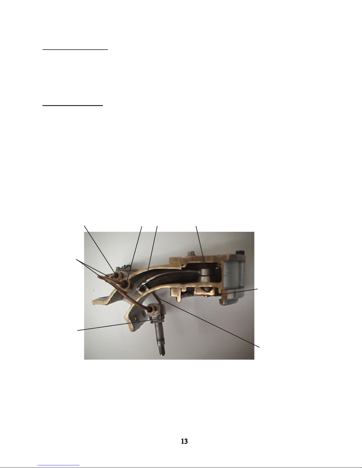
Below is a cutaway of a grouphead. Below the photo is the sequence of water ow through the
group to the portalter.
2
1
6
7
3
8
4
5
1. Water exits the group head and travels through a tube to the owmeter.
2. Water enters the owmeter and rotates the impellor.
3. Water exits the owmeter and travels through a tube to the group valve.
4. Water passes through the group valve...
5. And travels through a tube to the banjo tube inlet.
6. Water enters the banjo tube and ows to the banjo bolt.
7. Water passes through the banjo bolt and down towards the diffuser block.
8. Water passes through the diffuser block and enters the diffuser screw and screen where it
then meets with the tamped coffee in the portalter.
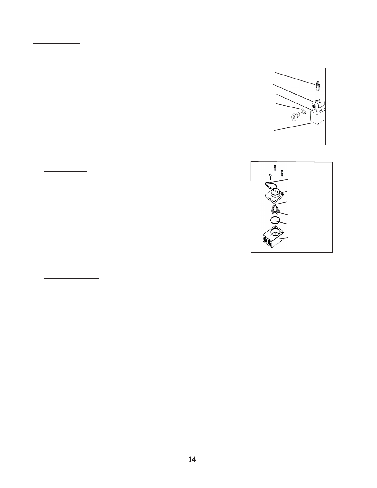
Group Valves
Each group has a three-way solenoid valve mounted underneath each head to allow for water
ow through the group.
* Each valve consist of valve body, valve stem, spring-loaded
piston and a coil.
* The valve is mechanically closed by spring pressure.
* The coil receives electrical power when the brew switch or
keypad is depressed.
* When energized, the coil creates a magnetic eld which opens
the piston, allowing water to ow through the valve body.
* When the valve closes, pressurized water from the valve outlet to
Valve Piston
Valve Body
Solenoid Coil
Brass Washer
Fitting for tube from
Flowmeter
Valve Shaft
the diffuser block discharges through the bottom of the
valve stem to the drain box.
Flowmeters
Ground Wire
The owmeters measure the volume of water passing through to the
groups.
* The Flowmeter is made up of an electromagnetic eld, an impeller
and a body.
* As water enters the Flowmeter body it causes the impeller to
rotate. The impeller has two small magnets imbedded in it.
As the impeller spins, the magnets pass the magnetic eld,
causing a switch to close, which sends a pulse signal to the
microprocessor.
Flowmeter Field
Magnets
Impellor
O-ring
Flowmeter Body
Autoll System
The autoll system maintains the water level in the steam boiler.
* The autoll system consists of an autoll circuit on the control box, an auto-ll probe and an
autoll valve.
* The autoll probe is a metal probe, which sticks down into the boiler. An electrical lead is at
tached to the top of the probe, approximately 1-2 vac travels through this probe from the
control box.
* As the water rises in the boiler, and reaches the probe, the 1-2 vac travels through the water
and grounds itself against the sidewall of the boiler. When this ground signal travels back
to the control box, it signals the auto-ll circuit to switch off the auto-ll valve.
* As water is depleted from the boiler it lowers below the probe causing the signal to be inter-
rupted. When the auto-ll circuit can no longer read a ground signal, it activates the
autoll valve allowing water to enter the boiler.
* The autoll valve consist of an electromagnetic coil and a valve.
* The valve is mechanically closed by spring tension. When the coil is energized it creates a
magnetic eld, which pulls the valve piston open, allowing water to pass through it.
Vacuum Breaker
The vacuum breaker is a mechanical valve located on the steam boiler.
As pressure builds in the boiler, steam pressure lifts a plunger, sealing
the boiler, allowing steam pressure to increase above atmospheric
pressure.
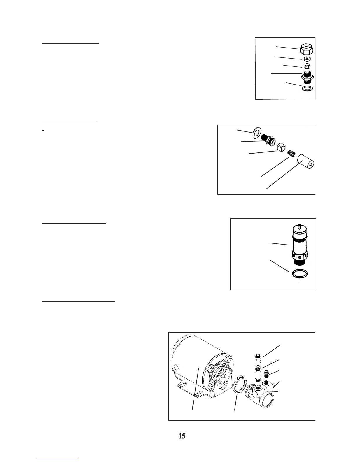
Expansion Valve
The expansion valve relieves front boiler pressure at 12 bar.
* The expansion valve is located in the drain box, which is
underneath the drip tray.
*It consists of a valve body, a valve seal and spring, which
are enclosed by an adjustable brass barrel.
*The expansion valve is adjusted by adding or relieving
tension on the spring by turning the adjusting barrel.
Washer
Body
Valve
Seal
Top Cap
Gasket
Teon Cone
Body
Brass Washer
Spring
Barrel
Safety Relief Valve
The pressure relief valve relieves boiler pressure at 1.8 bar
preventing the boiler from over-pressurizing. It is factory
adjusted and sealed and cannot be adjusted.
External Boost Pump
The boost pump increases existing water
pressure to 135 psi or 9 bar, which is
required to properly brew espresso.
* The pump pressure can be adjusted by
adjusting the screw on the side of
the pump.
* Rotating the screw clockwise will
increase pump pressure, while
rotating counter-clockwise will
decrease pump pressure.
*Ensure your waterline is stable, as
uctuations in line pressure will
affect output pressure.
Motor
Relief Valve
Brass Washer
Outlet
Fitting
Check Valve
Inlet Fitting
Adjustment Screw
Pump
Clamp
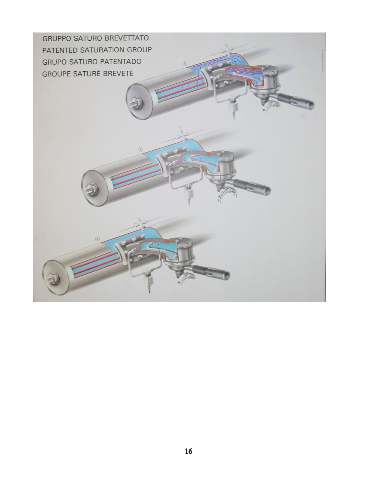
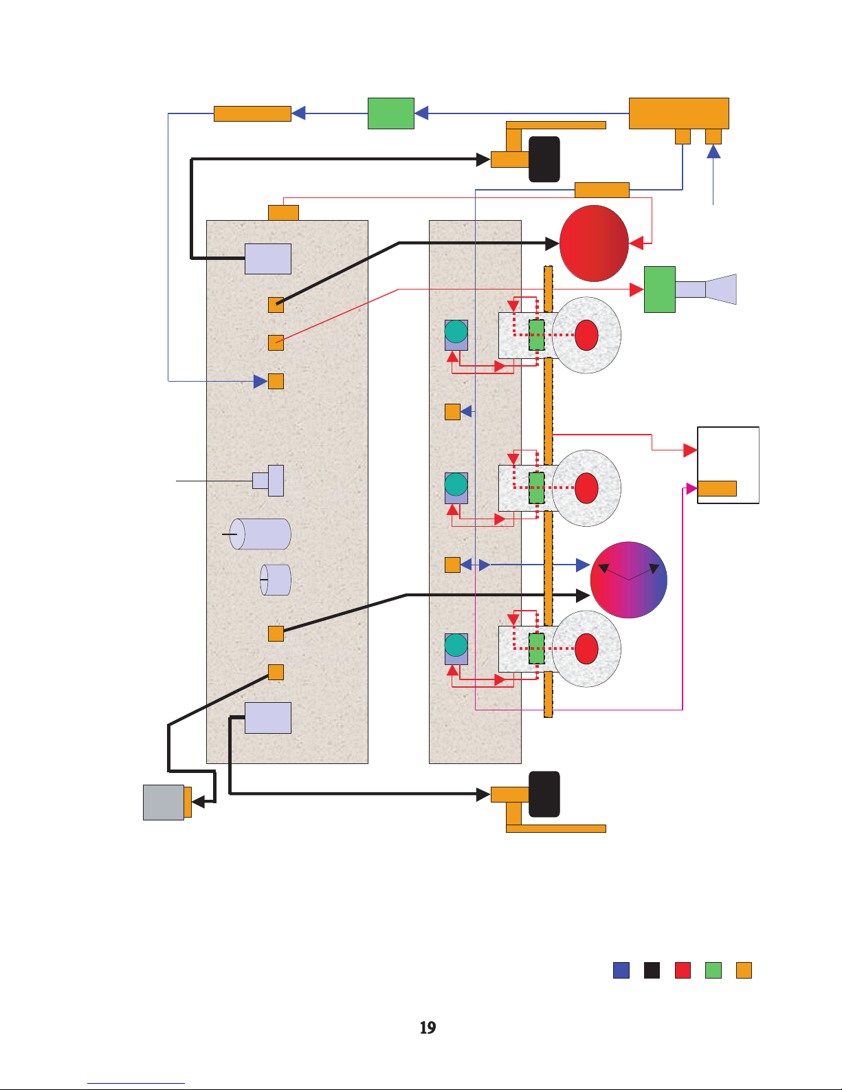
* Note - The boilers shown are from an EE, semi-automatic machine, an AV model would have
owmeters.
1. Circulation of water within the boiler and group head.
2. Water ow during the brew cycle.
3. Discharge of water after completion of brewing cycle.
1 2 3 4 5 6
97 10
8
12 13 14 18
1511 16 17 19
2420 25 26 2821 22 23 27 29
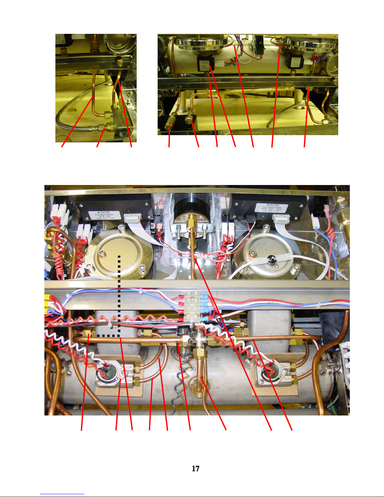
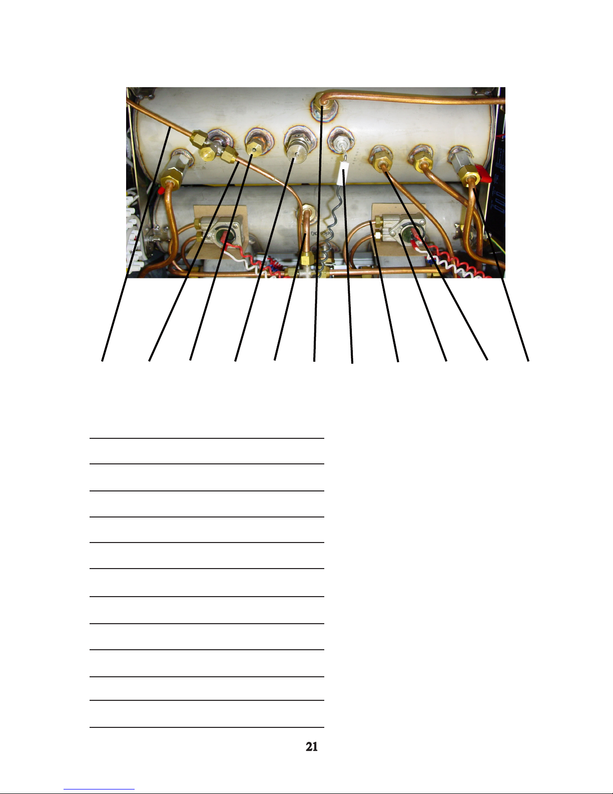
Hydraulic Lines and Components
1. Inlet water tube to the coffee boiler.
2. Inlet water line feeding the inlet manifold.
3. Inlet water tube to the steam boiler.
4. Expansion valve.
5. Discharge tting.
6. Discharge from the 3-way group valve.
7. Group valve.
8. Tube feeding water from the group valve to the banjo tube.
9. Tube feeding water from the owmeter to the group valve.
10. Check valve for the coffee boiler.
11. (Same tube as #8).
12. Flowmeter.
13. Banjo tube (located inside of the group head).
14. Tube feeding water from the group to the owmeter.
15. Tube feeding water from the owmeter to the group valve.
16. Tube feeding water from the coffee boiler check valve to the “X” tting.
17. Tube feeding water into the coffee boiler.
18. Tube feeding water to the gauge.
19. Tube feeding water to the expansion valve.
20. Tube feeding steam to the right steam assembly.
21. Tube feeding the top of the sight glass.
22. Tube feeding water to the hot water valve.
23. Tube feeding water to the steam boiler.
24. Auto-ll probe.
25. Pressure relief valve.
26. Vacuum breaker
27. Tube feeding steam to the pressure gauge.
28. Tube feeding steam to the pressure switch.
29. Tube feeding steam to the left steam assembly.
1
19
10
8
7
6
5
4
3
2
18
17
16
15
14
13
11
12
1111
1818
Brass Fitting/Tubing
Cold Water
Hot Water
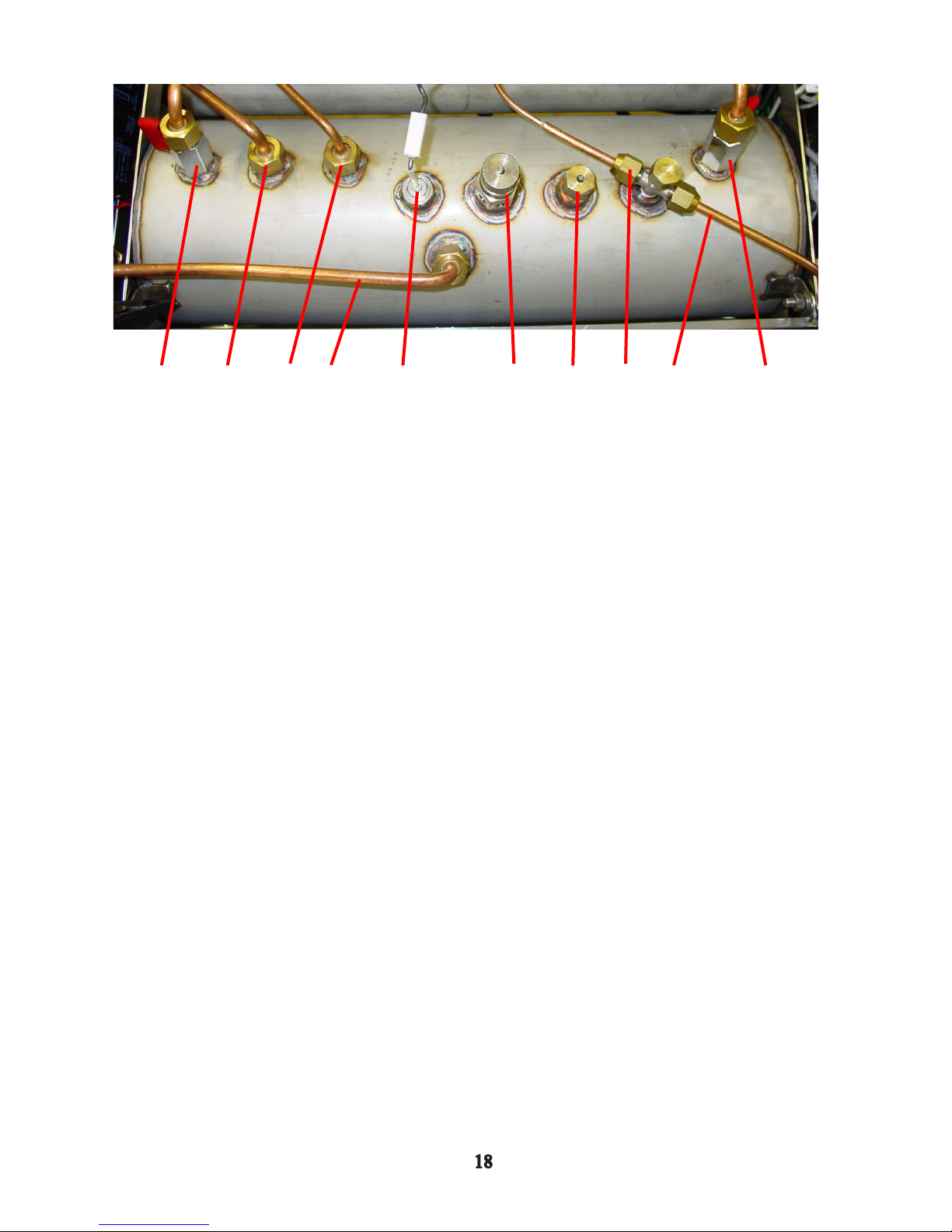
1. Water Inlet
2. Auto-fill Valve
3. Inlet Check Valve
4. Left Steam Assy. Valve
5. Vacuum Breaker
6. Safety Valve
7. Auto-fill Probe
8. Right Steam Assy. Valve
9. Pressure Switch
10. Left Steam Assembly
11. Flowmeter
12. Dual Scale Gauge
13. Hot Water Valve
14. Sight Glass
15. Right Steam Assembly
16. Expansion Valve
17. Group Valve Drain Tube
18. Group Valve
19. Drain Box
20. Check Valve
21. Banjo Bolt
Solenoid Coil
Steam
20
21 2121
LaMarzocco Hydraulic Schematic
9

Section 2 Questionnaire
1. What material are the machines tubes made from? What precaution should you take in working
with them?
2. What is the order of water ow while brewing in an AV machine?
A. Banjo tube, group, owmeter, group valve, diffuser block.
B. Group, owmeter, group valve, banjo tube, diffuser block.
C. Flowmeter, banjo tube, group, group valve, diffuser block.
D. Diffuser block, banjo tube, group valve, owmeter, group.
3. Explain how the machine maintains the water level in the steam boiler.
4. What does the vacuum breaker do?
5. Why must the group valve be a 3-way valve?
6. What problem can cause damage to the machine’s entire hydraulic system?
7. What products are dispensed from the steam boiler?
8. When backushing the machine, what specic areas of the hydraulic system are being cleaned?
9. Describe what kind of water should be fed to the espresso machine.
A B
10. Identify the hydraulic compents in the above picture.
A.
B.
C.
D.
E.
F.
G.
H.
I.
C D
E F G H I J K
J.
K.
 Loading...