

Page 1

Instructions for use and installation
Cooker Hood
Istruzioni per l’uso e l’installazione
Cappa
Mode d’emploi et installation
Hotte de Cuisine
Bedienungsanleitung und Einrichtung
Dunstabzugshaube
Kullan
ım ve montaj talimatları
Davlumbaz
FKU 908-H I TC
GB
IT
FR
DE
TR
Page 2

EN
2
2
Instructions Manual
INDEX
RECOMMENDATIONS AND SUGGESTIONS......................................................................................................................7
CHARACTERISTICS..............................................................................................................................................................8
INSTALLATION ....................................................................................................................................................................10
USE.......................................................................................................................................................................................14
MAINTENANCE....................................................................................................................................................................15
Page 3

IT
3
3
Libretto di Istruzioni
INDICE
CONSIGLI E SUGGERIMENTI ............................................................................................................................................18
CARATTERISTICHE............................................................................................................................................................19
INSTALLAZIONE..................................................................................................................................................................21
USO......................................................................................................................................................................................25
MANUTENZIONE.................................................................................................................................................................26
Page 4

FR
4
4
Manuel d’Instructions
SOMMAIRE
CONSEILS ET SUGGESTIONS ..........................................................................................................................................29
CARACTERISTIQUES.........................................................................................................................................................30
INSTALLATION ....................................................................................................................................................................32
UTILISATION........................................................................................................................................................................36
ENTRETIEN..........................................................................................................................................................................37
Page 5

DE
5
5
Bedienungsanleitung
INHALTSVERZEICHNIS
EMPFEHLUNGEN UND HINWEISE....................................................................................................................................40
CHARAKTERISTIKEN..........................................................................................................................................................41
MONTAGE............................................................................................................................................................................43
BEDIENUNG.........................................................................................................................................................................47
WARTUNG............................................................................................................................................................................48
Page 6

TR
6
6
Kullanim Kilavuku
IÇERIKLER
TAVSIYELER VE ÖNERILER ..............................................................................................................................................51
ÖZELLIKLER........................................................................................................................................................................52
MONTAJ...............................................................................................................................................................................54
KULLANIM............................................................................................................................................................................58
BAKIM...................................................................................................................................................................................59
Page 7
EN
7
7
RECOMMENDATIONS AND SUGGESTIONS
The Instructions for Use apply to several versions of this appliance. Accordingly,
you may find descriptions of individual features that do not apply to your specific
appliance.
INSTALLATION
• The manufacturer will n ot b e he ld lia ble fo r any da mages res ulting from inc orrec t or
improper inst allation.
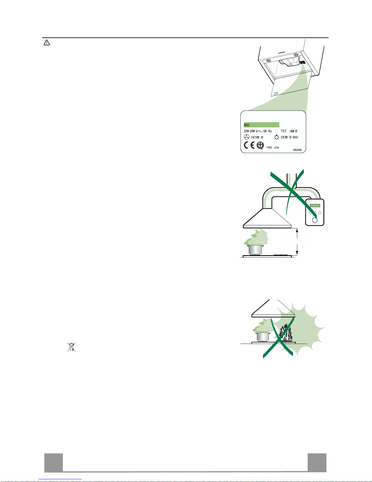
• The minimum safety distance between the cooker top and the extractor hood is 650
mm.
• Check that the mains voltage corresponds to that indicated on the rating plate fixed
to the inside of the hood.
• For Class I appliances, check that the domestic power supply guarantees adequate
earthing.
Connect the extractor to the exhaust flue through a pipe of minimum diameter 120
mm. The route of t he flue must be as s hor t as possible.
• Do not connect the extractor hood to exhaust ducts carrying combustion fumes
(boilers, fi r eplaces, etc.).
• If the extractor is used in conjunction with non-electrical appliances (e.g. gas burning appliances), a sufficient degree of aeration must be guaranteed in the room in
order to prevent the backflow of exhaust gas. The kitchen must have an opening
communicati ng directly with the open air in order to guarantee the entry of clean air.
USE
• The extractor hood has been designed exclusively for domestic use to eliminate
kitchen smells.
• Never use the hoo d f or purposes other t han for which i t has ben designed.
• Never leave high naked flames under the hood when it is in operation.
• Adjust the flame intensity to direct it onto the bottom of the pan only, making sure
that it does not engulf the sides.
• Deep fat fryers must be cont inuously monit ored during use: ov er heated oil can burst
into flames.
• Do not flambè under the range hood; r isk of fire
• This appliance is not intended for use by persons (including children) with reduced
physical, sensory or mental capabilities, or lack of experience and knowledge,
unless they have been given supervision or instruction concerning use of the appliance by a perso n responsible for their safety.
• Children should be supervised to ensure that they do not play with the applian ce.
MAINTENANCE
• Switch off or unplug the appliance from the mains supply before carrying out any
maintenance work.
• Clean and/or repl ace the Filter s af ter the specified time period.
• Clean the hood usi ng a damp cloth an d a neutral li quid detergent.
The symbol on the product or on its packaging indicates that this product may not be treated as
household waste. Instead it shall be handed over to the applicable collection point for the recycling
of electrical and electronic equipment. By ensuring this product is disposed of correctly, you will help
prevent potential negative consequences for the environment and human health, which could otherwise be caused by inappropriate waste handling of this product. For more detailed information about
recycling of this product, please contact your local city office, your household waste disposal service
or the shop where you purchased the product.
650 mm min.
Page 8
EN
8
8
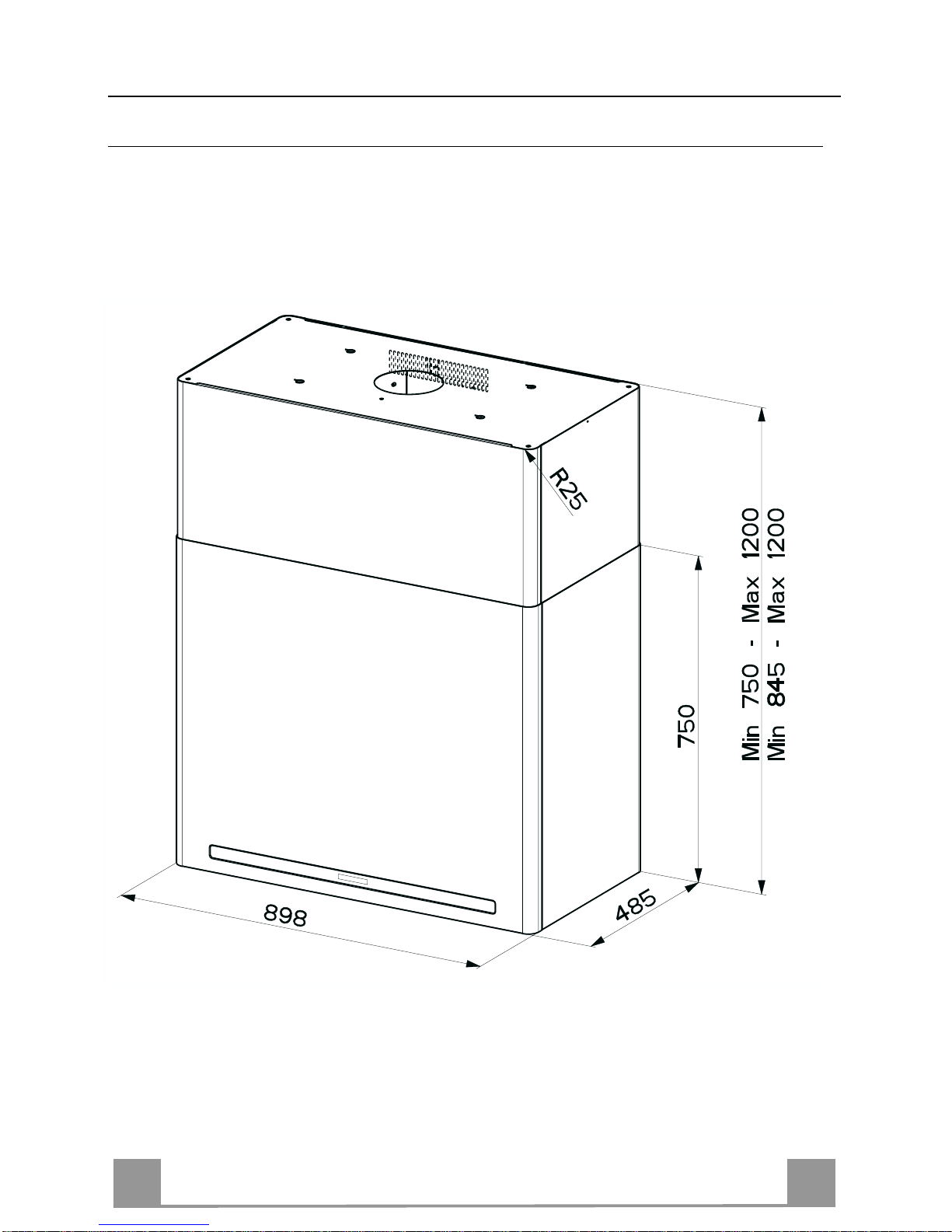
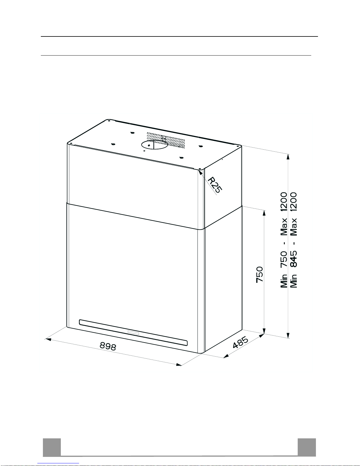
CHARACTERISTICS
Dimensions
*
**
* Dimensions of the hood in ducting version.
** Dimensions of the hood in recycling version.
Page 9
EN
9
9
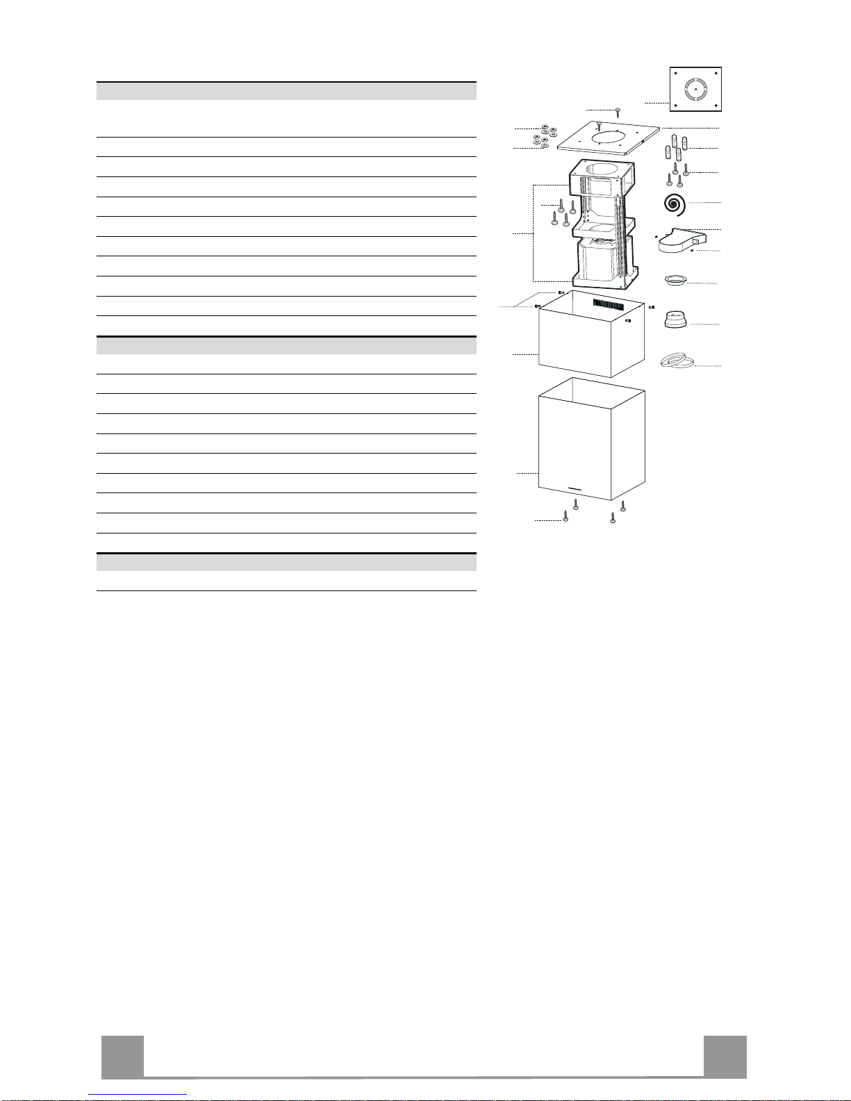
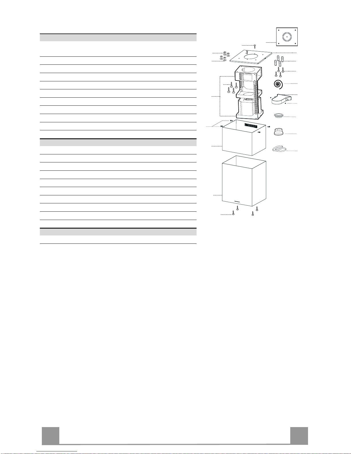
Components
Ref. Q.ty Product Components
1 1 Hood Body, complete with: Controls, Light, Blower,
Filters
2 1 Upper Chimney
7.1 1 Telescopic frame complete with extractor , consisting of:
7.1a 1 Upper frame
7.1b 1 Lower frame
9 1 Reducer Flange ø 150-120 mm
13 1 Gasket
14 1 Hood Body Ai r Outlet Ext ension Piece
15 1 Air Outlet C onnection
25 2 Pipe clamps
26 1 Fixing Part of the upper Chimney
Ref. Q.ty Installation Components
11 4 Wall Plugs ø 10
12c 4 Screws 2,9 x 9,5
12f 4 Screws M6 x 15
12g 4 Screws M6 x 80
12h 4 Screws 5,2 x 70
12w 2 Screws M3 x 8
21 1 Drilling template
22 4 6.4 mm int. dia washers
23 4 M6 nuts
24 2 Fixing knobs for the air outlet connection piece
Q.ty Documentation
1 Instruction Manual
23
22
12h
11
15
24
1
12f
2
7.1
7.1b
7.1a
21
12g
12w
14
26
12c
13
9
25
Page 10
EN
110
INSTALLATION
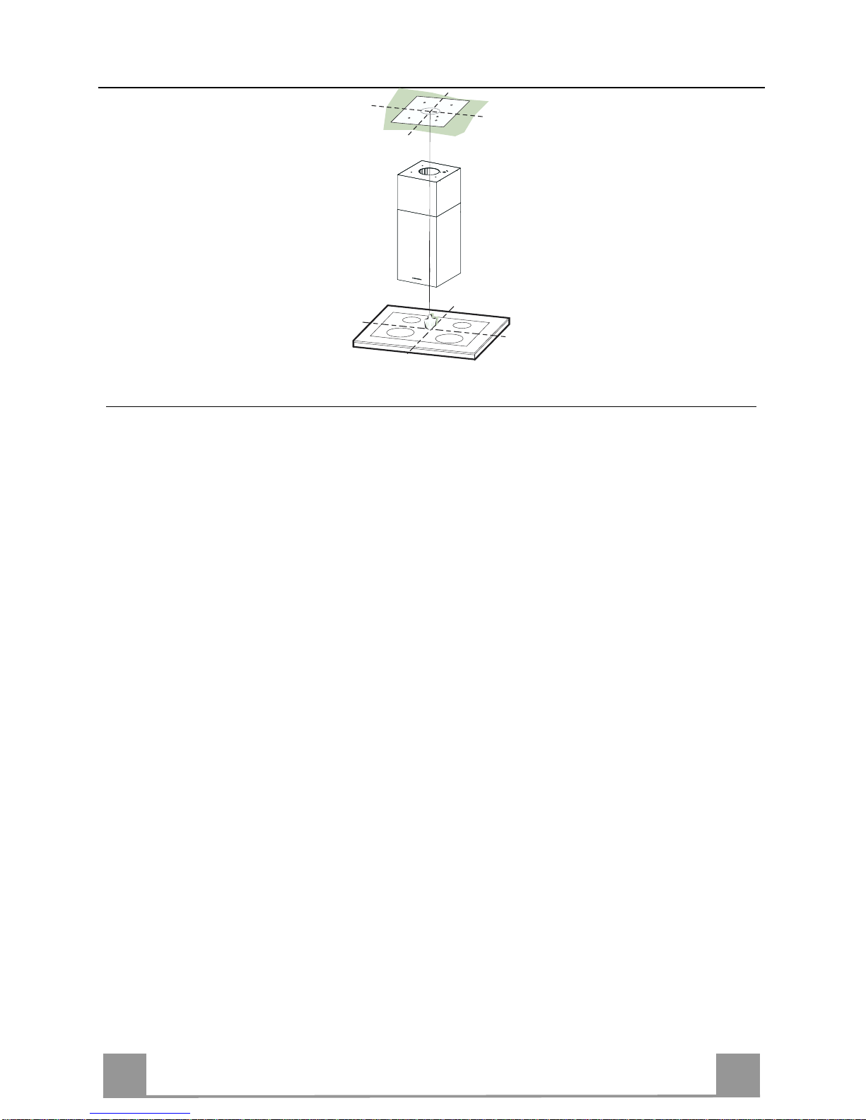
Drilling the Ceiling/shelf and fixing the frame
DRILLING TH E CEILING/SHELF
• Use a plumb line to mark the centre of the hob on the ceiling/support shelf.
• Place the drilling template 21 provided on the ceiling/support shelf, making sure that the
template is in the correct position by lining up the axes of the template with those of the hob.
• Mark the centres of the holes in the template.
• Drill the holes at the points marked:
• For concrete ceilings, drill for plugs appropriate to the screw size.
• For hollow brick ceilings with wall thickness of 20 mm: drill ø 10 mm(immediately insert
the Dowels 11 supplied).
• For wooden beam ceilings, drill according to the wood screws used.
• For wooden shelf, drill ø 7 mm.
• For the power supply cable feed, drill ø 10 mm.
• For the air outlet (Ducted Version), drill accord ing to the diameter of the extern al air exhaust duct connection.
• Insert two screws of the following type, crossing them and leaving 4-5 mm from the ceiling:
• For concrete ceilings, use the appropriate plugs for the screw size (not provided).
• for Cavity ceiling with inner space, with wall thickness of approx. 20 mm, Screws 12h,
supplied.
• For wooden beam ceilings, use 4 wood screws (not provided).
• For wooden shelf, use 4 screws 12g with washers 22 and nuts 23, provided.
Page 11
EN
111
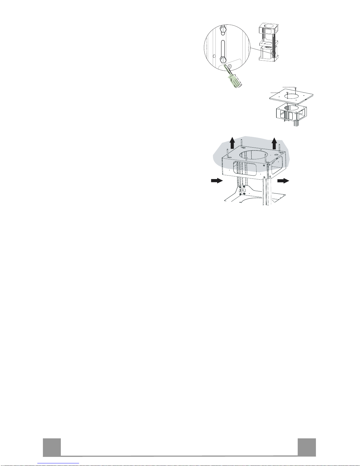
FIXING THE FRAME
If you wish to adjust the height of th e frame, proceed
as follows:
• Unfasten the metric screws joining the two columns,
located at the sid es of the frame.
• Adjust the frame to the height re
quired, then
replace all the screws removed as above.
• Fix the Fixing Part of the Upper Chimney 26 to the
hanging kit using the 2 screws 12w (M3 x 8).
• Lift up the frame, fit the frame slots onto the screws
up to the slot end positions.
• Tighten the two screws and fasten the other two
screws provided; before locking the screws com-
pletely, it is possible to adjust the frame by turning it,
making sure that the screws do not come out of their
housing in the adjustment slot.
• It is now possible to place and tighten the 4 safety
screws, Proceed as foll ows:
• drill the ceiling with a 10 mm ø bit taking as refer-
ence the holes of the side parts of the upper chimney fixing part.
• insert the 4 dowels (provided).
• insert the washers (provided) to the screws and
tighten the screws
• The Frame must be securely fastened so as to suppo rt
both the weight of the Hood and the stress caused by
occasional axial pressure against the fitted Appliance. After fixing, make sure that the base is stable
even when the Frame is subjected to lateral stress.
• If the Ceiling is not strong enough in the area where
the hood is to be fixed, the Installer must strengthen
the area using suitable plates and counterplates anchored to resistant structures.
2
2
1
1
12w
26
Page 12
EN
112
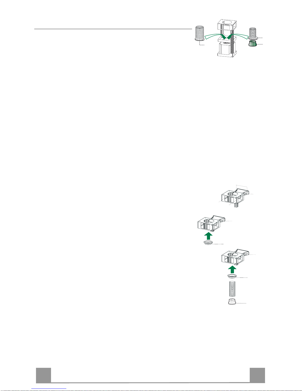
Ducted version air exhaust system Connection
When installing the ducted version, connect the hood to the
chimney using either a flexible or rigid pipe ø 150 or 120 mm,
the choice of which is left to the installer.
• To install a ø 120 mm air exhaust connection, insert the reducer flange 9 on the hood body outlet.
• Fix the pipe using the pipe clamps 25 provided.
• Remove any activated charcoal filters.
9
ø 150
ø 120
25
25
RECIRCULATION VERSION AIR OUTLET
• Insert the reducer flange 9 on the air outlet of the extractor.
• Attach the adhesive Novastik gasket 13 to the air outlet connection 15 and fix this to the upper frame using the 2 knobs 24.
• Fix the air outlet conn ection exten si on p iece 14 to the air outlet
connection 15.
• Connect the hood air outlet to the flange in the lower part of
the junction using a rigid or flexible ø 120 tube (by installer’s
choice).
14
15
24
15
14
15
9
Page 13
EN
113
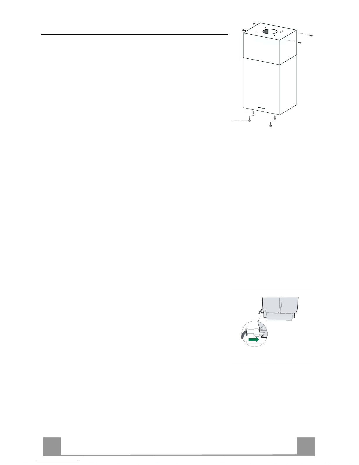
Flue assembly - Mounting the hood body
• Insert the upper duct and fix it on the top of the upper duct
connection using the 12c screws (2.9 x 9.5) supplied with the
appliance.
Recirculation version
• It is necess ary to make sure that t he air o utlet conn ection 15 is
placed correctly so that the air outlet grid in it correspond s to
that of the chimney.
• If the grids of the two parts are not corresponding to each
other, it will be necessary to remove the chimney and to adjust
the position of the air outlet connection 15, and at last to assembly the parts again by following the earlier indications.
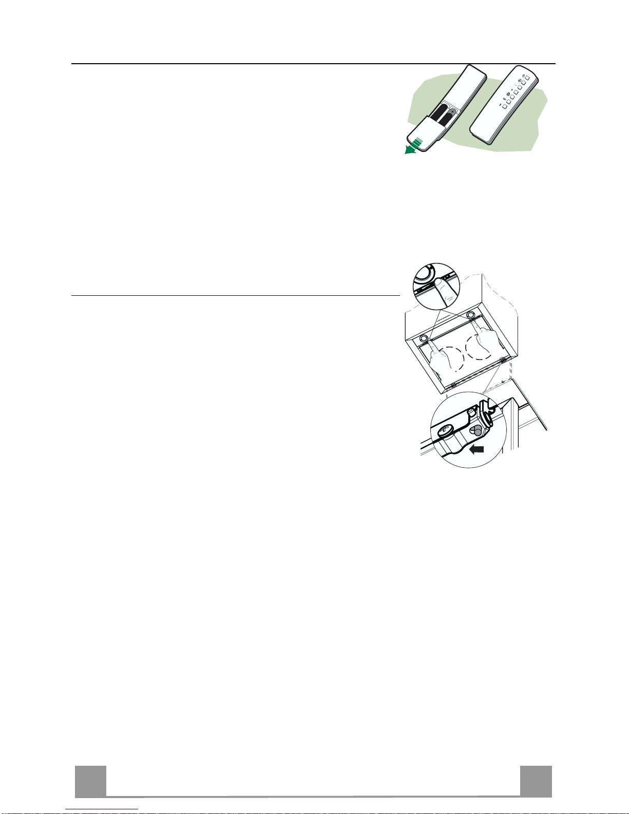
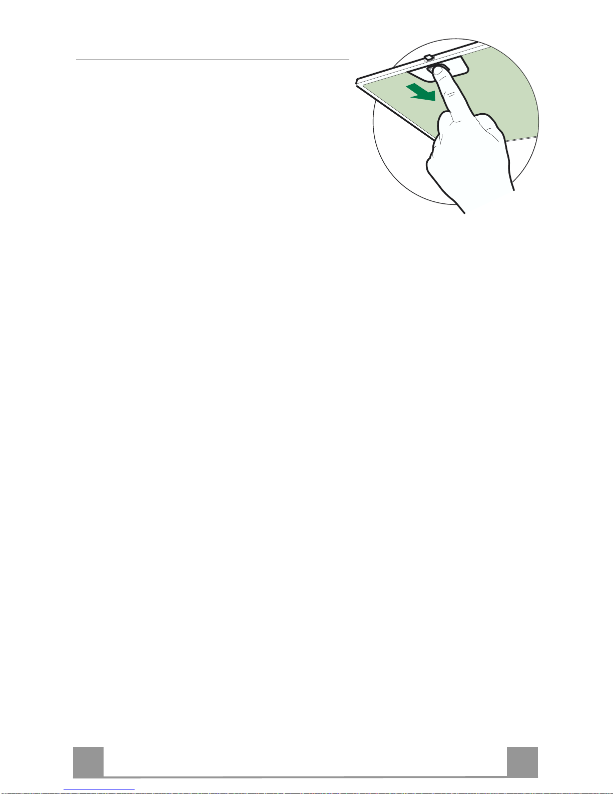
Before fixing the hood body to the frame:
• Open the suction panel by turning the specific knob.
• Disconnect the panel from the hood canopy by sliding the fixing pin lever.
• Remove the grease filters from the hood body.
• Remove any activated charcoal filters.
• From below, use the 4 screws 12f (M6 x 10) provided to fix the
hood body to the frame.
12c
12f
ELECTRICAL CONNECTION
• Connect the Hood to the mains power supply, inserting a twopole cut-out switch with contact aperture of at least 3 mm
along the line.
• Pull the Comfort Panel to open it, ensure that the supply cable
connector is properly inserted into the Suction device socket
• Join the connectors.
• Install the odour filter and the charcoal filter in case the hood is
to be used in recycling version.
• Install the grease filter again, and successively the suction
panel.
Page 14
EN
114
USE
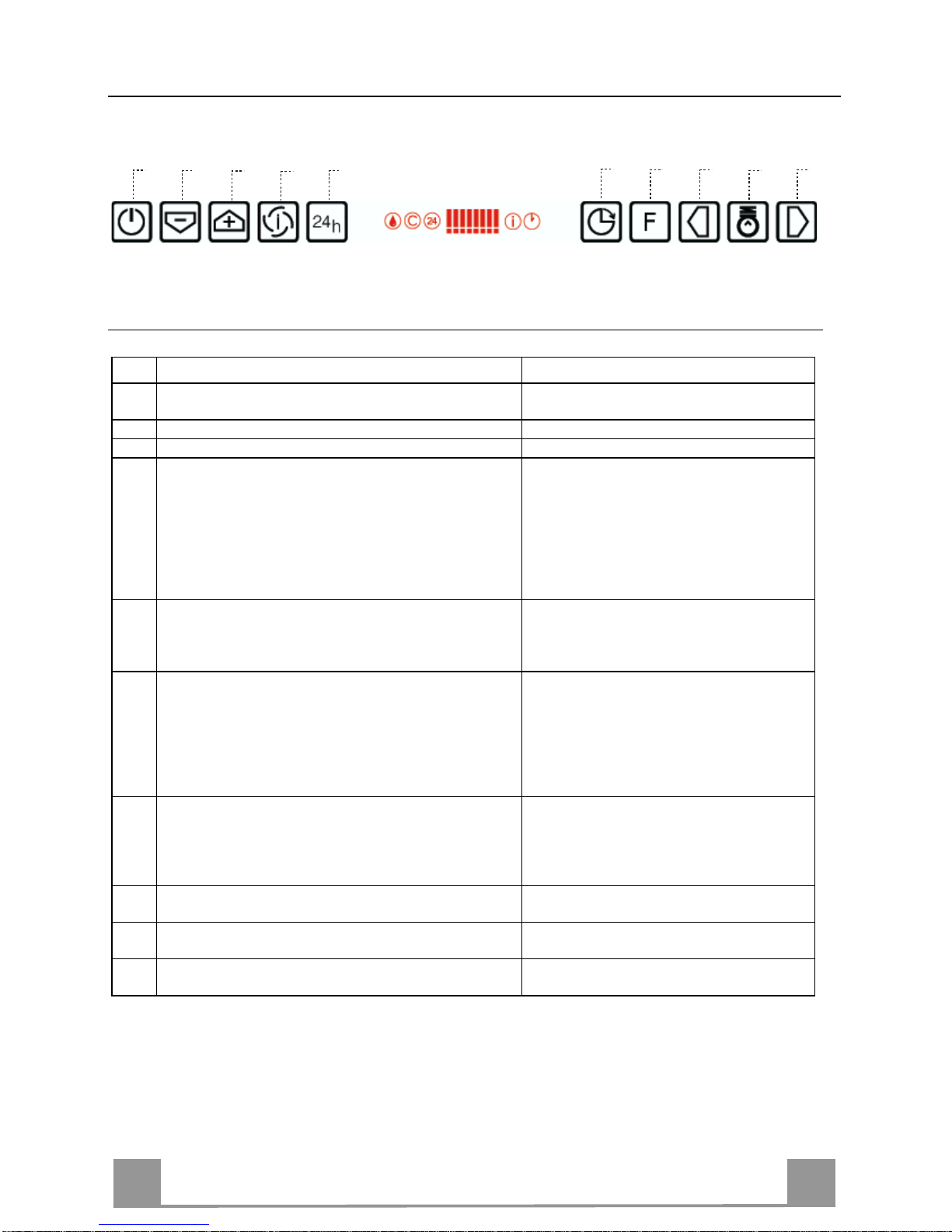
Control board
Key Function Display
A Switches the extractor motor on and off at t
he latest
selected speed
Indicates the selected speed.
B Decreases the suct ion speed. The numb er of lit LEDS decreases.
C Inc reases the suction speed. The number of lit LEDS increases.
D By pressing this key it is possible to start the inten-
sive speed from any previously selected speed except the Delay-function and 24H-function. This
speed has been timed at 10 minutes. After that time
the system activates automatically the latest selected
speed. This function is suitable for cooking conditions when vapours and smells are at the utmost emission.
I flashes and the LEDS are all lit.
By pressing the key the function is
stopped.
E By pressing this key it is possible to set up the motor
to a suction speed at 100 m
3
/h .
24 appears a nd the LEDS extinguish one
by one.
By pressing the key the function is
stopped
F By pressing this key it is possible to set the delayed
shutdown of the motor and the lighting to 30 minutes. This function is suitable for a complete elimination of resi dual cookin g odours. Fu nctionin g only
when the mot or is on(n ot du ring th e 24H-fu nc tion or
intensive function). By pressing the key the function
is stopped
A flashing clock-symbol appears.
By pressing the key the function is
stopped
G By pressing this key for about 2 seconds it is possi-
ble to reset the filter saturation alarm
After 100 working hours a drop-symbol
appears. Metal grease filters have to be
washed.
After 200 working hours C appears.
Charcoal filters have to replaced.
H By pressing this key the intensity of the lighting
system can be decreased.
I Switches on/ off th e lightin g system at th e maximu m
intensity.
L By pressing this key the intensity of the lighting
system can be increased.
Keyboard lock: it is possible to jam the ke yboard when, for examp le, cleaning the gl ass. The
motor and lights are switched off.
By pressing the F-key (Delay) for about 5 seconds the keyboard block can be activated or deactivated. This function is confirmed by a Beep and by moving motor LEDS on display.
B
A
D
C
E
G
F
I
H
L
Page 15
EN
115
MAINTENANCE
REMOTE CONTROL (OPTIONAL)
The appliance can be controlled using a remote control powered
by a 1.5 V carbon-zinc alkaline batteries of the standard LR03AAA type.
• Do not place the remote control near to heat sources.
• Used batteries must be disposed of in the proper manner.
Cleaning the Comfort Panels
• Pull the Comfort Panel to open it.
• Disconnect the panel from the hood canopy by sliding the fixing pin lever.
• The comfort panel must never be washed in a dishwasher.
• Clean the outside using a damp cloth and neutral liquid detergent.
• Clean the inside as well using a damp cloth and neutral detergent; do not use wet cloths or sponges, or jets of water; do not
use abrasive substances.
• When the above operation has been completed, hook the panel
back to the hood canopy and close it by turning the knob in the
opposite direction .
Page 16
EN
116
Metal grease filters
Metal filters can be washed also in a dish machine.
They need to be wash ed every ti me a drop-symbol appears in the disp lay or at l east ev ery two months. In case of very frequent use these have to be washed even
more often.
Alarm reset
• Press the G-key for at least 2 seconds.
Cleaning
• Open the comfort panel.
• Remove the filters one by one by pushing them
backwards and pulling them down contemporaneously.
• Wash the filters. Pay attention not to bend them.
Make sure that filters are completely dry before putting them into their seat. (a possible modification of
the filter surface doesn’t influence its efficiency).
• Place the filters again into their seats and make sure
that the handle of the filter remains outside.
• Close the comfort panel.
Page 17
EN
117
Charcoal filter (recycling version)
This filter cannot be washed or regenerated. It must be replaced when the C appears on the
display or at least once every 4 months. The filter saturation alarm has to be activated already
before.
Activation of the alar m signal
• In the recycling version hoods the filter saturation alarm must be activated during the installation or later.
• Switch off the hood and the lights.
• Press the E-key for about 5 seconds until the last two segments of the motor LEDS are lit on
the display.
• By releasing the E-key the clock icon starts to flash.
• Within 3 seconds press the D-key to activate/deactivate charco al filter saturation alarm.
• C-symbol lit - charcoal filter saturation alarm ACTIVATED.
• C-symbol unlit - charcoal filter saturation alarm DEACTIVATED.
SUBSTITUTION OF THE CHARCOAL FILTER
Alarm reset
• Switch off the motor and the lighting system.
• Press the G-key for at least 2 seconds.
Substitution of the filter
• Open the confort panel.
• Remove the metal grease filters.
• Remove the charcoal filter as indicated in the picture.
• Place the filter again into its seat.
• Place again the metal grease filters into their place.
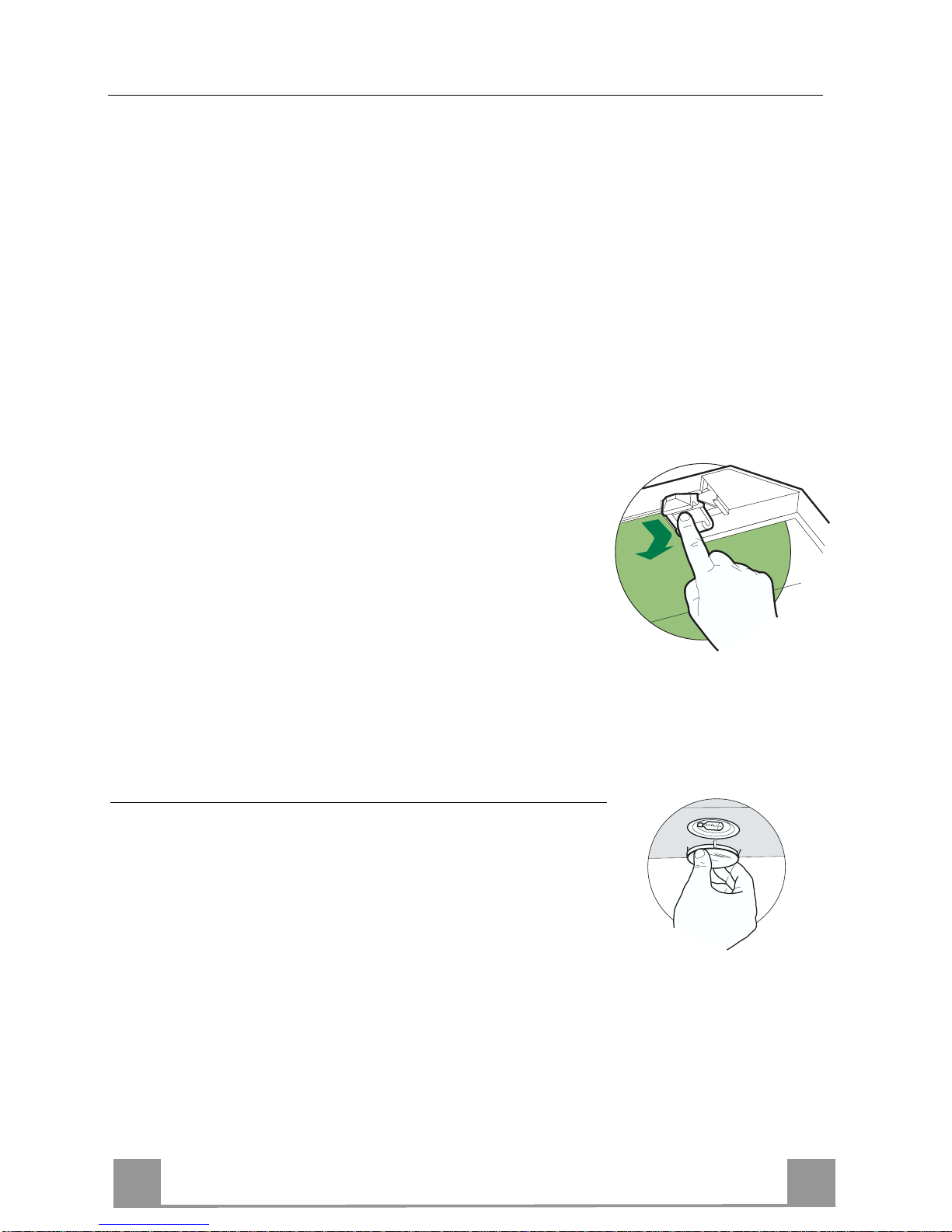
Lighting
LIGHT REPLACEMENT
20 W halogen light.
• Remove the snap-on lamp cover by levering it from under the
metal ring, supporting it with one hand.
• Remove the halogen lamp from the lamp holder by pulling
gently.
• Replace the lamp with a new one of the same type, making
sure that you insert the two pins properly into the housings on
the lamp holder.
• Replace the snap-on lamp cover.
Page 18

IT 118
CONSIGLI E SUGGERIMENTI
Questo libretto di istruzioni per l'uso è previsto per più versioni dell'apparecchio.
Possibile che siano descritti singoli particolari della dotazione, che non riguardano il
Vostro apparecchio.
INSTALLAZIONE
• Il produtto re declina qualsiasi re sponsabilità per dann i dovuti ad installa zione non
corretta o non conforme alle regole dell’arte.
• La distanza minima di sicurezza tra il Piano di cottura e la Cappa deve essere di
650 mm.
• Verificare che la tensione di rete corrisponda a quella riportata nella targhetta posta
all’interno della Cappa.
• Per Apparecchi in Classe Ia accertarsi che l’impianto elettrico domestico ga rantis ca
un corretto sc ar ico a terra.
• Collegare la Cappa all’uscita dell’aria aspirata con tubazione di diametro pari o
superiore a 12 0 mm. Il percorso della tubazione deve essere il più breve possibi le.
• Non collegare la Cappa a condotti di scarico dei fumi prodotti da combustione (caldaie, caminetti, ecc.).
• Nel caso in cui nella stanza vengano utilizzati sia la Cappa che apparecchi non
azionati da energia elettrica (ad esempio apparecchi utilizzatori di gas), si deve
provvedere ad una aerazione sufficiente dell’ambiente. Se la cucina ne fosse
sprovvista, praticare un’apertura che comunichi con l’esterno, per garantire il richiamo d’aria pulita.
USO
• La Cappa è stata progettata esclusivamente per uso domestico, per abbattere gli
odori della cucina.
• Non fare mai uso i mproprio dell a Cappa.
• Non lasciare fiamme libere a fort e intensità sotto la Cappa in funzione.
• Regolare sempre le fiamme in modo da evitare una evidente fuoriuscita laterale
delle stesse ri spetto al fondo delle pentole.
• Controllare le friggitrici durante l’uso: l’olio surriscaldato potrebbe infiammarsi.
• Non preparare alimenti flambè sot to la cappa da cu cina; pericolo d'incendio.
• Questo apparecchio non deve essere utilizzato da persone (bambini inclusi) con
ridotte capacità psichiche, sensoriali o mentali, oppure da persone senza esperienza e conoscenza, a meno che non siano controllati o istruiti all’uso dell’apparecchio
da persone responsabili della loro sicurezza.
• I bambini devono essere supervisionati per assicurarsi che non giochino con
l’apparecchio.
MANUTENZIONE
• Prima di procedere a qualsiasi operazione di manutenzione, disinserire la Cappa
togliendo la spina elettrica o spegnendo l’interruttore generale.
• Effettuare u na sc rup o los a e tempestiva m anu te nz io ne dei Filtri secondo gli intervalli
consigliati.
• Per la pulizia delle superfici de lla Cappa è sufficien te utilizzare un panno u mido e
detersivo li quido neutro.
Il simbolo sul prodotto o sulla confezione indica che il prodotto non deve essere considerato
come un normale rifiuto domestico, ma deve essere portato nel punto di raccolta appropriato per il
riciclaggio di apparecchiature elettriche ed elettroniche. Provvedendo a smaltire questo prodotto in
modo appropriato, si contribuisce a evitare potenziali conseguenze negative per l’ambiente e per la
salute, che potrebbero derivare da uno smaltimento inadeguato del prodotto. Per informazioni più
dettagliate sul riciclaggio di questo prodotto, contattare l’ufficio comunale, il servizio locale di smaltimento rifiuti o il negozio in cui è stato acquistato il prodotto.
650 mm min.
Page 19
IT 119
CARATTERISTICHE
Ingombro
*
**
* Dimensioni per cappa in versione aspirante.
** Dimensioni per cappa in versione filtrante.
Page 20
IT 220
Componenti
Rif. Q.tà Componenti di Prodotto
1 1 Corpo Cappa completo di: Comandi, Luce,Gruppo
Ventilatore, Filtri, Camino Infer iore
2 1 Camino Superiore
7.1 1 Traliccio telesco pico completo di Aspir atore,formato da:
7.1a 1 Traliccio superiore
7.1b 1 Traliccio inferiore
9 1 Flangia di Riduzione ø 1 50-120 mm
13 1 Guarnizione Adesiva Novastik
14 1 Flangia per Raccordo Uscita Aria
15 1 Raccordo Uscita Aria
25 2 Fascette stringitubo
26 1 Attacco Camino Superiore
Rif. Q.tà Componenti di Installazione
11 4 Tasselli ø 10
12c 4 Viti 2,9 x 9,5
12f 4 Viti M6 x 10
12g 4 Viti M6 x 80
12h 4 Viti 5,2 x 70
12w 2 Viti M3 x 8
21 1 Dima di foratura
22 4 Rondelle øi 6,4
23 4 Dadi M6
24 2 Pomelli fissaggio R accordo Uscita Aria
Q.tà Documentazione
1 Libretto Istruzioni
23
22
12h
11
15
24
1
12f
2
7.1
7.1b
7.1a
21
12g
12w
14
26
12c
13
9
25
Page 21

IT 221
INSTALLAZIONE
Foratura Soffitto/Mensola e Fissaggio Traliccio
FORATURA SOFFITTO/MENSOLA
• Con l’ausilio di un Filo a piombo riportare sul Soffitto/Mensola di supporto il centro del
Piano di Cottura.
• Appoggiare al Soffitto/Mensola la Dima di Foratura 21 in dotazione, facendo coincidere il
suo centro al centro proiettato e allineando gli assi della Dima agli assi del Piano di Cottura.
• Segnare i centri dei Fori della Dima.
• Forare i punti seguenti:
• Soffitto in Calcestruzzo massiccio: secondo Tasselli per Calcestruzzo impiegati.
• Soffitto in Laterizio a camera d’aria, con spessore resistente di 20 mm: ø 10 mm (inserire
subito i Tasselli 11 in do ta z ione ) .
• Soffitto in Travatura di Legno: secondo Viti per Legno impiegate.
• Mensola in Legno: ø 7 mm.
• Passaggio del Cavo elettrico di Alimentazione: ø 10 mm.
• Uscita Aria (Versione Aspirante): secondo diametro del collegamento alla Tubazione di
Evacuazione Esterna.
• Avvitare, incrociandole e lasciando 4-5 mm dal soffitto, due viti:
• per Calcestruzzo massiccio, Tasselli per Calcestruzzo, non in dotazione.
• per Laterizio a ca mera d’aria, co n spesso re resistente d i 20 mm circa, V iti 12h, in dotazio-
ne.
• per Travatura di legno, Viti per legno, non in dotazione.
• per Mensola in Legno, viti 12g con Rondelle 22 e Dadi 23, in dotazione.
Page 22

IT 222
FISSAGGIO TRALICCIO
Nel caso in cui si vogl ia regolare l’altezza del t r aliccio :
• Svitare le viti che uniscono le due colonne.
• Regol are il tral iccio all ’altezza desi derata e riavvit are
le viti.
• Unire l’Attacco Camino Superiore 26 al traliccio superiore tramite le 2 Viti 12w (M3 x 8).
• Sollevare il traliccio, incastrare le asole sulle viti e
scorrere fino a battuta. A questo punto il traliccio si
regge da solo
• Stringere le due viti e avvitare le altre due in dotazione sulla piastra superiore;
Prima di serrare definitivamente le viti è possibile
effettuare delle regolazioni spostando il traliccio,facendo attenzione che le viti non escano dalla
sede dell’asola di regolazione.
• Ora è po ssibile avvitare 4 viti di sicurezza,per farlo,
procedere come ind i cato:
• forare con una punta ø 10 il soffitto utilizzando i
fori posti sui lati dell’at t acco camino superiore.
• Inserire 4 tasselli in dotazione
• Inserire le Rondelle in dotazione nelle viti e serrare.
• Il fissaggio del Traliccio deve essere sicuro in relazione sia al peso della Cappa sia alle sollecitazioni
causate da occasionali spinte laterali all’Apparecchio
montato. A fissaggio avvenuto verificare quindi che
la base sia stab ile anche se il Tral iccio è solleci tato a
flessione.
• In tutti i casi in cui il Soffitto non fosse sufficientemente robusto sul punto di sospensione, l’Installatore
dovrà provvedere a irrobustirlo con opportune piastre
e contropiastre ancorate a parti strutturalmente resistenti.
2
2
1
1
12w
26
Page 23

IT 223
Connessione Uscita aria Versione Aspirante
Per installazione in Versione Aspirante collegare la Cappa alla
tubazione di uscita per mezzo di un tubo rigido o flessibile di
ø 150 o 120 mm, la cui scelta è lasciata all’installatore.
• Per collegamento con tubo ø 120 mm, inserire la Flangia di
riduzione 9 sull’Uscita del Corpo Cappa.
• Fissare il tubo con adeguate fascette stringitubo 25 in dotazione.
• Rimuovere eventuali filtri al carbone attivo.
9
ø 150
ø 120
25
25
USCITA ARIA VERSIONE FILTRANTE
• Inserire la Flangia di riduzione 9 sull’uscita dell’Aspiratore.
• Attaccare la Guarnizione Adesiva Novastik 13 sul Raccordo
Uscita Aria 15 e fissarlo al trali ccio superiore tramite i 2 Po melli 24.
• Attac care la Flangia Raccordo Uscit a Aria 14 al Raccordo Uscita Aria 15.
• Collegare l’uscita aria della cappa con la flangia posta sotto al
raccordo per mezzo di un tubo rigido o flessibile ø 120mm, la
cui scelta è lasciata all’installatore.
14
15
24
15
14
15
9
Page 24

IT 224
Montaggio Camino e Fissaggio Corpo Cappa
• Inserire il Camino superiore e fissarlo nella parte superiore
all’Attacco Camino Superiore con le Viti 12c (2,9 x 9,5) in dotazione.
Versione filtrante
• Assicurarsi che il Raccordo Uscita Aria 15 sia in corrispondenza della Grigliatura del Camino.
• Se così non fosse, rimuovere il camino e aggiustare la posizione del Raccordo Uscit a Aria 15; rimontare quindi i particolari
come prima descritto.
Prima di fissare il Corpo Cappa al Traliccio:
• Aprire il pannello aspirante tirandolo.
• Sganciare il pannello dal corpo cappa facendo scorrere
l’apposita leva del perno di fissaggio.
• Togliere i Filtri antigrasso dal Corpo Cappa.
• Togliere eventuali Filtri Antiodore al Carbone attivo.
• Fissare quindi dal sotto, con 4 viti 12f in dotazione, il Corpo
Cappa al Traliccio predisposto.
12c
12f
CONNESSIONE ELETTRICA
• Collegare la Cappa all’Alimentazione di Rete interponendo un
Interruttore bipolare con apertura dei contatti di almeno 3 mm.
• Aprire il Pannello Aspirante e i filtri antigrasso, assicurarsi che
il connettore del Cavo d i alimentazione sia corret tamente inserito nella presa dell’Aspiratore
• Effettuare i collegamenti dei Connettori
• Per la Versione Filtrante montare il Filtro Antiodore al Carbone attivo.
• Rimontare i Filtri Antigrasso e il Pannello Aspirante.
Page 25

IT 225
USO
Quadro comandi
Tasto Funzione Display
A Accende e spegne il motore di aspirazione
all’ultima velocità utilizzata.
Visual izza la velocità impostata.
B Decrementa la velocit à di esercizio. Diminui scono i segmen ti accesi.
C Incr ementa la velocità di esercizio. Aumentano i segmenti accesi.
D Attiva la velocità intensiva da qualsiasi velo-
cità ad ecc ezione del Dela y e del 24H, ta le velocità è temporizzata a 10 minuti, al termine
del tempo il sistema ritorna alla velocità precedentemente impostata. Adatta a fronteggiare le
massime emissioni di fumi di cottura.
Lampeggia I e i segmenti sul Display sono tutti
accesi.
Si disattiva premendo il Tasto.
E Attiva il motore ad una velocità che consente
un’aspira zione di 100 m
3
/h per 10 minuti ogni
ora, terminati il motore si ferma.
Visualizza 24 e i segmenti sul Display da tutti
accesi si spengono uno alla volta cicli camente.
Si disattiva premendo il Tasto.
F Attiva lo spegnimento automatico ritardato di
30’. Adatto per completare l’eliminazione di
odori residui. Attivabile solo a motore acceso
ad una Velocità diversa da 24H e Intensiva, si
disattiva premendo il tasto o spegnendo il motore.
Visualizza il simb olo di un Orologio che lampeggia.
Si disattiva premendo il Tasto.
G Effettua il Reset dell’allarm e satura zione Filtri
premendo il Tasto per circa 2 Secondi.
Dopo 100 ore di Funzionamento Visualizza il
simbolo Goccia per segnalare la saturazione
dei Filtri Metallici.
Dopo 200 ore di Funzionamento Visualizza C
per segnala re la sa tur azion e dei Filtri al Ca rbone Attivo.
H Decrementa l’intensità di Illuminazione ad
ogni pres sione del Tasto in modo ciclic o.
I Accende e spegne l’impianto di illuminazione
alla massima intensità.
L Increment a l’int ensit à di Illumi nazi one ad ogn i
pressione del Tasto in modo ciclico.
Comando Blocco Tastiera: è possibile bloccare la tastiera, ad esempio per effettuare l a pulizia
della superficie in Vetro, quando la Cappa ha il Motore e le Luci spente.
Premendo per circa 5 Secondi il tasto F (Delay) si può abilitare o disabilitare il Blocco Tastiera
che è sempre confermato con un Beep e un’animazione sulla barra motore del display.
B
A
D
C
E
G
F
I
H
L
Page 26

IT 226
MANUTENZIONE
TELECOMANDO (OPZIONALE)
Questo apparecchio può essere comandato per mezzo di un telecomando, alimentato con pile alcaline zinco-carbone da 1,5 V del
tipo standard LR03-AAA.
• Non riporre il telecomando in prossimità di fonti di calore.
• Non disperdere le pile nell’ambiente, depositarle negli appositi
contenitori.
Pulizia dei Confort Panel
• Aprire il Confort Panel tirandolo.
• Sganciare il pannello dal corpo cappa facendo scorrere
l’apposita leva del perno di fissaggio.
• Il confort panel non va assolutamente lavato in lavastoviglie.
• Pulirlo esternamente con un panno umido e detersivo liquido
neutro.
• Pulirlo anche internamente utilizzando un panno umido e detergente neutro; non utilizzare panni o spugne bagnate, n é getti
d’acqua; non utilizzare sostanze abrasive.
• Ad operazione ultimata riagganciare il pannello al corpo cappa
e richiuderlo.
.
Page 27

IT 227
Filtri antigrasso metallici
Sono lavabili anche in lavastoviglie, e necessitano di
essere lavati quando sul display appare il simbolo Goc-
cia o almeno ogni 2 mesi circa di utilizzo o più frequentemente, per un uso particolarmente intenso.
Reset del segnale di allarme
• Premere il tasto G per almeno 2 Secondi.
Pulizia Filtri
• Aprire il comfort panel.
• Togliere i Filtri uno alla volta, spingendoli verso la
parte posteriore del gruppo e tirando contemporaneamente verso il basso.
• Lavare i Filtri evitando di piegarli, e lasciarli asciugare prima di rimontarli. (Un’eventuale cambiamento
del colore della superficie del filtro, che potrebbe verificarsi nel tempo, non pregiudica assolutamente
l’efficienza dello stesso.)
• Rimontarli facendo attenzione a mantenere la maniglia verso la parte visibile esterna.
• Richiudere il comfort panel.
Page 28

IT 228
Filtri antiodore al Carbone attivo (Versione Filtrante)
Non è lavabile e non è rigenerabile, va sostituito quando sul display appare il simbolo C o almeno ogni 4 mesi. La segnalazione di Allarme va preventivamente attivata.
Attivazione del segnale di all arme
• Nelle Cappe in Versione Filtrante, la segnalazione di Allarme saturazione Filtri va attivata al
momento dell’installazione o successivamente.
• Spegnere le Luci e il Motore di asp irazione.
• P remere il tasto E per circa 5 Sec . fino all’accensio ne degli ultimi due segmenti e di tu tta la
linea puntinata della barra Motore sul Display.
• Rilasciare il tasto E, l’icona “Orologio” inizia a lampeggiare.
• Entro 3 secondi premere il Tasto D per abilitazione / disabilitazione Filtri C.A.
• Accensione del simbolo C Allarme saturazione Filtro C.A. ATTIVATO
• Spegnimento del simbolo C Allarme saturazione Filtro C.A. DISATTIVATO
SOSTITUZIONE FILTRO ANTIODORE AL CARBONE ATTIVO
Reset del segnale di allarme
• Spegnere le Luci e il Motore di asp irazione.
• Premere il tasto G per almeno 2 Secondi.
Sostituzione Filtro
• Aprire il comfort panel.
• Togliere i Filtri antigrasso metallici.
• Rimuovere il Filtro antiodore al Carbone attivo saturo, come
indicato in figura.
• Montare il nuovo Filtro agganciandolo nella sua sede.
• Rimontare i Filtri antigrasso metallici.
Illuminazione
SOSTITUZIONE LAMPADE
Lampade alogene d a 20 W
• Togliere il bloccavetro metallico a pressione facendo leva sotto
la ghiera, sostenendolo con una man o.
• Estrarre la lampadina alogena d al portalampada.
• Sostituirla con una nuova lampadina di uguali caratteristiche,
facendo attenzione ad inserire correttamente i due spinotti nella
sede del portalampade.
• Rimontare il bloccavetro a pressione.
Page 29

FR
229
CONSEILS ET SUGGESTIONS
La présente notice d'emploi vaut pour plusieurs versions de l'appareil. Elle peut contenir des
descriptions d 'accessoires ne figurant pas dans votre appareil.
INSTALLATION
• Le fabricant dé c line toute responsabilité en cas de dommage dû à une installation non correcte ou non conforme aux règles de l’a rt.
• L a dist a nc e mini m ale de s éc urit é entr e l e pl an de c uiss on et la hot t e doi t êtr e d e 6 50 mm au
moins.
• Vérifier que la tensio n du s ecteur correspond à la valeur qui figure sur la plaquette apposée à
l’intérieur de la hotte.
• Pour les Appareils appartenant à la Ière Classe, veiller à ce que la mise à la terre de
l’installation élect rique do mestique ait été effe ctuée confo rmément aux nor mes en vigueur.
• Connecter la hotte à la sort ie d’air aspiré à l’aide d’une tu yauterie d’un diamè tre égal ou supérieur à 120 mm. Le parcours de la tuyauterie doit être le plus court possible.
• Eviter de connecter la hotte à des conduites d’évacuation de fumées issues d’une combustion tel que (Chaudière, ch eminée, etc…).
• Si vous utilisez des appareils qui ne fonctionnent pas à l’électricité dans la pièce ou est installée la hotte (par exemple: des appareils fonctionnant au gaz), vous devez prévoir une aération suffisante du milieu. Si la cuisine en est dépourvue, pratiquez une ouverture qui communique avec l’extér ieur pour garantir l’infiltration de l’air pur.
UTILISATION
• La hotte a été conç ue exclusivement pour l’ usage domestiq ue, dans le but d’ éliminer les
odeurs de la cuisine.
• Ne jamais utiliser abusivement la hotte.
• Ne pas laisser les flammes libres à forte intensité quand la hotte est en service.
• To ujours régl er les flammes de manière à éviter tout e sortie latér ale de ces d ernières par
rapport au f ond des marmites.
• Contrôler les friteuses lors de l’utilisation car l’huile surchauffée pou rrait s’enf lammer.
• Ne pas préparer d’aliments flambé s sous la hotte de cuisine : risque d’in cendie
• Cet appareil ne doit pas être utilisé par des personnes (y compris les enfants) ayant des
capacit és psychi ques, s ensori elles o u mental es rédui tes, ni p ar des p ersonne s n’ayan t pas
l’expérience et la connaissance de ce type d’appareils, à moins d'être sous le contrôle et la
formation de personnes respon sables de leur sécurité.
• Les enfants doivent être surveillés pour s'assurer qu'ils ne jouen t pas avec l'appa reil.
ENTRETIEN
• Avant d e procé der à tout e opérati on d’e ntretie n, retirer la hotte en retiran t la fich e ou en actionnant l’interrupt eu r général.
• Effectuer un entretien scrupuleux et en temps dû des Filtres, à la cadence conseillée.
• Pour le nettoyage des surfaces de la hotte, il suffit d’utiliser un chiffon humide et détersif
liquide neutre.
Le symbole sur le produit ou son emballage indique que ce produit ne peut être traité comme déchet
ménager. Il doit plutôt être remis au point de ramassage concerné, se chargeant du recyclage du matériel
électrique et électronique. En vous assurant que ce produit est éliminé correctement, vous favorisez la
prévention des conséquences négatives pour l’environnement et la santé humaine qui, sinon, seraient le
résultat d’un traitement inapproprié des déchets de ce produit. Pour obtenir plus de détails sur le recyclage
de ce produit, veuillez prendre contact avec le bureau municipal de votre région, votre service d’élimination
des déchets ménagers ou le magasin où vous avez a cheté le produit.
650 mm min.
Page 30

FR
330
CARACTERISTIQUES
Encombrement
*
**
* Dimensions pour hotte en version aspirante.
** Dimensions pour hotte en version filtrante.
Page 31

FR
331
Composants
Réf. Q.té Composants de Produit
1 1 Corps Hotte équipé de: Comandes, Lumière, Filtres
2 1 Cheminée Supérieure
7.1 1 Treillis télescopique avec Aspirateur, formé par:
7.1a 1 Treillis supérieur
7.1b 1 Treillis inférieur
9 1 Flasque de Réducti on ø 150-1 2 0 mm
13 1 Joint
14 1 Rallonge Sortie Air Corps Hotte
15 1 Raccord Sortie Air
25 2 Colliers de serrage serre-tube
26 1 Fixation de la Cheminée Supérieur
Réf. Q.té Composants pour l’installation
11 4 Chevilles ø 10
12c 4 Vis 2,9 x 9,5
12f 4 Vis M6 x 15
12g 4 Vis M6 x 80
12h 4 Vis 5,2 x 70
12w 2 Vis M3 x 8
21 1 Gabarit de perçage
22 4 Rondelles øi 6,4
23 4 Écrous M6
24 2 Pommeaux de fixation Raccord Sortie de l’Ai r
Q.té Documentation
1 Manuel d’instructions
23
22
12h
11
15
24
1
12f
2
7.1
7.1b
7.1a
21
12g
12w
14
26
12c
13
9
25
Page 32

FR
332
INSTALLATION
Perçage Plafond/Étagère et Fixation Treillis
PERÇAGE PLAFOND/ETAGERE
• À l’aide d’un Fil à plomb, reporter sur le Plafond/Étagère de support le centre du Plan de
Cuisson.
• Poser contre le Plafond/Étagère le Gabarit de Perçage 21 fourni avec l’appareil, en faisant
coïncider son centre avec le centre projeté et en alignant les axes du Gabarit avec les axes du
Plan de Cuisson.
• Marquer les centres des Trous du Gabarit.
• Percer les trous qui ont été marqués:
• Plafond en Béton massif: en fonction des Goujons pour Béton utilisés.
• P lafond en Briques avec chambre à air, avec ép aisseur résist ante de 2 0 mm: ø 10 mm (in-
sérer immédiatement les Chevilles 11 fournies avec l’appareil).
• Plafond en Poutrage en Bois: en fonction des Vis à Bois utilisées.
• Étagère en Bois: ø 7 mm.
• Passage du Câble électrique d’Alimentation: ø 10 mm.
• Sortie Air (Version Aspirante): en fonction du diamètre de la connexion avec les Tuyaux
d’Évacuation Externe.
• Visser deux vis en les croisant et en laissant 4-5 mm. de distance par rapport au plafond:
• pour le Béton massif, des Goujons pour Béton, non fournis avec l’appareil.
• p our Briques percées, ayant une épaisseur résistan te de 20 mm. environ, utiliser les Vis
12h, fournies avec l'appareil .
• pour le Poutrage en bois, 4 Vis à bois, non fournies avec l’appareil.
• pour l’Étagère en Bois, 4 Vis 12g avec Rondelles 22 et Écrous 23, fournis avec l’appareil.
Page 33

FR
333
FIXATION DU TR EILLIS
Si l’on souhaite régler la hauteur du treillis, effectuer
les opérations suivantes:
• Dévisser les vis métriques qui unissent les deux colonnes, qui se trouvent sur les côtés du treillis.
• Régler la hauteur souhaitée du treillis et revisser les
vis qui ont été précédemment retirées.
• Fixer la Fixation de la Cheminée Supérieure 26 au
trellis à l’aide des 2 Vis 12w (M3 x 8).
• Soulever le treillis, encastrer les oeillets sur les vis et
faire coulisser jusqu’à la butée;
• Serrer les deux vis et visser les d eux autres vis fournies avec l’appareil; avant de serrer défini-tivement
les vis, il est possible d’effectuer des réglages en
tournant le treillis, en veillant à ce que les vis ne sortent pas du logement de l’oeillet de réglage.
• Maintenant il est possible de visser les 4 vis de sécurité; pour effectuer cette opération, suivre les instructions suivantes :
• percer le plafond,avec une mèche de ø 10, en uti-
lisant les trous qui se trouvent sur les côtés u dispositif de fixation de la cheminée supérieure.
• Insérer les 4 chevilles fournies avec l’appareil.
• Insérer les Rondelles fournies avec l’appareil dans
les vis, puis serrer.
• La fixation du Treillis doit être effectuée de façon
sûre, en fonction du poids de la Hotte et des contraintes provoquées par des poussées latérales occasionnelles de l’Appareil monté. Après avoir effectué la
fixation, vérifier que la base soit stable, même si le
Treillis est soumis à des contraintes de flexion.
• Dans toutes les éventualités selon lesquelles le Plafond ne serait pas suffisamment robuste en correspondance du point de suspension, l’Installateur devra
se charger de le rendre plus solide avec des plaques
et contre-plaqu es appropriées, ancrées aux part ies résistantes, du point de vue st ru ct urel.
2
2
1
1
12w
26
Page 34

FR
334
SORTIE AIR VERSION ASPIRA NTE
En cas d’install ation en version aspirante, brancher la ho tte à la
tuyauterie de sortie via un tube rigide ou flexible de ø 150 ou 120
mm, au choix de l’installateur.
• En cas de branchement avec un tube de ø120 mm, insérer le
flasque de réduction 9 sur la sortie du corps de la hotte.
• Fixer le tuyau à l’aide des Colliers de serrage serre-tube 25
fournis avec l’appareil.
• Retirer les éventuels filtres anti-odeur au charbon actif.
9
ø 150
ø 120
25
25
SORTIE AIR VERSION FILTRANTE
• Insérer la Flasque de raccord 9 sur la sortie de l’Aspirateur.
• Fixer la Garniture Adhésive Novastik 13 sur le Raccord Sortie
de l’Air 15 et fixer celle-ci au treillis supérieur, au moyen des 2
Pommeaux 24.
• Fixer la Flasque de Raccord Sortie de l’Air 14 au Raccord Sortie de l’Air 15.
• Joi ndre la sortie d’air de la hotte avec la br ide placée sous la
rallonge par un tuyau rigide ou flexible ø120 (le choix est de
l’installateur).
14
15
24
15
14
15
9
Page 35

FR
335
Montage de la Cheminée et Fixation du Corps de la
Hotte
• Enfiler le conduit supérieur dans la partie supérieure du raccord du conduit supérieur et le fixer au moyen des vis 12c (2,9
x 9,5) fournies avec l’appareil.
Version Filtrante
• S’assurer que le Raccord Sortie de l’Air 15 se trouve en
correspondance de la Grille de la Cheminée.
• Si tel n’est pas le cas, retirer la cheminée et ajuster la position
du Raccord Sortie de l’Air 15; ensuite, remonter les pièces
comme décrit précéd emment.
Avant de fixer le Corps de la Hotte au Treillis:
• Ouvrir le panneau aspirant, en tournant le bouton spécialement
prévu.
• Décrocher le panneau du corps de la hotte, en faisant coulisser le
levier du goujon de fixation spéc ialement prév u.
• Retirer les Filtres anti-graisse du Corps de la Hotte.
• Retirer les éventuels Filtres Anti-odeur au
• Ensuite, fixer par le bas, au moyen de 4 Vis 12f fournies avec
l’appareil, le Corps de la Hotte au Treillis prévu.
12c
12f
BRANCHEMENT ÉLECTRIQUE
• Brancher la Hotte au Réseau d’Alimentation, en interposant un
Interrupteur bipolaire avec ouverture des contacts de 3 mm. au
moins.
• Ouvrir le Comfort Panel, en tirant ce dernier s’assurer que le
connecteur du Câble d’alimentation soit inséré correctement
dans la prise de l’Aspirateur.
• Effectuer les connexions des connecteurs.
• Pour la Version Filtrante, monter le Filtre Anti-odeur aux
Charbons actifs.
• Re monter les filtres Anti-graisse puis, par la suite, le panneau
aspirant.
Page 36

FR
336
UTILISATION
Tableau des commandes
Touche Fonction Afficheur
A Allume et éteint le moteur d’aspiration à la der-
nière vitesse utilisée
La vitesse choisie s’affiche.
B La vitesse de service diminue. Les segments allumés diminuent.
C La vitesse de service augmente. Les segments allumés augmentent.
D Active la vitesse intensive à partir de n’importe
quelle vitesse, à l’exception des fonctions Retard
et 24H. Cette vitesse est programmée pour durer
10 minutes, après quoi le système retourne à la
vitesse ré glée au préala ble. Apte à fa ire face à une
quantité maximale de fumées de cuisson.
I clignote et les segments affichés sont
tous allumés.
Appuyer sur la touche pour désactiver.
E Active le moteur à une vitesse permettant une aspi-
ration de 100 m
3
/h pendant 10 minutes chaque
heure, puis le moteur s’arrête.
24 s’affich e et les segments affichés q ui
étaient tous allumés s’éteignent un à un
de manière cyclique.
Appuyer sur la touche pour désactiver.
F Active l’arrêt automatique retardé de 30 minutes.
Sert à éliminer complètement toute odeur résiduelle. S’active quand le moteur allumé à une
vitesse différente de 24H et Intensive ; appuyer sur
la touche ou éteindre le moteur pour désactiver
cette fonction.
Le symbole d’une horloge qui clignote
s’affiche.
Appuyer sur la touche pour désactiver.
G Rétablit l’alarme de saturation des filtres en ap-
puyant sur la touche pendant environ 2 secondes.
Le symbole Goutte s’affiche après 100
heures de service pour signaler la saturation des filtres métalliques.
C s’affiche après 200 heures de service
pour signaler la saturation des filtres au
charbon actif.
H L’intensité de l’éclairage diminue de façon cycli-
que chaque fois que l’on appuie sur la touche.
I Allume et éteint l’éclairage à int ensité maximale.
L L’intensité de l’éclairage augmente de façon cycli-
que chaque fois que l’on appuie sur la touche.
Commande de blocage du Clavier : il est possible de bloquer le clavier, par exemple pour effectuer le nettoyage des surfaces en verre quand le moteur et l’éclairage de la hotte sont
éteints.
Appuyer sur la touche F (Retard) pendant env. 5 secondes pour activer ou désactiver le blocage du clavier ; cette fonction est toujours confirmée par un bip sonore et une animation qui
s’affiche sur la barre du moteur.
B
A
D
C
E
G
F
I
H
L
Page 37

FR
337
ENTRETIEN
TELECOMMANDE (FOURNIE SUR DEMANDE)
Il est possible de commander cet appareil au moyen d’une télécommande, alimentée avec des piles alcalines zinc-charbon 1,5 V
du type standard LR03-AAA.
• Ne pas ranger la télécommande à proximité de sources de chaleur.
• Ne pas jeter les piles; il faut les déposer dans les récipients de
récolte spécialement prévus à cet effet.
Nettoyage des Confort Panel
• Ouvrir le Confort Panel, en tirant ce dernier.
• Décrocher le panneau du corps de la hotte, en faisant coulisser
le levier du goujon de fixation spécialement prévu.
• En aucun cas, le confort panel ne doit être lavé au lavevaisselle.
• Le nettoyer à l’extérieur à l’aide d’un chiffon humide et d’un
détergent liquide neutre.
• Le nettoyer également à l’intérieur, en utilisant un chiffon humide et un détergent neutre; ne pas utiliser des chiffons ou des
éponges mouillées, ni des jets d’eau; ne pas utiliser des substances abrasives.
• Lorsque l‘opération est achevée, accrocher à nouveau le panneau sur le corps de la hotte, puis le refermer, en tournant le
bouton dans le sens inverse par rapport à l’ouverture.
Page 38

FR
338
Filtres à graisse métalliques
Ils sont lavables même en lave-vaisselle et doivent être
lavés chaque fois que le symbole Goutte s’affiche ou
au moins tous les 2 mois environ, voire plus souvent, en
cas d’utilisation particulièrement intensive.
Rétablissement du signal d’alarme
• Appuyer sur la touche G pendant au moins 2 se-
condes.
Nettoyage des filtres
• Ouvrir le panneau Confort.
• Retirer les filtres, un à un, en les poussant vers
l’arrière du groupe tout en les tirant vers le bas.
• Laver les filtres en évitant de les plier, et les faire
sécher avant de les remonter. (Tout changement de
couleur sur la surface du filtre, susceptible de se
produire avec le temps, n e nuit en rien à l’efficacité
de ce dernier.)
• Remonter les filtres en faisant attention de tenir la
poignée vers la part ie externe visible.
• Refermer le panneau Confort.
Page 39

FR
339
Filtres anti-odeur au charbon actif (version filtrante)
Il ne peut être ni lavé ni récupéré, il faut le changer quand le symbole C s’affiche ou au moins
tous les 4 mois. Il faut tout d’abord activer le signal d’alarme.
Activation du signal d’alarme
• Pour les hottes en version filtrante, l’alarme indiquant la saturation des filtres doit être activée au moment de l’installation ou ultérieurement.
• Éteindre les lumières et le moteur d ’ aspiration.
• Appuyer sur la touche E pendant 5 sec. environ, jusqu’à ce que les deux derniers segments
et toute la ligne en pointillés de la barre Moteur s’allument sur l’afficheur.
• Relâcher la touche E, l’icône “Horl oge” commencera à clignoter.
• Appuyer sur la touche D dans les 3 seconde s qui sui vent pour activer/désactiver les filtres
au C.A.
• Le symbole C s’allume : alarme de saturation du filtre au C.A. ACTIVÉE
• Le symbole C s'éteint : alarme de saturation du filtre au C.A. DÉSACTIVÉE
REMPLACEMENT DU FILTRE ANTI-ODEUR AU CHARBON ACTIF
Rétablissement du signal d’alarme
• Éteindre les lumières et le moteur d ’ aspiration.
• Appuyer sur la touche G pendant au moins 2 secondes.
Remplacement du Filtre
• Ouvrir le panneau Confort.
• Retirer les Filtres à graisse métalliques.
• Suivre les indications (A) pour retirer le filtre anti-odeur au
charbon actif saturé.
• Mettre le nouveau Filtre en l’accrochant bien en place.
• Remonter les Filtres à graisse métalliques.
Eclairage
REMPLACEMENT LAMPES
Lampe halogène de 20 W.
• Enlever le dispositif métallique de blocage du verre par encliquetage en exerçant une pression sous l’embout en le soutenant
d’une main.
• Extraire la lampe du support
• Remplacer la lampe p ar une nouvelle ayan t le mêmes caractéristiques, en pren ant soi n d'in sérer correct ement les d eux fiches
dans le support.
• Remonter le dispositif de blocage du verre par encliquetage.
Page 40

DE
440
EMPFEHLUNGEN UND HINWEISE
Diese Gebrauchsanleitung gilt für mehrere Geräte-Aus führungen. Es ist möglich, dass
einzelne Ausstattungsmerkmale beschrieben sind, die nicht auf Ihr Gerät zutreffen.
MONTAGE
• Das Gerät darf nur vom Fachpersonal angeschlossen werden.
• Der Herstel ler ha ftet nic ht für Sch äden, di e auf eine fehlerh afte un d unsach gemäß e Montage zurückzuführen sind.
• Der minimal e Sicherh eitsabstan d zwischen K ochmuld e und Hau be muss 650 m m betragen.
• Prüfen, ob die Netz spannung mit d em Wert auf d em im Haub eninneren ang ebrachten Schild übereinstimmt.
• Bei G er ät e n d er K l as s e I i st s i c her z ustellen, dass die elektri s c h e A nl a ge des Wohnhauses
über eine vorschriftsmäßige Erdung verfügt.
• Das Anschlussrohr der Haube zur Luftaustrittsöffnung sollte möglicherweise einen
Durchmesser von 150 mm aufweisen. Der Rohrverlauf muss so kurz wie möglich sein.
• Die Haube darf an keine Entlüftungsschächte angeschlossen werden, in die Verbrennungsgase (Heizkessel, Kamine usw.) geleitet werden.
• Werden im Raum außer der Dunstabzugshaube andere, nicht elektrisch betriebene (z.B.
gasbetrieb ene) Gerät e verwend et, m us s für eine ausreichende B el ü ftung gesorgt werden.
Sollte di e Küch e dies bez üglich nich t ents prech en, i st an ei ner A usse nwand eine Öffn ung
anzubringen, die Frischluftzufuhr g ew ähr leistet.
BEDIENUNG
• Die Dunstabz ugshau be ist aussc hließlic h zum Eins atz im priva ten Haush alt und zur B eseitigung v on Küchengerüch en vorgesehen.
• Bei unsachgemäßer Benutzung wird keine Haftung übernommen.
Achtung! Große Flammen bei eingeschalteter Haube niemals unbedeckt lassen.
• Die Intensivität der Flamme ist so zu regulieren, dass sie den Topfboden nicht überragt.
Achtung! Frittiergeräte müssen während des Gebrauchs stets beaufsichtigt werden: Überhitztes Öl kann sich entzünden.
• Keine flambierten Speisen unter der Abzugshaube zubereiten: Brandgefahr.
• Dieses Gerät darf nicht von Personen, auch Kindern, mit verminderten psychischen,
sensoris chen und gei stigern Fä higkei ten, oder von Person en ohne Erfa hrung un d Kenntnisse benutzt werden, sofern sie nicht von für ihre Sicherheit verantwortlichen Personen
beaufsichtigt und beim Gebrauch des Geräts angeleitet werden.
• Kinder d ürf en s ich nic ht unbe aufs ichti gt i n der Nä he d es Ger äts auf halt en u nd au f kei nen
Fall mit dem Gerät sp ielen.
WARTUNG
• Bevor Wartungsarbei ten durchgeführt werden, muss die Strom zufuhr zur Haube unterbrochen wer de n, indem der Stecker gezoge n od er der Hauptschalter abgeschal tet wird.
• Bei der Fi lterwartung müss en die vom Herstel ler empfohlenen Z eiträume zum Aust auschen der Filter genauestens eingehalten werden.
• Zur Rei nigu ng der Hau benfläc hen Wir em pfehl en ei n feuc htes Tuch und ein mi ldes Flüssigreinigungsmittel.
• Bitte keine Reinigungsmittel mit Scheuermittel verwenden. Die Oberfläche wird damit
verkratzt.
Das Symbol auf dem Produkt oder seiner Verpackung weist darauf hin, dass dieses Produkt nicht als
normaler Haushaltsabfall zu behandeln ist, sondern an einem Sammelpunkt für das Recycling von elektrischen und elektronischen Geräten abgegeben werden muss. Durch Ihren Beitrag zum korrekten Entsorgen
dieses Produkts schützen Sie die Umwelt und die Gesundheit Ihrer Mitmenschen. Umwelt und Gesundheit
werden durch falsches Entsorgen gefährdet. Weitere Informationen über das Recycling dieses Produkts
erhalten Sie von Ihrem Rathaus, I hrer M ül labfuhr oder dem Geschäft, in dem Sie das Produkt gekauft haben.
650 mm min.
Page 41

DE
441
CHARAKTERISTIKEN
Platzbedarf
*
**
* Abmessungen der Haube in Abluftversion.
** Abmessungen der Haube in Umluftversion.
Page 42

DE
442
Komponenten
Pos. St. Produktkomponenten
1 1 Haubenkörper mit Schaltern,
2 1 oberer Kaminteil
7.1 1 Teleskopgerüst komplett mit Gebl äse, best ehend aus:
7.1a 1 oberer Gerüstteil
7.1b 1 unterer Gerüstteil
9 1 Reduzierfl ansch ø 150- 120 mm
13 1 Dichtung
14 1 Verlängerungsstückf. Luftaus tritt Haubenkörper
15 1 Luftaustritt-Anschlussstück
25 2 Rohrschellen
26 1 Berkaminanschluss
Pos. St. Montagekomponenten
11 4 Dübel ø 10
12c 4 Schrauben 2,9 x 9,5
12f 4 Schrauben M6 x 15
12g 4 Schrauben M6 x 80
12h 4 Schrauben 5,2 x 70
12w 2 Schrauben M3 x 8
21 1 Bohrschablone
22 4 Unterlegscheiben ø 6,4
23 4 Schraubenmuttern M6
24 2 Kugelgriffe zur Befestigung Anschluss Luftaustritt
St. Dokumentation
1 Bedienungsanleitung
23
22
12h
11
15
24
1
12f
2
7.1
7.1b
7.1a
21
12g
12w
14
26
12c
13
9
25
Page 43

DE
443
MONTAGE
Bohren der Decke/Trägerplatte und Montage des Teleskopgerüsts
Achtung: Bitte beachten Sie bei der Montage das Gewicht der kompletten Haube. Die Tragfä-
higkeit der Decke oder alternativ der Trägerplatte für diese Zugbelastung muss vor der Montage geprüft und gegebenenfalls durch die Anbringung von geeigneten Befestigungs- oder
Stabilisierungselementen hergestellt werden. Kann eine hinreichende Tragfähigkeit nicht sichergestellt werden, ist von einer Montage abzusehen.
BOHREN DER DECKE/TRAGERPLATTE
• Mit Hilfe eines Lots den Kochmulden-Mittelpunkt an der Decke oder Trägerplatte ermitteln
und kennzeichnen.
• Die mitgelieferte Bohrschablone 21 so auf die Decke/Trägerplat te legen, dass die Schablo nenmitte mit dem gekennzeichneten Mittelpunkt übereinstimmt und die Schablonenseiten
auf die Seiten der Kochmulde ausrichten.
• Die Mitte der Schablonenbohrungen kennzeichnen.
• Die gekennzeichneten Punkte bohren:
• Massivbeton-Decke: je nach verwendeten Beton-Dübeln.
• Decke aus Hohlkammer-Ziegeln mit 20 mm Wandungsstärke: ø 10 mm (sofort die mitge-
lieferten Dübel 11 einfügen).
• Holzbalkendecke: je nach verwendeten Holzschrauben.
• Holz-Trägerplatte: ø 7 mm.
• Durchgang für das Speisekabel: ø 10 mm.
• Luftaustritt (Abluftversion): je nach Durchmesser des Anschlussrohres für die Luftablei-
tung.
• Zwei sich gege nübe r liege nde Sc hra ube n festziehen und 4-5 mm Freiraum zur De ck e be las sen:
• bei Massiv-Betondecken mit speziellen Betondübeln, die nicht mitgeliefert werden;
• für Hohlkammer-Ziegeln mit ca. 20 mm Wandungsstärke die mitgelieferten Schrauben
12h verwenden;
• bei Holzbalken-Decken mit 4 Holzschrauben, die nicht mitgeliefert werden;
• bei Holz-Trägerplatten mit 4 Schrauben 12g, Unterlegscheiben 22 und Schraubenmuttern
23, die im Lieferumfang enthal ten sind.
Page 44

DE
444
MONTAGE DES TELESKOPGERÜSTS
Für eine eventuelle Regulierung der Gerüsthöhe folgendermaßen vorgehen:
• Die Stell schrauben an den Gerüstseiten, die die beiden Säulen vereinen, lösen.
• Die gewünschte Gerüsthöhe einstellen und die zuvor
entnommenen Schrauben wieder festziehen.
• Den anschluss des oberkamins mit den 2 Schrauben
12w (M3 x 8) an die innemstruktur befestigem.
• Das Gerüst heben, die Langlöcher bei den Schrauben
einrasten und bis zum Anschlag laufen lassen;
• Die beiden Schrauben festziehen und die ande-ren
beiden mitgelieferten Schrauben einschrau-ben; bevor die Schrauben definitiv festgezogen werden,
können Einstellungen durchgeführt werden, indem
das Gerüst gedreht wird; hier-bei ist darauf zu achten,
dass die Schrauben nicht aus dem Sitz des EinstellLangloches gleiten.
• Nun können die 4 Sicherheitsschrauben wie nachstehend beschriebe n eing e s c hra ubt werden:
• mit einem Bohrer ø 10 die Decke bohren und
die Bohrungen an den Seiten des oberen Kaminteils verwenden.
• Die 4 beiliegenden Dübel einfügen.
• Die beiliegenden Unterlegscheiben auf die
Schrauben geben und festziehen.
• Wir verweisen auf die Notwendigkeit einer absolut
sicheren Befestigung des Teleskopgerüsts, die sowohl dem Eigengewicht der Haube wie auch dem
seitlichen Druck, der auf das Gerät einwirken kann,
entsprechen muss.Nach erfolgter Montage ist zu prü fen, ob das Teleskopgerüst auch bei Biegebeanspruchung stabil ist.
• Sollte die Decke am Befestigungspunkt nicht robust
genug sein, muss der Installateur geeignete Platten
und Gegenplatten verwenden, die an strukturell widerstandsfähigen Teilen verankert werden.
2
2
1
1
12w
26
Page 45

DE
445
Anschluss in Abluftversion
Bei Abluftbetrieb kann die Haube vom Installateur wahlweise
mittels Rohr oder Schlauch (ø 150 oder 120 mm) an die Außenrohrleitung angeschlossen werden.
• Bei Verwendung eines Anschlussrohres ø 120 den Reduzierflansch 9 am Haubenaustritt anbringen.
• Das Rohr mit den mitgelieferten Rohrschellen 25 fixieren.
• Eventuell vorhandene Aktivkohlefilter entnehmen.
Achtung! Alle Querschnittänderungen oder Richtungsände-
rungen des Abluftkanals reduzieren die Leistung der Haube.
9
ø 150
ø 120
25
25
ANSCHLUSS IN UMLUFTVERSION
• Den Reduzierflansch 9 auf den Gebläseaustritt geben.
• Die Klebedichtung Novastik 13 am Anschluss Luftaustritt 15
anbringen und diesen am oberen Gerüst mit Hilfe der 2 Kugelgriffe 24 befestigen.
• Den Anschlussflansch Luftaustritt 14 am Anschluss Luftaustritt 15 anbringen.
• Den Haubenluftaustritt mit Hilfe eines Rohres oder Schlauches
Ø 120 (die Wahl bleibt dem Installateur überlassen) mit dem
Flansch, der sich unter dem Umlenkteil befindet, verbinden.
14
15
24
15
14
15
9
Page 46

DE
446
Kaminmontage und Montage des Haubenkörpers
• Den oberen Kamin an der Oberseite des oberen Kaminanschlusses einsetzen und mit den mitgelieferten Schrauben 12c
(2,9 x 9,5) befestigen.
Umluftbetrieb
• Kontrollieren, dass der Anschluss Luftaustritt 15 in Übereinstimmung mit dem Kamingitter positioniert ist.
• Ist dies nicht der Fall, den Kamin entfernen und die Position des
Anschlusses Luftaustritt 15 korrigieren; die Einzeltei le wie zuvor
beschrieben wieder montieren.
Vor der Montage des Haubenkörpers am Teleskopgerüst:
• Den Saugpaneel durch Drehen des entsprechenden Drehknopfes öffnen.
• Die Fettfilter entnehmen.
• Eventuell vorhandene Aktivkohle-Geruchsfilter entnehmen.
• Dann den Haubenkörper mit Hilfe der 4 mitgelieferten Schrauben
12f von unten her am Teleskopgerüst fix ieren.
12c
12f
ELEKTROANSCHLUSS
Vor der Installation die Netzspannung durch herausdrehen der Siche-
rung oder a usschalten des Hauptschalters stromlos machen.
• Bei Anschluss der Haube an das Stromnetz muss ein zweipoliger
Schalter mit einem Öffnungsweg von mindestens 3mm zwischengeschaltet werden.
• Den Comfort Pan el durch Ziehen öffnen , kontrolli eren , das s der Verb inder des Speisekabels korrekt in die Steckdose des Gebläses eingesteckt ist.
• Die Anschlüsse der Verbinder vornehmen.
• Für die Umluftversion den Aktivkohle-Geruchsfilter montieren.
• Die Fettfilter und danach den Saugpaneel wieder montieren.
Achtung: Das Gerät nur an die Netzspannung die im Typenschild an-
gegeben ist anschließen.
Page 47

DE
447
BEDIENUNG
Bedienfeld
Taste Funktion Display
A Schaltet den Gebläsemotor in der zuletzt ver-
wendeten Gebläsestufe ein und aus.
Zeigt die eingest ellte Gebläsestufe a n .
B Verringert die laufende Gebläsestufe. Die leuchtenden Segmente nehmen ab.
C Steigert die laufende Gebläsestufe. Die leuchtenden Segmente nehmen zu.
D Aktiviert die Intensivstufe bei jeder Geschwin-
digkeit, mit Ausnahme der Funktionen Delay
und 24H. Die Intensivstufe ist auf 10 Minuten
begrenzt. Danach kehrt das System zur zuvor
eingest ellten Gebläses tufe zurüc k. Zum Beseitigen s ehr starker Küchendünste geeignet.
I blinkt und alle Segmente auf dem Display
leuchten.
Lässt sich durch Drücken der Taste ausschalten.
E Schaltet den Motor auf einer Gebläsestufe ein,
die pro Stunde ein zehnminütiges Absaugen
von 100 m3/h erlaubt. Danach schaltet sich der
Motor aus.
Zeigt 24 an und alle auf dem Display angezei gten Segmente erlöschen allmählich nacheinander.
Lässt sich durch Drücken der Taste ausschalten.
F Aktiviert das automatische Abschalten nach 30
Minuten. Zum Beseitigen von verbliebenen
Küchendünsten geeignet. Lässt sich nur bei
eingeschaltetem Motor und nicht bei Intensivstufe oder 24-Stunden-Funktion aktivieren.
Lässt sich durch Drücken der Taste oder durch
Ausschalten des Motors deaktivieren.
Zeigt das Symbol einer blinkenden Uhr an.
Lässt sich durch Drücken der Taste ausschalten.
G Durch ca. 2 Sekunden langes Drücken der Tas-
te wird die Filtersättigungsanzeige rückge-
stellt.
Nach 100 Betriebsstunden zeigt das Symbol
Tropfen die Sättigung der Metallfilter an.
Nach 200 Betriebsstunden zeigt C die Sättigung der Aktivkohlefilter an.
H Verringert die Intensität der Beleuchtung zyk-
lisch mit jedem Drücken der Taste.
I Schaltet die Beleuchtungsanlage auf höchster
Intensitätsstufe ein und aus.
L Steigert die Intensität der Beleuchtung zyklisch
mit jedem Drücken der Taste.
Steuerbefehl Tastatursp erre: Die Tastatur l ässt sich, z. B. zur Reinigun g der Scheiben , sperren,
wenn Motor und Beleuchtung der Haube ausgeschaltet sind.
Zum Aktivieren oder Deakti vieren der Tastatursp erre die Tast e F (Delay) ca. 5 Sekunden lang
drücken. Der Vorgang wird immer durch einen Piepton und die Motorbalkenanzeige auf dem
Display bestätigt.
B
A
D
C
E
G
F
I
H
L
Page 48

DE
448
WARTUNG
FERNBEDIENUNG (OPTIO N)
Dieses Gerät kann mit einer Fernbedienung gesteuert werden,
welche mit alkalischen Zink-Kohle-Batterien 1,5 V des Standardtyps LR03-AAA versorgt wird.
• Die Fernbedienung nicht in die Nähe von Hitzequellen legen.
• Batterien müssen vorschriftsmäßi g entsorgt werden.
Reinigung der Comfort Panel
• Den Comfort Pane l durc h Zie hen öffnen.
• Die Platte vom Haubenkörper aushaken, indem der Hebel des
Befestigungsstiftes verschoben wird.
• Die Comfort Panel darf keinesfalls im Geschirrspüler gewaschen werden.
• Außen mit einem feuchten Lappen und neutralem Flüssigreiniger säubern.
• Innen mit einem feuchten Lappen und neutralem Reinigungsmittel säubern; keine nassen Lappen oder Schwämme oder
Wasserstrahl verwenden; kein Scheuermittel verwenden.
• Am Ende die Platte wieder am Haubenkörper einhaken und
schließen, indem der Drehknopf in die dem Öffnen entgegengesetzte Richtung gedreht wird.
Page 49

DE
449
Metallfettfilter
Die Filter können im Geschirrspüler gereinigt werden
und sollten gereinigt werden, wenn das Symbol Trop-
fen au f dem Display erscheint bzw. mindestens ca. all e
2 Monate oder bei sehr intensivem Einsatz auch häufiger.
Rückstellen der Sättigungsanze ige
• Die Taste G mindestens 2 Sekunden lang drücken.
Filterreinigung
• Das Comfort Panel öffnen.
• Die Filter einzeln entnehmen, indem sie zur Rückseite der Gruppe geschoben und gleichzeitig nach unten
gezogen werden.
• Die Filter waschen, darauf achten, sie nicht zu verbiegen und vor der Remontage trocknen lassen. (Eine
eventuell im Lauf der Zeit auftretende Verfärbung
der Filteroberfläche hat keinerlei Einfluss auf die
Wirksamkeit des Filters.)
• Bei der Remontage darauf achten, dass sich der Griff
an der sichtbaren Außensei te befindet.
• Das Comfort Panel wieder schließen.
Page 50

DE
550
Aktivkohle-Geruchsfilter (Umluftversion)
Nicht waschbar und nicht regenerierbar. Ersetzen, wenn das Symbol C auf dem Display erscheint bzw. mindestens alle 4 Monate. Das Alarmsignal ist vorher zu aktivieren.
Aktivierung des Alarmsignal s
• Bei Hauben in Umluftversion muss die Aktivierung der Filtersättigungsanzeige bei der Installation oder danac h erfolgen.
• Die Beleuchtung und den Gebläsemotor abschalten.
• Die Taste E ca. 5 Sekunden lang gedrückt halten, bis die beiden letzten Segmente und die
ganze gepunktete Linie der Motoranzeige auf dem Display aufleuchten.
• Die Taste E loslassen. Das Symbol “Uhr” beginnt zu blinken.
• Innerhalb von 3 Se kun den die Taste D zur Aktivierung / Deaktivierung der Aktivkohlefilter drücken.
• Bei Aufleuchten von Symbol C ist die Aktivkohlefilter-Sättigungsanzeige AKTIVIERT.
• Bei Erlöschen von Symbol C ist die Aktivkohlefilter-Sättigungsanzeige DEAKTIVIERT.
ERSETZEN DES AKTIVKOHLE-GERUCHSFILTERS
Rückstellen der Sättigungsanze ige
• Die Beleuchtung und den Gebläsemotor abschalten.
• Die Taste G mindestens 2 Sekunden lang drücken.
Ersetzen des Filters
• Das Comfort Panel öffnen.
• Die Metallfettfilter ausbauen.
• Den gesättigten Aktivkohle-Geruchsfilter wie in der Zeichnung
dargestellt entfernen.
• Den neuen Filter an seinem Platz montieren.
• Die Metallfettfilter wieder montieren.
Beleuchtung
AUSWECHSELN DER LAMPEN
Halogenlampe 20 W
• Vor dem Auswechseln der Lampen, die mittels Eindrücken
befestigte Glashalterung aus Metall durch Anheben der Zwinge
entfernen und die Halterung dabei mit einer Hand stützen.
• Die Lampe aus der Halterung nehmen.
• Die Lampe durch eine gleichwertige ersetzen und bei der Remontage darauf achten, daß die beiden Steckerstifte vorschriftsmäßig in die Lampenfassung eingeführt werden.
• Die Glashalterung wieder eindrücken.
Page 51

TR
551
TAVSIYELER VE ÖNERILER
Bu kullanma talimatι birden f azl a ci haz modeli içi n geçer li dir .
Cihazιnιza uymayan bazι donanιm özellikleri tarif edilmiş olabilir.
MONTAJ
• Yalnιş veya e ksik mo nta jda n doğan he rhang i b ir zara rιn sorumluluğu üreticiye ait
değildir.
• Davlum baz ile pişirici cihazιn ocak kιsmι arasιndaki minimum güvenlik mesafesi
650 mm.dir.
• Besleme voltajιnιn, davlumbaz içerisine yerleştirilen bilgi etiketinde belirtilenle
aynι olup olmadιğιnι kont rol edin.
• Sιnιf I elektrikli aletleri için, güç kaynağιnιn yeterli topraklamayι sağlayιp
sağlamadιğιnι kontrol edin. Minimum 120 mm çapιnda bir boru yoluyla
davlumbazι çιkιş bacasιna bağlayιn. Baca bağl ant ιsι mümkün oldu- ğunca kιsa
olmalιdιr.
• Davlumbaz borusunu yanιcι duman taşιyan baca de li ğine (buhar kazanι, şömi ne,
vb.) bağlamayιn.
• Davlumbazιn elektrikle çalιşmayan aletlerle (örneğin; gazlι cihazlar) bağιntιlι ola-
rak kullanιlmamasι halinde çιkιş gazιnιn geri tepmesini önlemek amacιyla odada
yeterli bir havalandιrma sağlanmalιdιr. Temiz hava girişini temin etm ek için mut-
fakta doğruda n dιşar ιya açιlan bir açιklιk bul unmalιdιr.
KULLANIM
• Davlumbaz mutfaktaki kokularιn emilmesi amacιyla evlerde kullanιm için
tasarlanmιştιr.Ticari v e endüs tr iyel amaç lar içi n kull anmay ιnιz.
• Davlumbazι tasarlandιğι amaçlarιn dιşιnda kesinlikl e kull anmayιnιz.
• Davlumbaz çalιşιrken altιnda kesinlikl e yüksek çιplak ateş bιrakmayιn.
• Alev yoğunluğunu doğrudan tencerenin altιnda kalacak şekilde ayarlayιn,
kenarlarιnι sarmadιğιndan emin olun.
• Yağda kιzartma tavalarιnι kullanιrken sürekli olarak takip edin: fazla ιsιnan yağ
tutuşabilir.
• Kapağın altında kıvı lcı mdan ka çı nın, y angın r isk i
• Bu alet, güvenliklerinden sorumlu kişiler tarafından kontrol edilmedikleri veya
eğitilmedikleri sürece; fiziksel, duyumsal ve zihinsel kapasitesinde kısıtlama olan
(çocuklar dahil) veya aleti kullanma tecrübesi ve bilgisi olmayan kişiler tarafından
kullanılamaz.
• Bebeklerin, al etl e oynamadı k lar ından e mi n olmak i çi n kontr ol edil meli gerek i r.
BAKIM
• Herhangi bir bakιm işlemini gerçekleştirmeden önce davlumbazι kapatιn veya
fişini çιkarιn.
• Filtreleri bel irtil en zamanl ard a t emiz ley in v e / v eya de ğiştirin.
• Cihazι nemli bir bez ve nöt r bir sιvι deterjan k ull anarak temi z leyi n.
Ürün vey a pak eti üz erin deki semb olü, b u ür ünün n orm al bir evs el atık olar ak g örülm emes i
ve bu tip elektr ikli v eya elektr onik ci hazlar ın atıl dığı dönüşümlü toplam a n oktal arı na t erke dilm esi
gerektiğine işaret eder. Bu ürünü ger ek ti ği gibi el i mi ne e tm e kural l arı n a uy ars anı z çev r e ve ins an
sağlığı üzerindek i olumsuz etk ilerini bert araf etmey e katkı sağlamış olursunuz. Bu ürünün geri
dönüşüm koşulları hakkında daha ayrıntılı bilgi için hudutları içinde bulunduğunuz belediyenin
ilgili diaresine, atık yoketme servisine veya ürünün sat ıcısına danışınız.
650 mm min.
Page 52

TR
552
ÖZELLIKLER
Boyutlar
*
**
* Emici versiyon davlumbaz için ölçüler.
** Filtre edici versiyon davlumbaz için ölçüler.
Page 53

TR
553
Kompontler
Rif. Miktar Ürün Ko mp one nt ler i
1 1 Kumandaları, ışık, vantilatör grupları, filtreleri ve alt
bacası ile birlikte d avlumbaz gövdesi
2 1 Üst baca
7.1 1 Aşağıdaki unsurları ile birlikte aspiratörlü teleskopik
boru:
7.1a 1 Üst boru
7.1b 1 Alt boru
9 1 ø 150-120 mm redüksiyon flanşı
13 1 Novastik Yapışkan conta
14 1 Hava çıkış rakor flanşı
15 1 Hava çıkış rakoru
25 2 Boru bağlama kele pçesi
26 1 Üst baca ba ğlantısı
Rif. Miktar Montaj komponentleri
11 4 Dubeller ø 10
12c 4 Vidalar 2,9 x 9,5
12f 4 Vidalar M6 x 10
12g 4 Vidalar M6 x 80
12h 4 Vidalar 5,2 x 70
12w 2 Vidalar M3 x 8
21 1 Delik kalıbı
22 4 Rondelal ar øi 6,4
23 4 Somunlar M6
24 2 Hava çıkış rakoru tespit topları
Miktar Dokümantasyon
1 Talimat El Kitabı
23
22
12h
11
15
24
1
12f
2
7.1
7.1b
7.1a
21
12g
12w
14
26
12c
13
9
25
Page 54

TR
554
MONTAJ
Tavan / Konsol delme işlemi ve Kafesin Sabitlenmesi
TAVANIN YADA KONSOLUN DELİNMESİ
• Bir şakül yardımıyla tavana ya da destek konsolüne pişirme tezgahının merkezini işaretleyi-
niz.
• Tavana veya konsola donanımla birlikte verilen delik delme şablonunu (21) dayayınız ve
bunun merkeziyle işaretlenen merkezi birbirine çakıştırınız. Yani şablonun ekseni ile pişir-
me tezgahı ekseni bir hizaya gelmiş olsun.
• Delik delme şablonuyla delikleri duvara işaretleyiniz.
• Şu şekilde delik deliniz:
• Masif beton tavan: beton dübelleri kullanarak.
• Direnç kalınlığı 20 mm ve üstte hava boşluğu olan tuğla tavan: 10 mm çapında delik (do-
nanımla verilmiş dübelleri (11) hemen takınız)
• Ahşap tavan: ahşap dübelleri kullanarak.
• Ahşap konsola: 7 mm çapında delik deliniz.
• Elektrik besleme kablosunun geçişi için: ø 10 mm çapında.
• Hava Çıkışı (Aspiratörlü model): Dış hava tahliye borusu bağlantısının çapına göre.
• Tavana çaprazlamasına iki vida takıp 4-5 mm dı şarı da bırakınız. Bu vidalar şöyle olmalıdır:
• Masif beton için buna uygun vida ve dübeller; bunlar donanımla verilmemiştir.
• Hava boşluklu tuğla tavan - yaklaşık 20 mm direnç kalınlıklı - bunun için donanımla ve-
rilmiş vidaları (12h) kullanınız.
• Ahşap tavana uygun vidalar: donanımda yoktur.
• Ahşap konsola: donanımdaki vidalar (12g), rondelalar (22) ve cıvatalar (23).
Page 55

TR
555
BORUNUN TESPİTİ
Borunun yüksekliği ayarlanmak istenirse:
• İki kolonu birleştiren vidaları gevşetin.
• Borunun yüksekliğini istenilen seviyeye ayarlayın ve
vidaları yeniden sıkın.
• 26 Üst Baca bağlantısını 2 adet 12w (M3 x 8) vidası
ile birleştirin.
• Boruyu kaldırın, deliklerinden vidalara geçirin ve
sonuna kadar sürün. Bu noktada boru kendi ağırlığı
ile durmaktadır.
• İki adet vidayı sıkın ve verilen diğer iki vidayı üst
plakaya vidalayın;
Vidaları nihai olarak sıkmadan önce, borunun hareket
ettirilmesi sureti ile yükseklik ayarlaması yapılabilir.
Bunu yaparken, vidaların ayar gözlerinden kurtulmamasına dikkat edilmelidir.
• Şimdi 4 adet güvenlik vidası sıkılabilir, bunu yapmak
için şu işlemleri takip edin:
• ø 10 bir uç ile, üst baca bağlantısının yan tarafın-
daki delikleri kullanarak tavana delik açın.
• Verilen 4 adet du be li bu de lik le re ye r le ştirin
• Verilen rondelaları vidalara yerleştirin ve sıkın.
• Borunun tespiti işlemi, gerek Davlumbazın ağırlığı,
gerekse monte edilmiş cihaza uygulanan kuvvet nedeni ile yandan geleb ilecek muhtemel zorlanmalar itibarı ile emniyetli olmalıdır. Tespit işlemi yapıldıktan sonra, baca esnese bile tabanın sağlam olup olmadığını kontrol edin.
• Tavanın askı noktasında yeteri kadar kuvvetli olmadığı bütün durumlarda, montajı gerçekleştiren kişinin
bu bağlantı noktasını, yapısal olarak dirençli unsurlara bağlamak sureti ile uygun plakalar ve kontra plakalar ile takviye etmesi gerekir.
2
2
1
1
12w
26
Page 56

TR
556
Aspiratörlü Model Hava Çıkışı Bağlantısı
Aspiratörlü modelin bağlantısını yapmak için, davlumbazı ø 150
yada 120 mm çapında, montörün seçimine göre sert veya esnek
bir boruyla çıkış kanalına bağlayınız.
• ø 120 mm çapında boruyla bağlantı için, redüksiyon flanşını
(9) davlumbaz gövdesi çıkışına takınız.
• Boruyu donanımla birlikte verilmiş kelepçelerle (25) sıkıca
raptediniz.
• Varsa aktif karbon filtrelerini çıkartınız.
9
ø 150
ø 120
25
25
FİLTRELİ VERSİYON HAVA ÇIKIŞI
• 9 redüksiyon flanşını Aspiratör çıkışına takın.
• 13 Novastik Yapışkan Contasını 15 Hava Çıkış Rakoruna sürün ve 2 adet 24 bağlantı topu vasıtası ile üst boruya tespit edin.
• 14 Hava Çıkış Rakoru flanşını 15 Hava Çıkış Rakoruna takın.
• Davlumbazın flanşlı hava çıkışını, tercihi monitöre kalmış sert
ya da rijit 120 mm çapında bir boru ile rakora bağlayınız.
14
15
24
15
14
15
9
Page 57

TR
557
Bacanın montajı ve Davlumbaz Gövdesinin Tespiti
• Üst bacayı yerleştiriniz ve donanımda mevcut olan 12c (2,9 x
9,5) vidalar ile üst baca bağlantısına sabitleyiniz.
Filtreli versiyon
• 15 Hava Çıkışı Rakorunun Baca ızgara yapısına uygun olmasını temin edin.
• Eğer böyle değilse, bacayı çıkartın ve 15 Hava Çıkış Rakoru-
nun pozisyonunu düzeltin; sonra diğer parçaları yukarıda tarif
edildiği şekilde yerlerine monte edin.
Davlumbaz Gövdesini boruya monte etmeden önce:
• çekerek emme panelin i açın.
• İlgili tespit ayağı parçasını sürerek paneli gövdeden çıkartın.
• Yağ Filtrelerini Davlumbaz Gövdesinden çıkartın.
• Varsa Aktif karbon Koku Filtrelerini çıkartın.
• Alt tara ftan 4 adet 12 f vidası ile Davlumbaz Gövdesini boruya
tespit edin.
12c
12f
ELEKTRİK BAĞLANTISI
• Davl umbazı, en az 3 mm kon tak açıklığı olan çift kutuplu bir
anahtar üzerinden şeb eke cereyanına bağlayın.
• Emme Panelini ve yağ filtrelerini açın, besleme kablosu
konektörünün Aspiratör prizine doğru bir şekilde yerleştirilmiş
olmasına dikkat edin.
• Elektrik bağlantılarını yapın
• Filtreli versiyon için Aktif karbon Koku Filtrelerini takın.
• Yağ filtrelerini ve Emme Panelini yerine takın.
Page 58

TR
558
KULLANIM
Kumanda Tablosu
Tuş İşlev Ekran
A Emme motorunu son kullanılan hızda açar ve
kapatır.
Ayarlanan hızı görüntüler.
B Çalışma hızını düşürür. Açık segmanları azaltırlar.
C Çalışma hızını yükseltir. Açık segmanları arttırırlar.
D Delay ve 24H haricinde, herhangi bir hızdan
yoğun hıza geçer, bu hız 10 dakika zaman ayarlıdır, bu süre sonunda sistem daha önced en
ayarlanan hıza geri döner. Pişirme anındaki
dumanın fazla yayılmasını engellemeye uygundur.
I yanar ve Ekranda tüm segmanla r açılır.
Tuşa basılarak devreden çıkartılır.
E Motoru, her saa tte bir 10 dakik a 100 m3/h emiş
hızında ak tive eder, bitiminde mot or durur.
24 görüntülenir ve Ekranda açık olan tüm
segmanlar belirli aralıklarla birer birer sönerler.
Tuşa basılarak devreden çıkartılır.
F
30’ geciktirmeli otomatik kapanışı akti ve eder.
Kalan yemek kokularının yok edilme işleminin
tamamlanmasına uygundur. Sadece motorun
24H veya Yoğun hızdan farklı bir hızda çalış-
masında aktive edilebilir, tuşa basılarak veya
motor durdurularak devreden çıkartılır.
Yanar bir Saat sembolü görüntü lenir.
Tuşa basılarak devreden çıkartılır.
G Tuşa yaklaşık 2 saniye basılarak Filtre doy-
gunluk alar mı Resetlenir.
100 Çalışma saati sonunda, Metal Filtrelerin
doygunluğunu belirten Damla sembolü görüntülenir.
200 Çalışma saati sonunda, Aktif Karbonlu
Filtrelerin doygunluğunu belirten C görüntülenir.
H Devir modunda her Tuş basımında aydınlatma
yoğunluğunu düşürür.
I Aydınlatma tesisatını maksimum yoğunlukta
açar ve kapatır.
L Devir modunda her Tuş basımında aydınlatma
yoğunluğunu yükseltir.
Klavye Bloke Etme Kumandası: Klavyeyi bloke etmek mümkündür, örneğin Davlumbazın
Motoru ve Işıkları kapalıyken, Cam yüzeylerin temizliğinde.
Klavye Bloke Etme öz elliği, F (Delay) tuşuna yaklaşık 5 saniye basarak, her zaman bir Bip
sesiyle ve ekranın motor çubuğunda bir animasyonla teyitle geçerli veya geçersiz kılınabilir.
B
A
D
C
E
G
F
I
H
L
Page 59

TR
559
BAKIM
TELEKUMANDA (OPSİYONEL)
Bu cihaza bir telekumanda ile de komut verilebilir; bu kumanda
1,5 Voltluk çinko-karbonlu LR03-AAA tipi standart alkalin pillerle çalışır.
• Telekumandayı ısı kaynakları yakınında bırakmaynız.
• Pilleri çevreye atmayınız, bunlara ayrılmış çöp toplama kaplarına atınız.
Konfor Panelleri’nin Temizlenmesi
• Çekerek Konfor Paneli’ni açınız.
• Sabitleme piminin kolunu kaydırarak paneli davlumbaz gövdesinden kurtarınız.
• Konfor paneli, asla bulaşık makinasında yıkanmaz.
• Dış tarafını nemli bir bez ve nötr sıvı deterjan ile temizleyiniz.
• İç kısmını da nemli bez ve nötr sıvı deterjan kullanarak temizleyebilirsiniz. Islak bez ya da sünger kullanmayınız, su püskürtmeyiniz ve aşındırıcı-yıpratıcı maddeler kullanmaktan kaçınınız.
• İşlem sona erdiğinde, paneli davlumbaz gövdesine takıp tekrar
kapatınız.
Page 60

TR
660
Yağlanmaya karşı metal filtreler
Bulaşık makinasında yıkanabilirler ve yaklaşık her 2
aylık kullanım sonrasında veya özellikle yoğun kulla-
nım durumunda daha sıklıkla yıkanmaları gerekir.
Alarm sinyalinin resetlenmesi (sıfırlanması)
• G tuşuna en az 2 saniye basınız.
Filtrelerin Temizlenmesi
• Comfort paneli açınız.
• Yağlanmaya Karşı Filtreleri, grubun arka bölümüne
doğru iterek ve aynı anda aşağıya doğru çekerek birer birer çıkartınız.
• Filtreleri kıvrılmamalarına dikkat ederek sökünüz ve
yıkayınız, tekr ar takmadan önce kuru maya bırakınız.
(Filtre yüzeyinde zamanla görülebilecek olası renk
değişikliği, kesinlikle etkinliğine zarar vermez)
• Tutamağın dış görünür tarafta olduğuna dikkat ederek filtreleri tekrar monte ediniz.
• Comfort paneli tekrar kapatınız.
Page 61

TR
661
Aktif Karbonlu Kokuya Karşı Filtreler (Filtre Edici Versiyon)
Yıkanamaz, yeniden kullanılamaz, ekranda C sembolü görüntülendiğinde veya en az 4 ayda
bir değiştirilir. Alarm sinyali önceden aktive olur.
Alarm sinyalinin aktive edilmesi
• Filtre edici versiyon Davlumbazlarda, Filtreler doygunluk Alarm sinyali, kurulum anında
veya devamında aktive olur.
• Işıkları ve emme Motorunu kapatınız.
• E tuşuna, son iki segmanın ve E kran ü zerinde M o tor çubu ğunun tüm iğneli hattının açılışına
kadar yaklaşık 5 saniye basınız.
• E tuşundan parmağınızı çekiniz, “Saat” simgesi yanmaya başlar.
• 3 saniye içinde, C A filtrelerini geçerli / geçersiz kılmak için D tuşuna basınız .
• C sembolünün yanması, CA Filtre doygunluk Alarmı AKTİVE EDİLMİŞ.
• C sembolünün sönmesi, CA Filtre doygunluk Alarmı AKTİVE EDİLMEMİŞ.
AKTİF KARBONLU KOKUYA KARŞI FİLTRENİN DEĞİŞTİRİLMESİ
Alarm sinyalinin resetlenmesi (sıfırlanması)
• Işıkları ve emme Motorunu kapatınız.
• G tuşuna en az 2 saniye basınız.
Filtrenin Değiştirilmesi
• Comfort paneli açınız.
• Yağlanmaya karşı metal filtreler
• Aktif Karbonlu kokuya karşı doymuş filtreyi resimde gösterildiği şekilde çıkartınız.
• Yeni Filtreyi yuvasına takarak monte ediniz.
• Yağlanmaya karşı metal filtreler
Aydınlatma
AMPULLERİN DEĞİŞTİRİLMESİ
20 W haojen ampull er
• Metal cam klipsini halkanın altından destekleyerek ve bir elinizle de tutarak sökünüz.
• Halojen ampulü duyundan çıkarınız.
• Aynı özelliğe sahip yenisiyle değiştiriniz ve iki adet fişinin yuvasına iyi oturmasına dikkat ediniz.
• Cam tutucu klipsi bastırarak takınız.
Page 62

Page 63

Page 64

436004014_ver2
Franke S.p.a.
Via Pignolini,2
37019 Peschiera del Garda (VR)
www.franke.it
 Loading...