

Page 1
Istruzioni per l’uso e l’installazione
Cappa
Instructions for use and installation
Cooker Hood
Mode d’emploi et installation
Hotte de Cuisine
Bedienungsanleitung und Einrichtung
Dunstabzugshaube
Kullan
ım ve montaj talimatları
Davlumbaz
FKU 608 TC
FKU 808 TC
FKU 908 TC
IT
GB
FR
DE
TR
Page 2

EN
3
3
Instructions Manual
INDEX
RECOMMENDATIONS AND SUGGESTIONS....................................................................................................................15
CHARACTERISTICS............................................................................................................................................................16
INSTALLATION ....................................................................................................................................................................17
USE.......................................................................................................................................................................................20
MAINTENANCE....................................................................................................................................................................21
Page 3
EN
115
RECOMMENDATIONS AND SUGGESTIONS
The Instructions for Use apply to several versions of this appliance. Accord-
ingly, you may find descriptions of individual features that do not apply to your
specific appliance.
INSTALLATION
• The manufacturer will no t be held liable for any damages re sulting from in correct or improper installatio n.
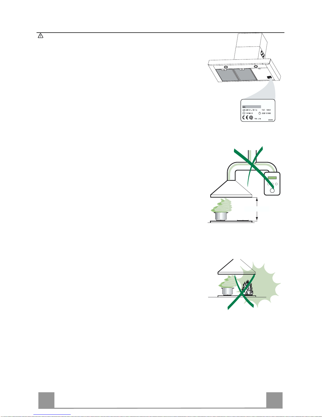
• The minimum safety distance between the cooker top and the extractor hood
is 650 mm.
• Check that the mains voltage corresponds to that indicated on the rating plate
fixed to the inside of the hood.
• For Class I appliances, check that the domestic power supply guarantees adequate earthi ng.
Connect the extractor to the exhaust flue through a pipe of minimum diameter
120 mm. The r oute of the f lue must be as short as possible.
• Do not connect the extractor hood to exhaust ducts carrying combustion fumes
(boilers, fireplac es, etc.).
• If the extractor is used in conjunction with non-electrical appliances (e.g. gas
burning appliances), a sufficient degree of aeration must be guaranteed in the
room in order to prevent the backflow of exhaust gas. The kitchen must have
an opening communicating directly with the open air in order to guarantee the
entry of clean air.
USE
• The extractor hood has been designed exclusively for domestic use to eliminate kitchen smells.
• Never use the hood for purposes other than for whi ch it has ben designed.
• Never leave high naked flames under the hood when it is in op eration.
• Adjust the flame intensity to direct it onto the bottom of the pan only, making
sure that it does not engulf the sides.
• Deep fat fryers must be continuously monitored during use: overheated oil can
burst into flames.
• Do not flambè under the range hood; r isk of fire
• This appliance is not intended for use by persons (including children) with reduced physical, sensory or mental capabilities, or lack of experience and
knowledge, unless they have been given supervision or instruction concerning
use of the a ppliance by a person r esponsible for their safety.
• Children should be supervised to ensure that they do not play with the appliance.
MAINTENANCE
• Switch off or unplug the appliance from the mains supply before carrying out
any maint enance work.
• Clean and/or re place the Fi lters after the speci fied time period.
• Clean the hood using a damp cloth and a neutral liquid detergent.
650 mm min.
Page 4
EN
116
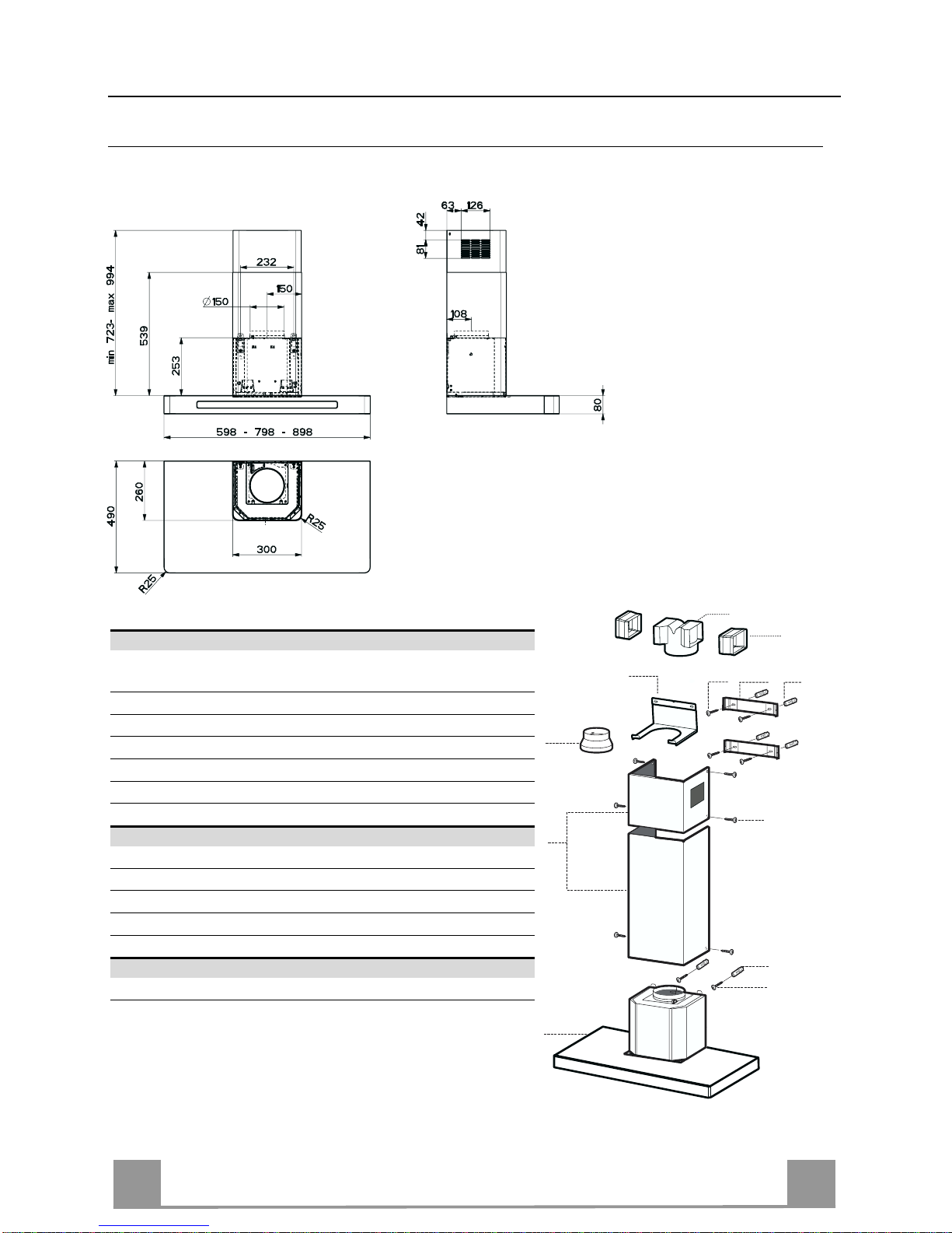
CHARACTERISTICS
Dimensions
Components
Ref. Q.ty Product Components
1 1 Hood Body, complete with: Controls, Light, Blower,
Filters
2 1 Telescopic Chimney comprising:
2.1 1 Upper Section
2.2 1 Lower Section
9 1 Reducer Flange ø 150-120 mm
14.1 2 Air Outlet C onnection Extensio n
15 1 Air Outlet C onnection
Ref. Q.ty Installation Components
7.2.1 2 Upper Chimney Section Fixing Brackets
7.3 1 Air Outlet C onnection Support
11 6 Wall Plugs
12a 6 Screws 4,2 x 44,4
12c 6 Screws 2,9 x 9,5
Q.ty Documentation
1 Instruction Manual
2.1
2.2
2
12c
12a
7.2.1 11
11
12a
1
9
7.3
14.1
15
Page 5

EN
117
INSTALLATION
Wall drilling and bracket fixing
Wall marking:
• Draw a vertical line on the supporting wall up to the ceiling, or as high as practical, at the
centre of the area in which the hood will be installed.
• Draw a horizontal line at 650 mm above the hob.
• Place bracket 7.2.1 on the wall as shown about 1-2 mm from the ceiling or upper limit aligning the centre (n otch) with the vertical reference line.
• Mark the wall at the centres of the ho les in the bracket.
• Place bracket 7.2.1 on the wall as shown at X mm below the first bracket (X = height of the
upper chimney section supplied), aligning the centre (notch) with the vertical line.
• Mark the wall at the centres of the ho les in the bracket.
• Mark a reference poi nt as indicated at 116 mm from the vertical referen ce line and 340 mm
above the horizontal reference line.
• Repeat this operation on the other side.
• Drill ø 8 mm holes at all the centre points marked.
• Insert the wall plugs 11 in the holes.
• Fix the lower bracket 7.2.1 using the 12a screws (4,2 x 44,4) supplied.
• Fix the upper bracket 7.2.1 and the air outlet connection support 7.3 together using the 2
screws 12a (4,2 x 44,4) supplied.
• Insert the two screws 12a (4,2 x 44,4) supplied in the hood body fixing holes, leaving a gap
of 5-6 mm between the wall and the head of the screw.
11
12a
340
X
116
1÷2
116
650 min.
7.2.1
Page 6

EN
118
Mounting the hood body
• Before attaching the hood body, tighten the two screws Vr located on the hood body mounting points.
• Hook the hood body onto the screws 12a.
• Fully tighten support screws 12a.
• Adjust screws Vr to level the hood body.
12a
Vr
Connections
DUCTED VERSION AIR EXHAUST SYSTEM
When installing the ducted version, connect the hood to the
chimney using either a flexible or rigid pipe ø 150 or 120 mm,
the choice of which is left to the installer.
• To install a ø 120 mm air exhaust connection, insert the reducer flange 9 on the hood body outlet.
• Fix the pipe in position using sufficient pipe clamps (not supplied).
• Remove any activated charcoal filters.
9
ø 120ø 150
RECIRCULATION VERSION AIR OUTLET
• Put connection 15 into the connection support 7.3.
• Insert the conn ection exten sion pieces lat erally 14.1 in co nnection 15.
• M ake sure that the outlet of the extensio n pieces 14.1 is horizontally and vertically aligned with the chimney outlets.
• Connect the air outlet connection 15 to the hood body outlet
using either a flexible or rigid pipe ø 150 mm, the choice of
which is left to the installer.
• Ensure that the activated charcoal filters have been inserted.
ø 150
14.1
15
Page 7

EN
119
ELECTRICAL CONNECTION
• Connect the hood to the mains through a two-pole switch having a contact gap of at least 3 mm.
• Remove the grease filters (see paragraph Maintenance) being
sure that the co nnector of the feeding cable is correctly inserted
in the socket placed on the side of the fan.
Flue assembly
Upper exhaust flue
• Slightly widen the two sides of the upper flue and hook them
behind the brackets 7.2.1, making sure that they are well
seated.
• Secure the sides to the brackets using the 4 screws 12c (2,9 x
9,5) supplied.
• Make sure that the outlet of the extensions pieces is aligned
with the chimney outlets.
Lower exhaust flue
• Slightly widen the two sides of the flue and hook them between the upper flue and the wall, making sure that they are
well seated.
• Fix the lower part laterally to the hood body using the 2 screws
12c (2,9 x 9,5) supplied.
12c
2.1
2.2
2
7.2.1
12c
Page 8

EN
220
USE
Control panel
Button Function Display
A Turns the suction motor on and off at the
last speed used.
Displays the speed set.
B Decreases the working speed. Decreases the lighted segment s.
C Increases the working speed. Increases the lighted segments.
D Activates intensive speed from any other
speed, including motor off. This speed is
timed to run for 10 minutes, after which
the system will return to the speed that
was previously set. Suitable for dealing
with severe cooking fumes.
I flashes and the segments on the Display are
all lit.
It is disabled by pressing the Button.
E Starts the motor at a speed that allows a
suction of 100 m
3
/h for 10 minut es every
hour, after which the motor stops.
Displays 24 and the segments on the Display,
initially all lit, turn off one at a time in cycle.
It is disabled by pressing the Button.
F Activates automatic switch-off with a 30’
delay. Suitable to complete elimination of
residual odours. Can be activated from any
position, it is deactivated by pressing the
button of turning the motor off.
Displays a flashing Clock symbol.
It is disabled by pressing the Button.
G Performs a Reset of the Filter saturation
alarm when the button is pressed for approximately 2 seconds.
After 100 hours operation the Drop symbol is
displayed to indicate saturation of the Metal
Grease Filter s.
After 200 hours operation the letter C is displayed to indicate saturation of the Activated
Charcoal Filters.
H Turns the Lightin g Syst em on and off.
Keyboard Lock Comman d: it is p ossible to l ock the keyboard , for example when cleanin g the
Glass, when the Hood Motor and Lights are turned off.
Press F (Delay) for approximately 5 seconds to enable or disable Keyboard Locking, which is
always confirmed by a Beep an d an animated signal o n the display motor bar.
B
A
D
C
E
H
G
F
Page 9

EN
221
MAINTENANCE
Cleaning the Comfort Panels
• Pull the Comfort Panel to open it.
• Disconnect the panel from the hood canopy by sliding the fixing pin lever.
• The comfort panel must never be washed in a dishwasher.
• Clean the outside using a damp cloth and neutral liquid detergent.
• Clean the inside as well using a damp cloth and neutral detergent; do not use wet cloths or sponges, or jets of water; do not
use abrasive substances.
• When the above operation has been completed, hook the panel
back to the hood canopy and close it by turning the knob in the
opposite direction .
Metal grease filters
Metal filters can be washed also in a dish machine. The y need to
be washed every time a drop-symbol appears in the display or at
least every two months. In case of very frequent use these have to
be washed even more often.
Alarm reset
• Press the G-key for at least 2 seconds.
Cleaning
• Open the comfort panel.
• Re move the filters one by one by pushing them backwards and
pulling them down contemporaneously.
• Wash the filters. Pay attention not to bend them. Make sure
that filters are completely dry before putting them into their
seat. (a possible modification of the filter surface doesn’t influence its efficiency).
• Place the filters again into their seats and make sure that the
handle of the filter remains outside.
• Close the comfort panel.
Page 10

EN
222
Charcoal filter (recycling version)
This filter cannot be washed or regenerated. It must be replaced when the C appears on the
display or at least once every 4 months. The filter saturation alarm has to be activated already
before.
Activation of the alar m signal
• In the recycling version hoods the filter saturation alarm must be activated during the installation or later.
• Switch off the hood and the lights.
• Press the E-key for about 5 seconds until the last two segments of the motor LEDS are lit on
the display.
• By releasing the E-key the clock icon starts to flash.
• Within 3 seconds press the D-key to activate/deactivate charco al filter saturation alarm.
• C-symbol lit - charcoal filter saturation alarm ACTIVATED.
• C-symbol unlit - ch arcoal filter saturation alarm DEACTIVATED.
SUBSTITUTION OF THE CHARCOAL FILTER
Alarm reset
• Switch off the motor and the lighting system.
• Press the G-key for at least 2 seconds.
Substitution of the filter
• Open the confort panel.
• Remove the metal grease filters.
• Remove the charcoal filter as indicated in th e picture.
• Place the filter again into its seat.
• Place again th e metal grease filters into their place.
Lighting
CHANGING LAMP
16 W Neon Lamp
• Open the comfort panel.
• Remove the neon lamp guard by unfastening the screws and
sliding it out of its housing.
• Change the Neo n l amp o r th e Start er, taking care to ensure th at
the new components have the same characteristics as the old
ones.
• Replace the neon lamp guard.
• Close the comfort panel.
Page 11

436003590_ver2
Il simbolo sul prodotto o sulla co nfezi on e indi ca che il prodo tto no n d eve ess ere c ons id era to co me un n ormal e r ifi uto dom es tic o,
ma deve ess ere port ato n el p unt o di rac c olta appr opri at o per i l r ic iclaggi o di appar ec chi atur e el ettri ch e ed el ettr oni ch e. Prov v ede ndo a
smaltire q ues to pro d otto i n m odo a ppro pri ato, s i contri bui sc e a evi t are p ote nzial i c onse gu enze nega tiv e per l’ ambi en te e p er la s alute,
che potrebbero deriv ar e da uno smaltimento inadeguato del prodotto. P er i nf or m az i o ni pi ù dettagliate sul rici c l aggi o di questo prodotto,
contattare l’uff icio comunale, il servizio locale di smaltimento rifiuti o il negozio in cui è stato acquistato il prodotto.
The symbol on the product or on its pac kaging indic a tes t hat this prod uct m ay not be treated as household waste. Inst ead it shall
be handed ov er to the applicable c ollectio n point for the recyc ling of elec trical and electroni c equipm ent. By ensur ing this product is
disposed of correctly, you will help prevent potential negative cons equences for the environment and human health, which could otherwise be caus ed by in appr opr iat e wast e han dli ng of this produc t. F or mor e detai led infor mati o n about recyc li ng of this produc t , ple ase
contact your local city office, your household waste disposal service or the shop where you purchased the product.
Le symbole sur le produit ou son em bal la ge in diqu e que c e pro d uit ne peut ê tre tr aité c omm e déc he t mén ager . Il d oit pl utôt être
remis au point de ramassage concerné, se chargeant du recyclage du matériel électrique et électronique. En vous assurant que ce
produit est él imi né correc temen t, vous favori sez l a préve ntion des conséq uenc es nég atives p our l’ envir onnem ent et la sa nté hum aine
qui, sinon, s er ai e nt l e r ésultat d’u n trai tement inap pr o pr i é d es d éc h ets d e c e produit. Pour o bt enir plus de détails sur l e rec yclage de ce
produit, veuillez prendre contact avec le bureau municipal de votre région, votre service d’élimination des déchets ménagers ou le
magasin où vo us av ez acheté le produi t.
Das Symbol auf dem Prod ukt oder seiner Verp acku ng weist d arauf hin, das s dies es Pro dukt n icht al s norm aler Haus halts abfal l
zu behand eln ist, s on der n an ein em S am mel pu nkt f ür das Recy cl ing v on elek tri sche n und elek troni sc he n Ger äte n ab geg ebe n w erde n
muss. Durc h Ihren Beitra g zum korr ekten Entsorgen dieses Produkts schützen Si e die Umwelt un d die Gesund h ei t I hr er M i tm e ns chen.
Umwelt und Gesundheit werden durch falsches Entsorgen gefährdet. Weitere Informationen über das Recycling dieses Produkts
erhalten Sie von Ihrem Rathaus, Ihrer Müllabfuhr oder dem Geschäft, in dem Sie das Produkt gekauft haben.
Ürün veya pak eti üzerindeki sembolü, bu ürünün normal bir evsel atık olarak gör ülmemesi ve bu tip elek trikli veya elektr onik
cihazları n atıldı ğı dönüşüm lü topl ama n oktal arına t erke dilm esi ger ektiğine işaret e der. B u ürünü g erekti ği gibi elim ine etm e kural ların a
uyarsanız çevre ve insan sağlığı üzerindeki olum suz etkilerini b ertaraf etmeye katk ı sağlamış olursunuz. B u ürünün geri d önüşüm
koşulları hakkında daha ayrıntılı bilgi için hudutları içinde bulunduğunuz belediyenin ilgili diaresine, atık yoketme servisine veya ürünün
satıcısına da nışınız.
Franke S.p.a.
Via Pignolini,2
37019 Peschiera del Garda (VR)
www.franke.it
73/23/CEE
Dir. 89/336/CEE
93/68/CEE
 Loading...