

Franke FIM/2 900 W XS, FIM/2 900 W XS WM, FIM/2 900 W XS WM WC, FIM 1100 W XS, FIM 1100 W XS WM Instructions For Use And Installation
...Page 1
Instructions for use and installation
Cooker Hood
Istruzioni per l’uso e l’installazione
Cappa
Mode d’emploi et installation
Hotte de Cuisine
Bedienungsanleitung und Einrichtung
Dunstabzugshaube
GB
IT
FR
DE
Instructies voor het gebruik en installeren
Dampkap
NL
110.0152.888 FIM/2 900 W XS
110.0154.426 FIM/2 900 W XS WM
110.0154.427 FIM/2 900 W XS WM WC
110.0082.408 FIM 1100 W XS
110.0082.410 FIM 1100 W XS WM
110.0082.411 FIM 1100 W XS WMC
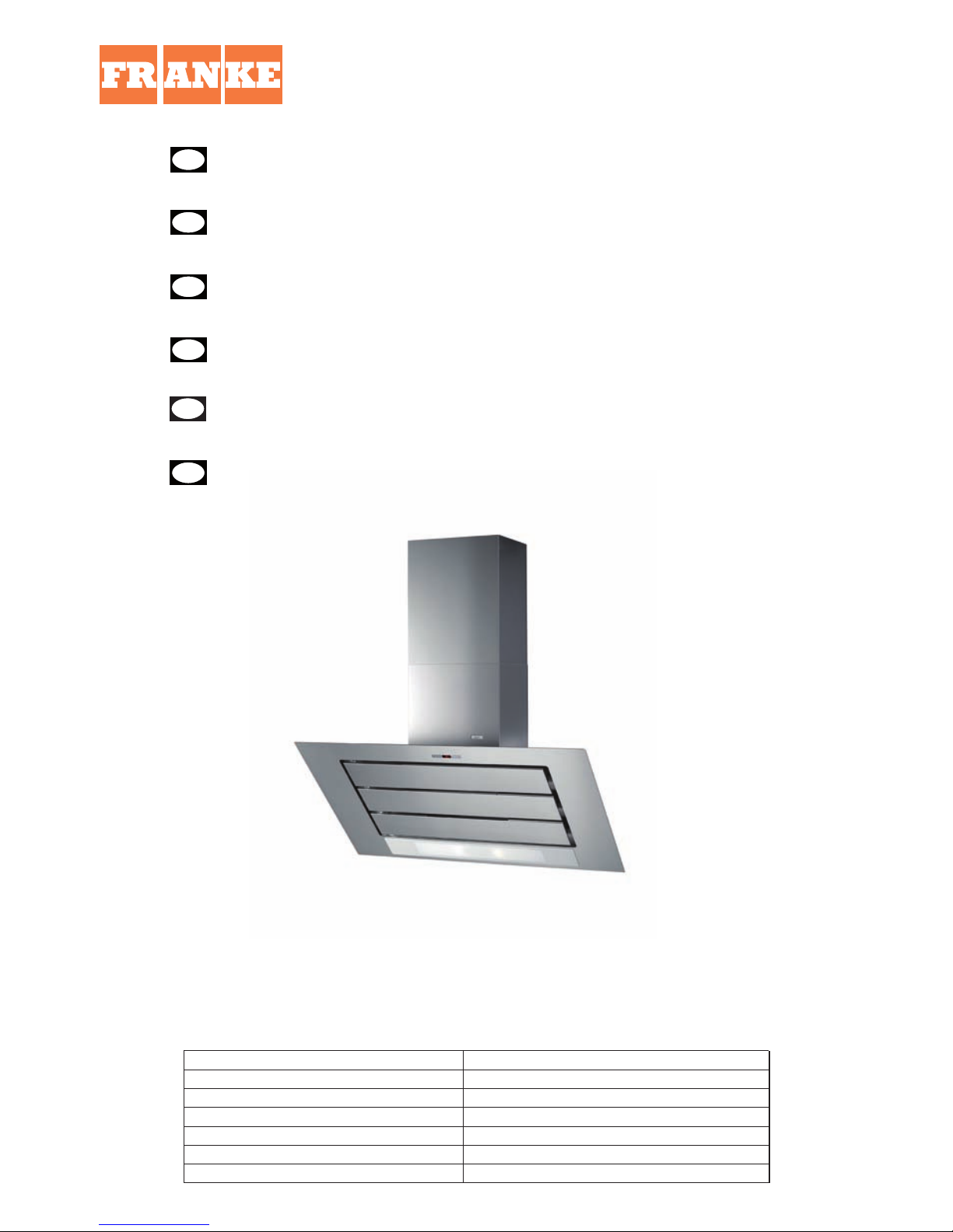
Imagine
Instrucciones de instalacion e utilizacion
Campana
E
Page 2
2
2
Instructions Manual
INDEX
RECOMMENDATIONS AND SUGGESTIONS .....................................................................................................................3
CHARACTERISTICS.............................................................................................................................................................4
INSTALLATION......................................................................................................................................................................5
USE........................................................................................................................................................................................8
MAINTENANCE.....................................................................................................................................................................9
GB
IT
FR
NL
CONSIGLI E SUGGERIMENTI............................................................................................................................................19
CARATTERISTICHE............................................................................................................................................................20
INSTALLAZIONE.................................................................................................................................................................21
USO......................................................................................................................................................................................24
MANUTENZIONE ................................................................................................................................................................25
Manuel d’Instructions
SOMMAIRE
CONSEILS ET SUGGESTIONS..........................................................................................................................................27
CARACTERISTIQUES.........................................................................................................................................................28
INSTALLATION....................................................................................................................................................................29
UTILISATION.......................................................................................................................................................................32
ENTRETIEN.........................................................................................................................................................................33
Gebruiksaanwijzing
INHOUDSOPGAVE
ADVIEZEN EN SUGGESTIES.............................................................................................................................................35
EIGENSCHAPPEN...............................................................................................................................................................36
INSTALLATIE.......................................................................................................................................................................37
GEBRUIK.............................................................................................................................................................................40
ONDERHOUD......................................................................................................................................................................41
E
Manual de instrucción
ÍNDICE
CONSEJOS Y SUGERENCIAS ..........................................................................................................................................43
CARACTERÍSTICAS .........................................................................................................................................................44
INSTALACIÓN ....................................................................................................................................................................45
UTILIZACIÓN.......................................................................................................................................................................48
94............................................ .....................................................................................................................OTNEIMINETNAM
DE
Bedienungsanleitung
INHALTSVERZEICHNIS
EMPFEHLUNGEN UND HINWEISE...................................................................................................................................11
CHARAKTERISTIKEN.........................................................................................................................................................12
MONTAGE...........................................................................................................................................................................13
BEDIENUNG........................................................................................................................................................................16
WARTUNG...........................................................................................................................................................................17
Libretto di Istruzioni
INDICE
Page 3
3
RECOMMENDATIONS AND SUGGESTIONS
The Instructions for Use apply to several versions of this appliance. Accordingly,
you may find descriptions of individual features that do not apply to your specific
appliance.
INSTALLATION
• The manufacturer will not be held liable for any damages resulting from incorrect or
improper installation.
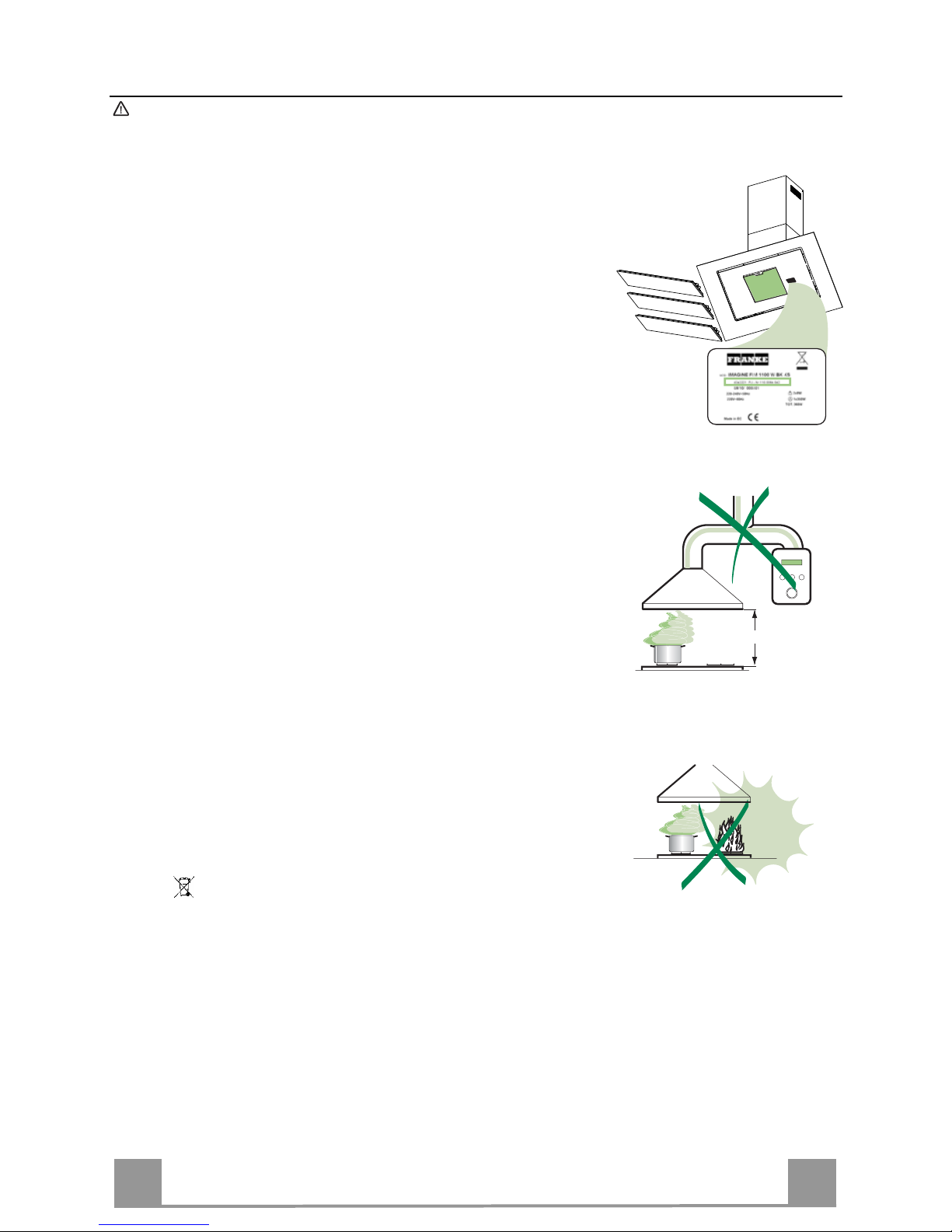
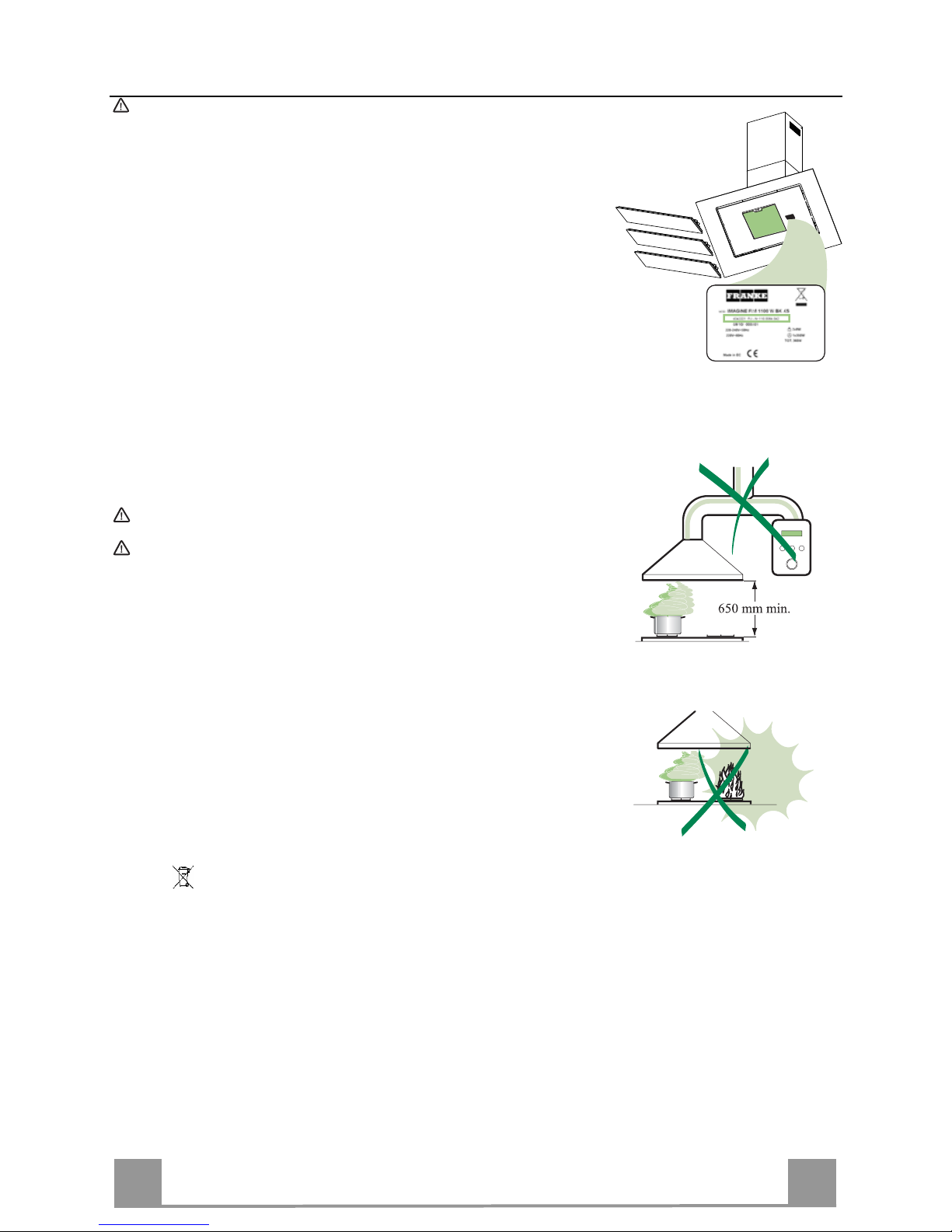
• The minimum safety distance between the cooker top and the extractor hood is 650
mm.
• Check that the mains voltage corresponds to that indicated on the rating plate fixed
to the inside of the hood.
• For Class I appliances, check that the domestic power supply guarantees adequate
earthing.
Connect the extractor to the exhaust flue through a pipe of minimum diameter 150
mm. The route of the flue must be as short as possible.
• Do not connect the extractor hood to exhaust ducts carrying combustion fumes
(boilers, fireplaces, etc.).
• If the extractor is used in conjunction with non-electrical appliances (e.g. gas burning appliances), a sufficient degree of aeration must be guaranteed in the room in
order to prevent the backflow of exhaust gas. The kitchen must have an opening
communicating directly with the open air in order to guarantee the entry of clean air.
USE
• The extractor hood has been designed exclusively for domestic use to eliminate
kitchen smells.
• Never use the hood for purposes other than for which it has been designed.
• Never leave high naked flames under the hood when it is in operation.
• Adjust the flame intensity to direct it onto the bottom of the pan only; making sure
that it does not engulf the sides.
• Deep fat fryers must be continuously monitored during use: overheated oil can burst
into flames.
• Do not flambé under the range hood; risk of fire
• This appliance is not intended for use by persons (including children) with reduced
physical, sensory or mental capabilities, or lack of experience and knowledge,
unless they have been given supervision or instruction concerning use of the appliance by a person responsible for their safety.
• Children should be supervised to ensure that they do not play with the appliance.
MAINTENANCE
• Switch off or unplug the appliance from the mains supply before carrying out any
maintenance work.
• Clean and/or replace the Filters after the specified time period.
• Clean the hood using a damp cloth and a neutral liquid detergent.
The symbol on the product or on its packaging indicates that this product may not be treated as
household waste. Instead it shall be handed over to the applicable collection point for the recycling
of electrical and electronic equipment. By ensuring this product is disposed of correctly, you will help
prevent potential negative consequences for the environment and human health, which could otherwise be caused by inappropriate waste handling of this product. For more detailed information about
recycling of this product, please contact your local city office, your household waste disposal service
or the shop where you purchased the product.
650 mm min.
GB
Page 4
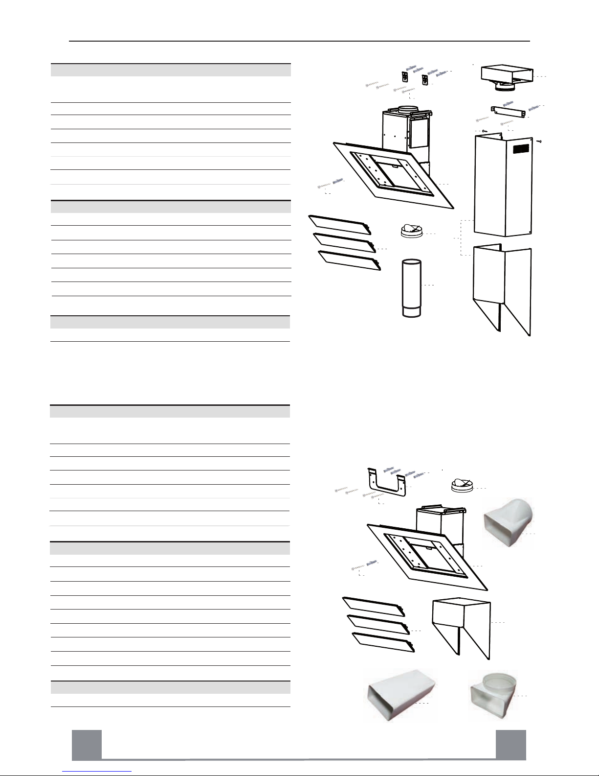
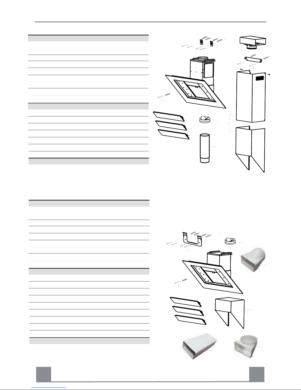
1 1 Cooker hood complete with control unit, lights,
blower unit, filters
2.1 1 Upper telescopic chimney
2.2 1 Lower telescopic chimney
3 3 Front cover
9 1 Valve ø 150 mm
m n s tenop oc no i t a l l a t sn I y t . Q . f eR
7.1 2 Hood fixing support piece
7.2 1 Upper chimney support piece
12c 2 Screws 4 x 10
1 Instruction booklet
14 1 Telescopic tube
15 1 Air outlet connection
11 7 Wall plugs ø 8
12a 3 Screws 4,5 x 50
12b 4 Screws 4,5 x 45
5
Components
Ref. Q.ty Product components
cumentation oD yt.Q
GB
11
7.1
12b
15
2.1
2.2
2
11
7.2
12a
12a
11
1
3
14
9
12c
CHARACTERISTICS
4
1 1 Cooker hood complete with control unit, lights,
blower unit, filters
2.3 Chimney cover 1
3 3 Front cover
9 1 Valve ø 150 mm
Ref. Q.ty Installation co pone ts nm
7.1 1 Hood fixing support piece
4 1 Transformation right rectangul ar/circular
5 1 Rectangular Tube
6 1 Transformation with 90° rectangular/circular
1 Instruction booklet
11 5 Wall plugs ø 8
12a 1 Screws 4,5 x 50
12b 4 Screws 4,5 x 45
cumentation oD yt.Q
Components (WMC Version)
Ref. Q.ty Product components
11
7.1
12b
2.3
12a
11
1
3
9
5
6
4
Page 5
GB
5
IN STALLATIO N
Any permanent electrical installation must comply with the latest regulations concerning this type of
installation and a qualified electrician must carry out the work. Non-compliance could cause serious
accidents or injury and would deem the manufacturers guarantee null and void.
IMPORTANT - The wires in this mains lead are coloured in accordance with the following code :
- green / yellow : earth - blue : neutral - brown : live
As the colours of the wires in the mains lead of this appliance may not correspond with the coloured
markings identifying the terminals in your plug, proceed as follows.
- The wire which is coloured green and yellow must be connected to the terminal in the plug which is
marked with the letter E or by the earth symbol or coloured green or green and yellow.
- The wire which is coloured blue must be connected to the terminal which is marked with the letter N
or coloured black.
- The wire which is coloured brown must be connected to the terminal which is marked with the letter L
or coloured red.
ATTENTION: Do not forget to use adequate plugs to the support brackets. Enquire after the
manufacturers. Do an embedding if necessary. The manufacturer accepts no responsibility in
case of a faulty hanging due to the drilling and the setting up of plugs.
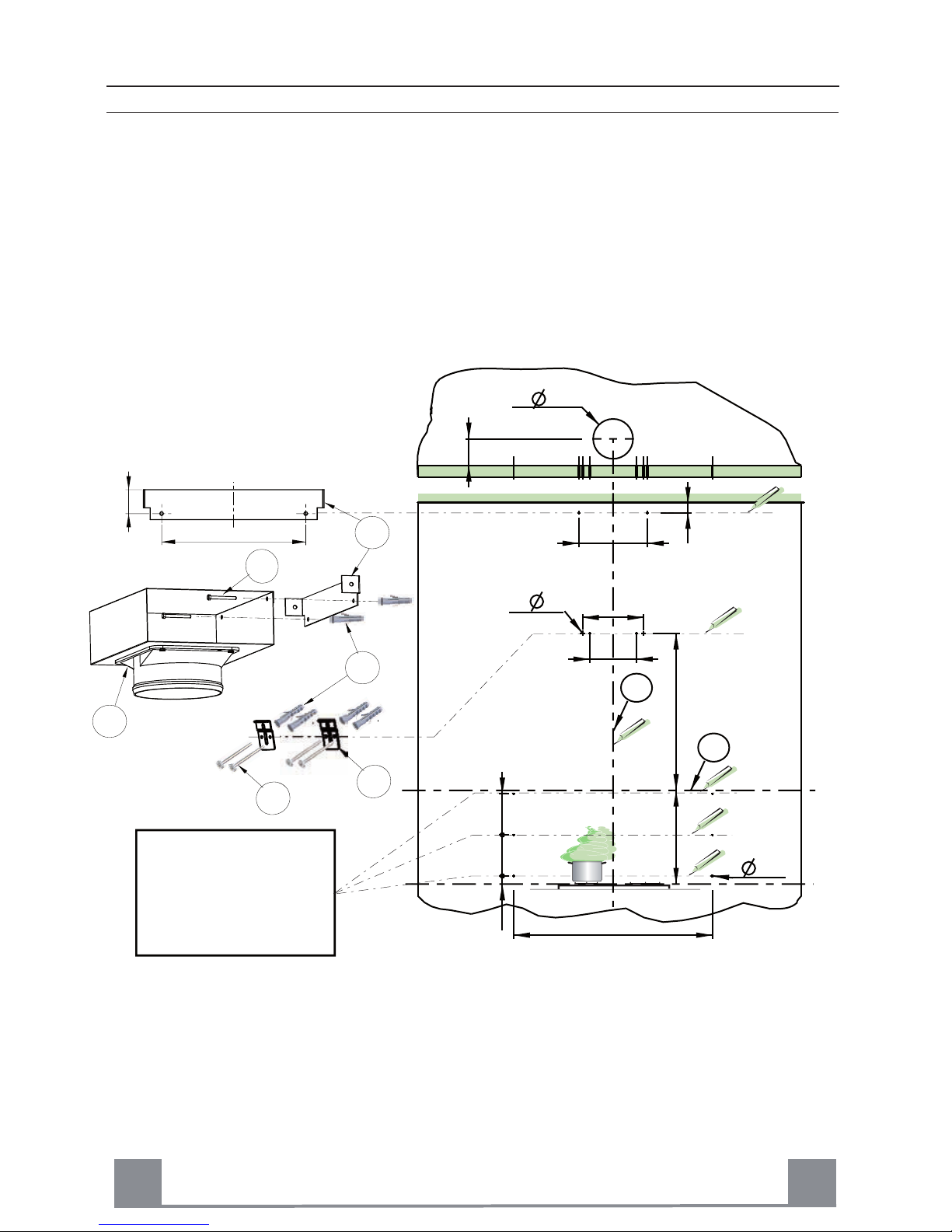
GB
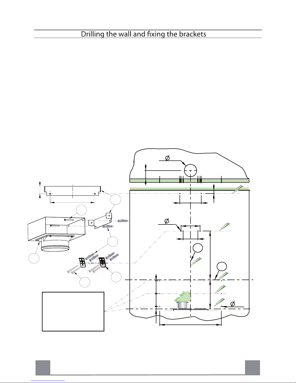
1) Draw a vertical line onto the wall from the centre of the cooking appliance up to the ceilling, using a
spirit level and a marker pen as illustrated ( item L1). This is to ensure the correct alignment of the
chimney hood.
170
113
6
260
40
293
35 175 175
3
848 - 1048
670
200
L2
H = 400
293
40
11
15
7.2
12a
7.1
12b
Crédence (Option)
Splachback (Optional)
Rückwand (Optional)
Fondale (Opzionale)
Panel (Opcional)
Spatscherm (Optie)
L1
Fig.1
Page 6
GB
2
2) Place the brackets item 7.2 on the wall about 1 or 2 mm from the ceiling or from the upper limit, aligning
its centre on the vertical line. Mark the two eyelet holes of the bracket onto the wall. Drill the holes
for the fixing bracket using an 8 mm masonry bit. Fix the chimney bracket item 7.2 using the screws
item 12a and rawl plugs item 11 supplied.
3) Mark a point on the vertical line at a distance from the cooking appliances of:
d = 1070 mm (Measurement without splashback).
d = height of the splashback (400 mm) + 670 mm (Measurement with splashback item B).
The distance H is the minimum height in mm from the cooking appliances to the bottom edge item L2 of
the front panel of the hood. Draw a horizontal line through the vertical as illustrated in Fig. 1.
Splashback (optional): When a splashback is to be fitted, the distance between the hood and the cook-
ing appliances will be determined by the height of the splashback item B and whether or not there
is a raised back on the worktop. The splashback is to be installed before installing the canopy. If
the splashback is to be fixed to the wall using both the top and bottom fixing holes, Care must be
taken to ensure that the splashback is fitted at the correct height before fixing the base units or at
least the worktop covering them. As this is a complex operation, it should only be undertaken by
the technician installing the kitchen units or by a competent person who knows the final dimensions
of the units.
Mark the hole centres for the canopy fixing brackets item 7.1 at item B mm as illustrated in Fig. 1.
Drill the 4 holes for the fixing brackets using an 8 mm masonry bit. Fix the wall brackets item 7.1 using
the screws item 12b and rawl plugs item 11 supplied.
10
10
30
1070
260
7.1
12a
11
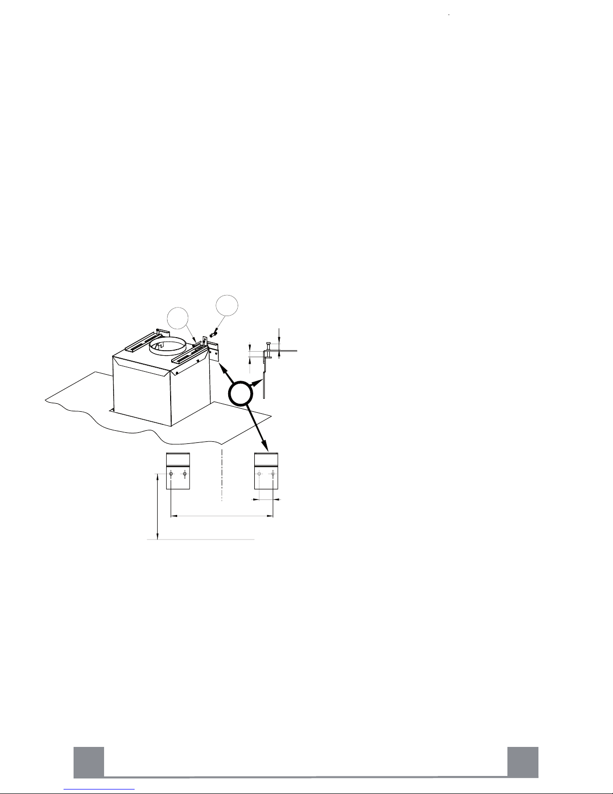
4) Hook the canopy item 1 onto the wall brackets
item 4 as illustrated in Fig. 2. To ensure the cooker
hood is aligned correctly adjust the screws on the top
of the canopy as illustrated
. When the hood is
aligned correctly mark the hole centre on the wall for
the security fixing screw
, which is located in the right
hand bracket on the top of the canopy. Unhook the
canopy from the wall and drill the hole for the security
fixing screw . Hook the canopy onto the wall and fix the
headed screw item 12.a and rawl plug item 11 to
secure the canopy to the wall.
5) Ducting:
The hood is more effective when used in the extraction mode (ducted to the outside). When the cooker
hood is ducted to the outside, charcoal filters are not required.The ducting used must be 150 mm (6
INS), rigid circular pipe and must be manufactured from fire retardant material, produced to BS.476
or DIN 4102-B1. Wherever possible use rigid circular pipe which has a smooth interior, rather than
the expanding concertina type ducting.
Maximum length of ducting run:
- 4 metres with 1 x 90° bend.
- 3 metres with 2 x 90° bends.
- 2 metres with 3 x 90° bends.
The above assumes our 150 mm (6 INS) ducting is being installed. Please note ducting components
and ducting kits are optional accessories and have to be ordered, they are not automatically sup-
Fig. 2
plied with the chimney hood.
6
Page 7
A
GB
2
7
a. IN THE EXTRACTION MODE:
Place the anti-backflow flats item 9 over the round outlet ,
the telescopic duct and connect the ducting 150mm (6 INS)
over the round outlet on top of the canopy and secure the
connections withappropriate clamping rings or adhesive
tape (
Fig. 3).
b. Remove the grease filters (see paragraph Maintenance)
Fig. 4 being sure that the connector of the
mains cable is
correctly inserted in the socket placed on the sides of the fan.
Before fitting the chimney to the canopy make the electrical
connection as described in the section titled ELECTRICAL.
When the electrical connection has been made, test the
lights and the fan motor.
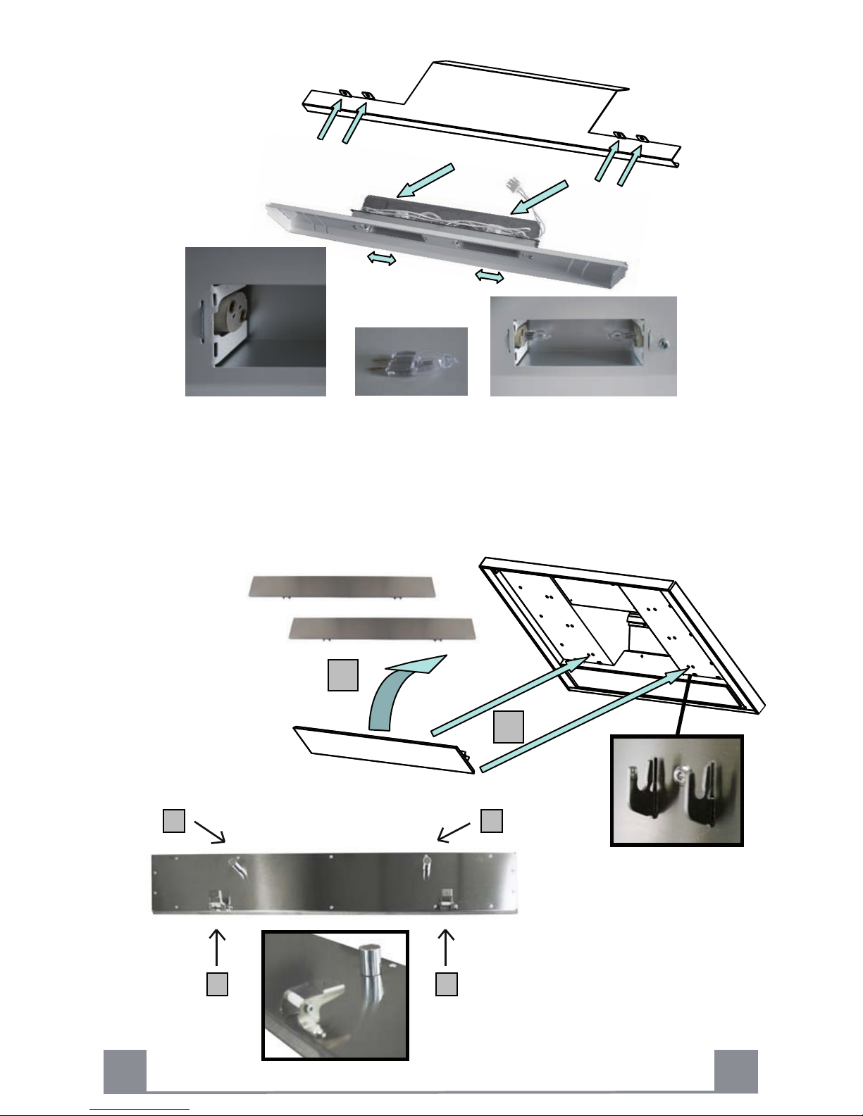
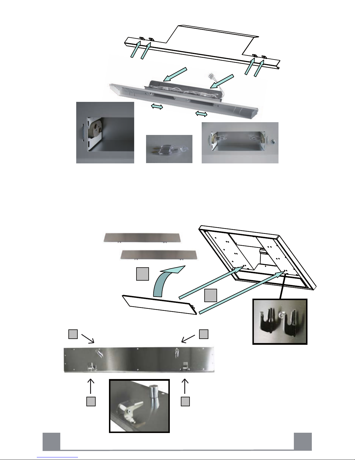
d. Each chimney stack consists of two sections. Fit the upper sections
(Fig. 6 - item 2.1 & 2.2) first by expanding the chimneys slightly to
allow them to clamp around the bracket item 7.1 and secure the
chimney stacks to the brackets using the two M4 screws item 12c
provided. Fit the lower chimney
sections by expanding the chimneys
e. Fit the 3 front cover Item 3 - Fig 10.
IN THE RECIRCULATION MODE:
Fit the recirculation spigot 15 onto the upper chimney wall
bracket using the same fixing screws (Fig. 1 item 7.1).
Connect the ducting 150mm (6 INS) not provided between
motor and the recirculation spigot item 15 and secure the
connections with appropriate clamping rings or adhesive
tape (Fig. 3)..
c. IN THE RECIRCULATION MODE: Insert the charcoal
filter
into the base of the motor housing and secure the filter with
two metal securing straps item A as illustrated in Fig. 5.
f. IN THE REMOTE MOTOR MODE AND WITHOUT CHIMNEY:
Note: The Fig. 7 & 8 correspond to the versions without Motor and without chimney (SMC or WMC).
15
9
Fig. 3
Fig. 4
slightly to allow them from the top of the canopy to clamp around the
upper chimney sections.
12c
2.2
2.1
Fig. 5
Fig. 6
Page 8
1
2
8
USE
GB
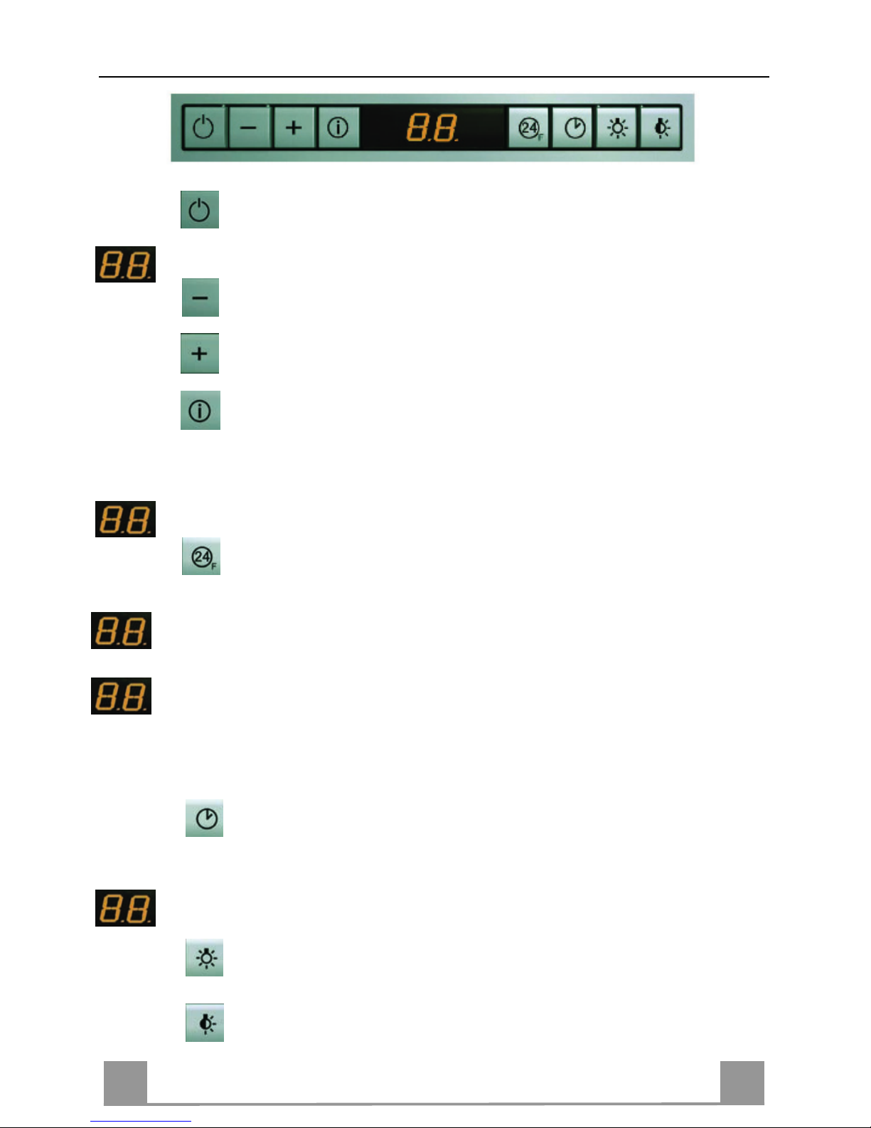
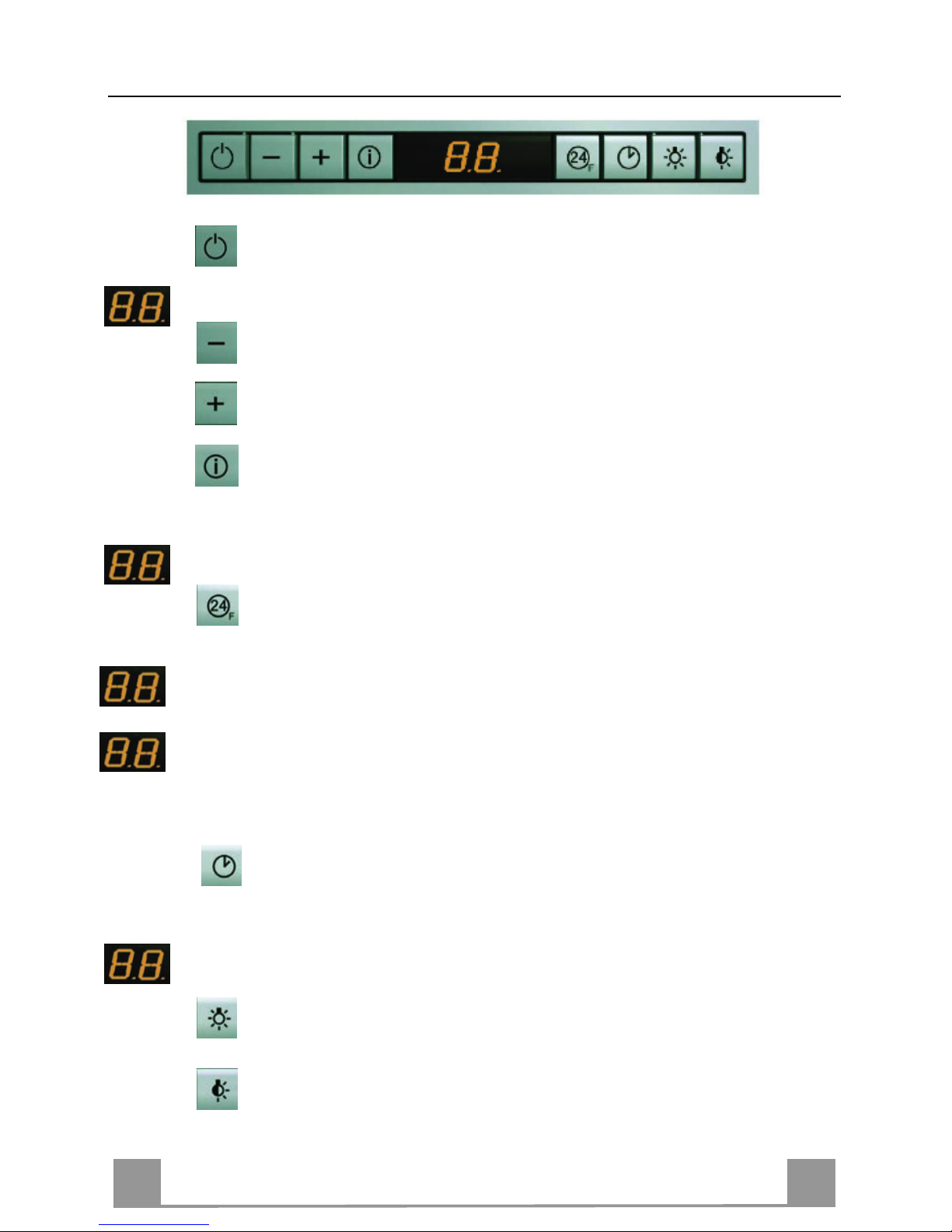
Control board
Key : On / Off
Switches the extractor motor on and off at the latest selected speed.
Indicates the selected speed.
Key
: Speed control
Decreases the suction speed.
Key
: Speed control
Increases the suction speed.
Key : Intensive speed
By pressing this key it is possible to activate the intensive speed from any previously se-lected speed.
The intensive speed can be acti-vated even when the motor is OFF. This speed has been timed at 10
minutes. After that time the system activates automatically the latest selected speed. This function is
suitable for cooking conditions when vapours and smells are of the utmost emission.
HI appears. The spot down on the right side ashes once a second.
Key
: Air Renewing
By pressing this key it is possible to set up the motor to a suction speed at 100 m3/h lasting 10 minutes every hour. After this the motor switches off automatically.
Indicates the 24-function. The spot down on the right side ashes and the motor is on.
When the lter saturation is going on it is pos-sible to reset the alarm by pressing this key
for about 3 seconds. The indication is visible only when the motor is off.
Once the process is nished the previous indi-cation disappears:
FF Indicates that the metal grease lters saturation alarm has been triggered, and the lters
need to be washed. The alarm is triggered after 100 working hours.
EF Indicates that the charcoal lter satura-tion alarm has been triggered, and the l-ter has
to be replaced; the metal grease lters must also be washed. The charcoal lter is triggered after 200
working hours.
Key : Stop delay 30 minutes
By pressing this key it is possible to set the delayed shutdown of the appliance to 30 min-utes. This
function is suitable for a complete elimination of the residual smells. It can be activated at any position,
and it is deactivated by pressing the key again or by switching off the motor.
Indicates alternately the selected speed of the hood and the time left before the hood shut-
down. The spot down on the right side ashes.
Key
: Lighting
Turns light on and off .
Key
: Lighting
Turns the second light unit on and off (ambient lighting).
Page 9
GB
9
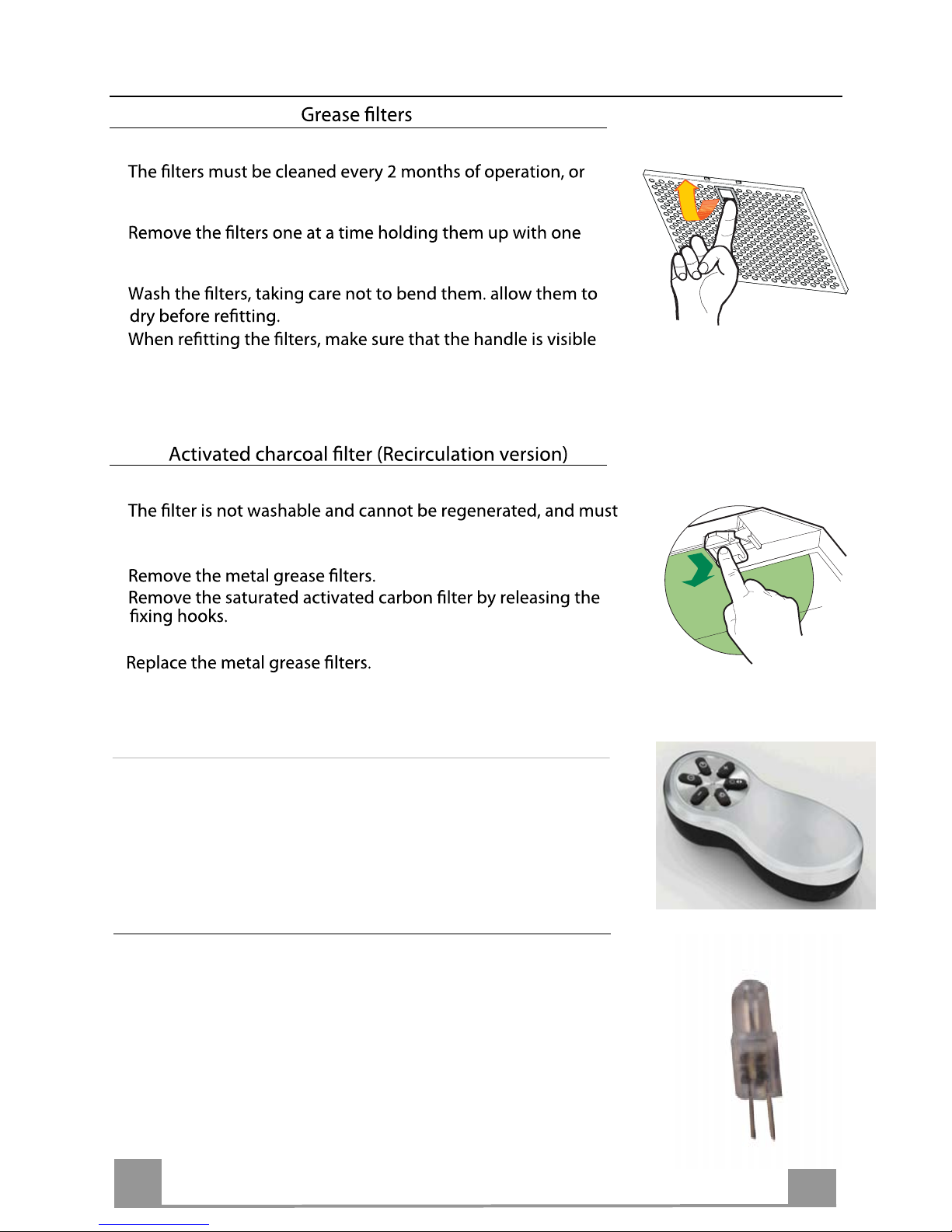
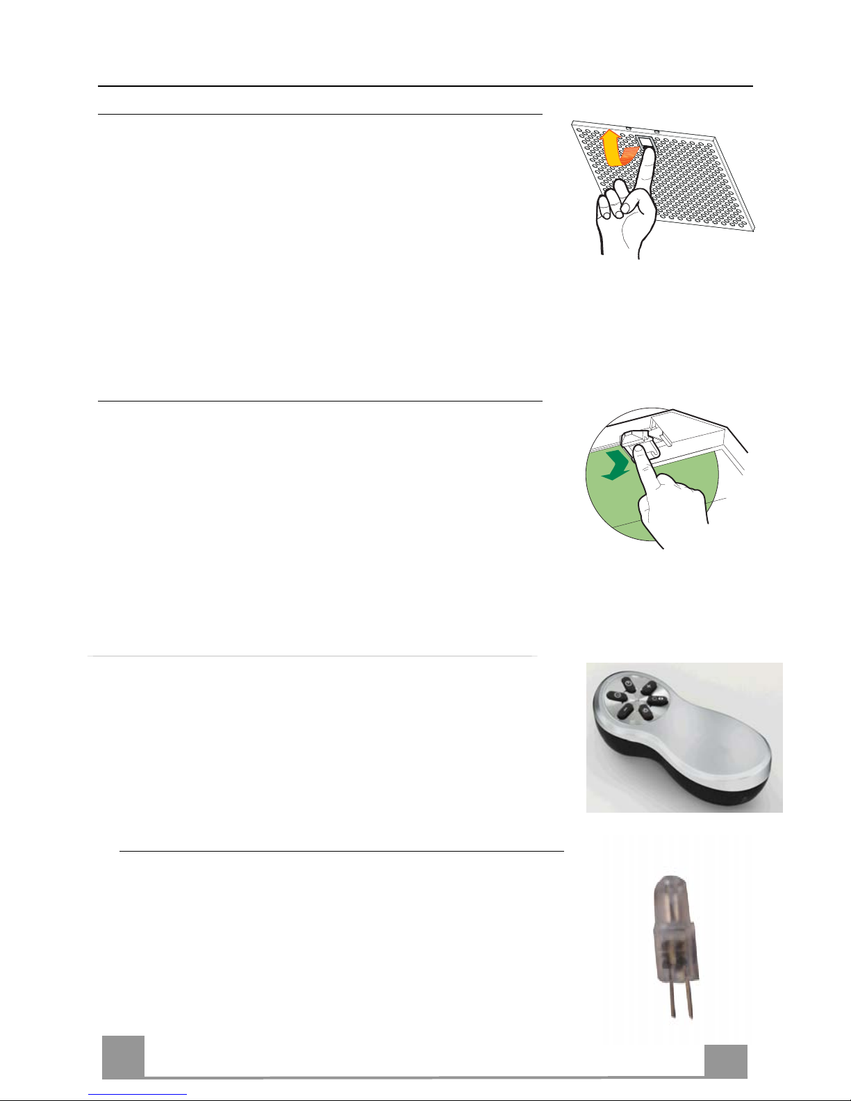
•
more frequently for particularly heavy usage, and can be
washed in a dishwasher.
•
hand and pulling the handle downwards with the other hand
at the same time.
•
•
on the outside.
•
be replaced approximately every 4 months of operation, or
more frequently for particularly heavy usage.
•
•
•
•
• Indication of saturation of the metal grease filters and reset of
the 200 hours timer (See chapter USE control G)
• Indication of saturation of the charcoal filters and reset of
the 400 hours timer (See chapter USE control G)
Remote control (Otional )
MAINTENANCE
CLEANING METAL SELF- SUPPORTING GREASE FILTERS
REPLACING THE ACTIVATED CHARCOAL FILTER
Fit the new by hooking it into its seating.
The appliance can be controlled using a remote control powered
by a 1.5 V carbon-zinc alkaline batteries of the standard LR03AAA type.
• Do not place the remote control near to heat sources.
• Used batteries must be disposed of in the proper manner.
• Remove the metal cover (2 or 4 screws).
• Remove the lamp housing gently (2 screws).
• Replace the lamp with a new one of the same type, making
sure that you insert the two pins properly into the housings
on the lamp holder.
• Replace the lamp housing and then the metal cover.
Lighting
LIGHT REPLACEMENT
G4 20 W 12 V
Page 10
10
GB
1
2
11
2 2
Fig. 9
Fig. 10
Page 11
DE
11
EMPFEHLUNGEN UND HINWEISE
Diese Gebrauchsanleitung gilt für mehrere Geräte-Ausführungen. Es ist möglich, dass
einzelne Ausstattung
en beschrieben sind, die nicht auf Ihr Gerät zutreffen.
MONTAGE
• Das Gerät darf nur vom Fachpersonal angeschlossen werden.
• Der Hersteller haftet nicht für Schäden, die auf eine fehlerhafte und unsachgemäße Mon-
tage zurückzuführen sind.
• Der minimale Sicherheitsabstand zwischen Kochmulde und Haube muss 650 mm betra-
gen.
• Prüfen, ob die Netzspannung mit dem Wert auf dem im Haubeninneren angebrach-
ten Schild übereinstimmt.
• Bei Geräten der Klasse I ist sicherzustellen, dass die elektrische Anlage des Wohnhauses
über eine vorschriftsmäßige Erdung verfügt.
• Das Anschlussrohr der Haube zur Luftaustrittsöffnung sollte möglicherweise einen
Durchmesser von 150 mm aufweisen. Der Rohrverlauf muss so kurz wie möglich sein.
• Die Haube darf an keine Entlüftungsschächte angeschlossen werden, in die Verbren-
nungsgase (Heizkessel, Kamine usw.) geleitet werden.
• Werden im Raum außer der Dunstabzugshaube andere, nicht elektrisch betriebene (z.B.
gasbetriebene) Geräte verwendet, muss für eine ausreichende Belüftung gesorgt werden.
Sollte die Küche diesbezüglich nicht entsprechen, ist an einer Aussenwand eine Öffnung
anzubringen, die Frischluft gewährleistet.
BEDIENUNG
• Die Dunstabzugshaube ist ausschließlich zum Einsatz im privaten Haushalt und zur Be-
seitigung von Küchengerüchen vorgesehen.
• Bei unsachgemäßer Benutzung wird keine Haftung übernommen.
Achtung! Große Flammen bei eingeschalteter Haube niemals unbedeckt lassen.
• Die Intensivität der Flamme ist so zu regulieren, dass sie den Topfboden nicht überragt.
Achtung! Frittiergeräte müssen während des Gebrauchs stets beaufsichtigt werden: Überhitztes Öl kann sich entzünden.
• Keine flambierten Speisen unter der Abzugshaube zubereiten: Brandgefahr.
• Dieses Gerät darf nicht von Personen, auch Kindern, mit verminderten psychischen,
sensorischen und geistigern Fähigkeiten, oder von Personen ohne Erfahrung und Kenntnisse benutzt werden, sofern sie nicht von für ihre Sicherheit verantwortlichen Personen
beaufsichtigt und beim Gebrauch des Geräts angeleitet werden.
• Kinder dürfen sich nicht unbeaufsichtigt in der Nähe des Geräts aufhalten und auf keinen
Fall mit dem Gerät spielen.
WARTUNG
• Bevor Wartungsarbeiten durchgeführt werden, muss die Stromzufuhr zur Haube unter-
brochen werden, indem der Stecker gezogen oder der Hauptschalter abgeschaltet wird.
• Bei der Filterwartung müssen die vom Hersteller empfohlenen Zeiträume zum Austau-
schen der Filter genauestens eingehalten werden.
• Zur Reinigung der Haubenflächen empfehlen wir ein feuchtes Tuch und ein mildes Flüs-
sigreinigungsmittel.
• Bitte keine Reinigungsmittel mit Scheuermittel verwenden. Die Oberfläche wird damit
verkratzt.
Das Symbol auf dem Produkt oder seiner Verpackung weist darauf hin, dass dieses Produkt nicht als
normaler Haushaltsabfall zu behandeln ist, sondern an einem Sammelpunkt für das Recycling von elektrischen und elektronischen Geräten abgegeben werden muss. Durch Ihren Beitrag zum korrekten Entsorgen
dieses Produkts schützen Sie die Umwelt und die Gesundheit Ihrer Mitmenschen. Umwelt und Gesundheit
werden durch falsches Entsorgen gefährdet. Weitere Informationen über das Recycling dieses Produkts
erhalten Sie von Ihrem Rathaus, Ihrer Müllabfuhr oder dem Geschäft, in dem Sie das Produkt gekauft haben.
Page 12
DE
2
12
1 1 Haubenkörper komplett mit : Steuerungen,
Beleuchtung, Gebläsegruppe, Filtern
2.1 1 Oberer Kaminteil
2.2 1 Unterer Kaminteil
3 3 Verkleidung
9 1 Ventilklappe ø 150 mm
1 Gebrauchsanweisung
14 1 Teleskopische Röhre
15 1 Anschlussstück Luftaustritt
Bez. St. Installations ko pone te nm
7.1 2 Haubenhalterungen
7.2 t i negnur e t l ah len imaK erebO 1
11 7 Dübel ø 8
12c 2 Schrauben 4 x 10
12a 3 Schrauben 4,5 x 50
12b 4 Schrauben 4,5 x 45
Bez. St. Produktkomponente
S t D o noi tatnemuk.
Komponenten
CHARAKTERISTIKEN
1 1 Haubenkörper komplett mit : Steuerungen,
Beleuchtung, Gebläsegruppe, Filtern
2.3 1 Schutzhülle Kaminteil
3 3 Verkleidung
9 1 Ventilklappe ø 150 mm
1 Gebrauchsanweisung
Bez. St. Installations ko pone te nm
7.1 1 Haubenhalterungen
11 7 Dübel ø 8
12a 3 Schrauben 4,5 x 50
12b 4 Schrauben 4,5 x 45
Bez. St. Produktkomponente
S t D o noi tatnemuk.
Komponenten (WMC Version)
4 1 Umwandlung rechteckiges/kreisförmiges 90°
5 1 Rechteckige Röhre
6 1 Rechteckige/kreisförmige gerade Umwandlung
11
7.1
12b
15
2.1
2.2
2
11
7.2
12a
12a
11
1
3
14
9
12c
11
7.1
12b
2.3
12a
11
1
3
9
5
6
4
Page 13
13
170
113
6
260
40
293
35 175 175
3
848 - 1048
670
200
L2
H = 400
293
40
11
15
7.2
12a
7.1
12b
Crédence (Option)
Splachback (Optional)
Rückwand (Optional)
Fondale (Opzionale)
Panel (Opcional)
Spatscherm (Optie)
L1
Fig.1
DE
MONTAGE
Bohren der Befestigungslöcher und Fixieren der Befestigungsbügel
Montage und Anschluß müssen von einem qualifizierten Installateur* durchgeführt werden.
(*) Wenn diese Bedingung nicht eingehalten wird, wird die Garantie des Herstellers, sowie jeder
Anspruch im Falle eines Unfalles aufgehoben.
Achtung ! Bitte beachten Sie bei der Montage das Gewicht der kompletten Dunstesse.
Die Tragfähigkeit der Decke oder alternativ der Trägerplatte für diese Zugbelastung muss
vor der Montage geprüft und gegebenenfalls durch die Anbringung von geeigneten
Befestigungs-oder Stabilisierungselementen hergestellt werden. Kann eine hinreichende
Tragfähigkeit nicht sichergestellt werden, ist von einer Montage abzusehen.
1) An der Wand eine vertikale Linie L1 (Abb. 1) bis zur Decke zeichnen (Mittellinie des
Bereiches, indem die Haube montiert werden soll), um die zu montierenden Einzelteile
vertikal ausrichten zu können.
2) Einen der Bügel 7.2 (Abb. 1) ca. 1-2 mm von der Decke oder der oberen
Begrenzung an die Wand legen und den Mittelpunkt auf der vertikalen Linie ausrichten.
Die beiden ösenförmigen Bohrlöcher des Bügels an der Wand markieren.
Page 14

2
10
10
30
1070
260
7.1
12a
11
Fig. 2
14
DE
3) Einen Punkt auf der vertikalen Linie L2 kennzeichnen,
der folgenden Abstand zur Kochmulde aufweist: d = min. 1070 (Maß ohne Rückwand).
d =Rückwandhöhe (400 mm) + 670 mm (Maß mit Rückwand B).
Das Maß H ist die Mindesthöhe in mm von der Kochmulde zur unteren Frontkante L2.
Rückwand (Optional): Der Abstand der Haube von der Kochmulde wird in diesem Fall
von der Höhe der Rückwand B und des eventuell anzubringenden Aufsatzes an der
Arbeitsplatte bestimmt. Die Rückwand wird vor Montage des Haubenkörpers angebracht;
will man die Rückwandoben und unten mit der Wand verschrauben, muss sie auf die
gewünschte Höhe ausgerichtet werden, bevor der Unterschrank oder die Arbeitsplatte
montiert wird. Da es sich hierbei um einen relativ komplizierten Vorgang handelt, sollte
er nur vom Küchenmontagepersonal oder von fachlich geschulten Personen, die die
Endmasse der Möbel genau kennen, durchgeführt werden.
Für die Unterkante des Gerätes eine Einbauhöhe (L2) bestimmen,um die Stützen zu
positionieren. ( Pos. 7.1) (Abb. 1 & 2).
4) Montage des Haubenkörpers:
Der Haubenkörper (1) wird an den
Wandstützen befestigt. Die Regelung
und das Ausrichten der Dunstesse
von außen mit den Schrauben 5 x 10
der Stützenund mit den zwei Schrauben
5 x 25 mm kontrollieren. Nachdem Sie
alle Einstellungen durchgeführt haben,
verriegeln Sie die Dunstesse durch die
Befestigungsschraube , um das
unbeabsichtigte Aushängen zu vermeiden.
Diese positiveBefestigungsschraube ist
durch eine farbige Aufschrift gekennzeichnet,
die sich im Oberteil des Geräte-Gehäuses
befindet.
Befestigungsschraube
5) Anschluss für Abluft- oder Umluftbetrieb:
a- • Abluftbetrieb : Die Rückstauklappe (Pos .9) am Gerätsausgang anbringen, der
Teleskopscheide auf den Flansch des Gerätes einfügen. Schlauch am Gerätsausgang
anbringen (Abb. 3) und anschliessen. Beim Anschluss passende Schlauchschellen oder
Klebeband benutzen.
Page 15

A
2
15
15
9
Fig. 3
Fig. 4
12c
2.2
2.1
Fig. 5
Fig. 6
DE
• Umluftbetrieb : Den Umluftadapter 15 an den Oberkamin
hängen. Der Umluftadapter wird mit denselben Schrauben
wie für die Oberkaminstütze befestigt (Abb. 2 – Pos. 7.2).
Ein Verbindungsrohr/Schlauch mit passendem
Durchmesser (nicht im Lieferumfang) am Lufteintritt
des Umluftadapters und am Gebläseausgang
anschliessen. Beim Anschluss passende Schlauchschellen
oder Klebeband benutzen.
b- Entfernen Sie die Fettfilter (s. Abschnitt "Wartung“)
und versichern Sie sich, dass die Kabelverbindung in
die Steckdose des Gebläses einwandfrei montiert wird (Abb. 4).
Das Gerät ans Wechselstromnetz anschliessen (siehe
Abschnitt Netzanschluss) und Funktion von Beleuchtung,
Motor und der elektronischen Steuerung (Gebläseleistung)
prüfen.
c- Die Stütze der Aktivkohle-Filters befestigen und mittels
Druck auf die Elemente A (Abb. 5) Aktivkohle-Filterkassette
einrasten.
d- Den Oberkamin in den Teleskop-Unterkamin (Abb.6 Pos. 2.1 & 2.2)
einfügen und mit den beigelegten Schrauben (Pos. 12 c)
an die Stütze (Pos. 7.2) hängen. Danach den Oberkamin um
den Haubenkörper falzen.
e- Die 3 Verkleidung (Abb.10 Pos. 3) festzulegen.
f- Ohnemotorbetrieb und ohne Kamin
Bemerkung : Die Abb. 7 & 8 sind für Versionen ohne Motor und
ohne Kamin ( SMC oder WMC).
Page 16
DE
3
6
16
BEDIENUNG
Bedienung
Taste : Ein / Aus
Schaltet den Motor der Absauganlage bei der zuletzt verwendeten Geschwindigkeit ein und aus.
Zeigt die eingestellte Leistungsstufe an.
Taste
: Minimale Stufe
Vermindert die Betriebsgeschwindigkeit.
Taste
: Maximal Stufe
Erhöht die Betriebsgeschwindigkeit.
Taste : Intensive Stufe
Aktiviert von jeder Geschwindigkeit aus, auch bei abgestelltem Motor, die Intensivgeschwindigkeit, die
auf 10 Minuten zeitgeregelt ist. Nach Ablauf dieser Zeit kehrt das System zu der zuvor eingestellten
Geschwindigkeit zurück. Für die Beseitigung von sehr intensiven Kochdünsten geeignet.
Zeigt HI an und der Punkt unten rechts blinkt einmal pro Sekunde.
Taste
: Durchlüftung
Aktiviert den Motor bei einer Geschwindigkeit, die eine Absaugleistung von 100 m3/h für die Dauer
von 10 Minuten jede Stunde ermöglicht, nach dessen Ablauf hält der Motor an.
Zeigt 24 an und der Punkt unten rechts blinkt, während der Motor in Betrieb ist.
Bei laufendem Filteralarm wird durch 3 Sekunden anhaltendes Drücken der Taste ein
Reset des Alarms ausgelöst. Dererlei Anzeigen sind nur bei abgestelltem Motor sichtbar.
Nach abgeschlossener Prozedur verlöscht die bisherige Anzeige:
FF zeigt an, dass der Metallfettlter gewaschen werden muss. Dieser Alarm wird nach 100
effektiven Betriebsstunden der Abzugshaube ausgelöst.
EF zeigt an, dass die Aktivkohlelter ausgewechselt und die Metallfettlter gewaschen werden müssen. Dieser Alarm wird nach 200 effektiven Betriebsstunden der Abzugshaube ausgelöst.
Taste : Abschaltautomatik (30 Minuten Nachlauf)
Aktiviert das automatische Ausschalten mit einer Verzögerung von 30 Min. Ermöglicht die Beseitigung
von Restgerüchen und kann von jeder Position aus aktiviert werden. Zum Deaktivieren die Taste
drücken oder den Motor abstellen.
Zeigt abwechselnd die Betriebsgeschwindigkeit und die bis zum Abschalten der Abzugs-
haube verbleibende Zeit an. Der Punkt unten rechts blinkt.
Taste
: Beleuchtung
Schaltet die Beleuchtung ein oder aus.
Taste
: Beleuchtung
Macht die zweiten lichtergrup an und aus (Atmosphäre Lichter).
Page 17
2
17
WARTUNG
AUSTAUSCHEN DER AKTIVKOHLE FILTER
Fettlter
REINIGUNG der SELBSTTRAGENDEN METALLFETTFILTER
• Sie müssen nach 2-monatigem Betrieb bzw. bei starkem
Einsatz auch häufiger gereinigt werden, was im Geschirrspüler
möglich ist.
• Einen Filter nach dem anderen entfernen. Halten Sie den Filter
mit einer Hand fest und ziehen Sie den Griff mit der anderen
Hand gleichzeitig nach unten.
• Die Filter reinigen und vor dem Wiedereinbau trocknen
lassen.
• Beim Wiedereinbau ist darauf zu achten, dass sich der Griff auf
der sichtbaren Außenseite befindet.
• Sättigungsanweisung der Metallfettlter und Alarm Steuerung
(Siehe Absatz "Bedienung" taste G).
Aktivkohlefilter (Umluftversion)
• Dieser Filter kann weder gewaschen noch wiederverwendet
werden und ist alle 4 Betriebsmonate bzw. bei starkem Einsatz
auch häufiger auszutauschen.
• Die Metallfettfilter entfernen.
• Den gesättigten Aktivkohlefilter aushaken.
• Den neuen Filter in seinem Sitz einhaken.
• Die Metallfettfilter wieder montieren.
• Sättigungsanweisung der Aktivkohlelter und Alarm Steuerung
(Siehe Absatz "Bedienung" taste G).
• Die Kohlefilter konnen mit dem Hausmüll entsorgt werden.
Fernbedienung (OPTION)
Dieses Gerät kann mit einer Fernbedienung gesteuert werden,
welche mit alkalischen Zink-Kohle-Batterien 1,5V des Standardtyps LR03-AAA versogt wird.
• Die Fernbedienung nicht in die Nähe von Hitzequellen legen.
• Batterien müssen vorschriftsmässig entsorgt werden.
Beleuchtung
AUSWECHSELN DER LAMPEN
• Die metallische Deckel entfernen (4 oder 2 Schrauben).
• Die Lampe aus der Halterung nehmen.
• Die Lampe durch eine gleichwertige ersetzen und beim Wie-
dereinsetzen darauf achten, daß die beiden Steckerstifte vor-
schriftsmäßig in die Lampenfassung eingeführt werden.
• Die metallische Beleuchtung-Gehäuse entfernen (2 Schrauben).
• Die metallische Deckel und die Beleuchtung-gehause wieder einzusetzen .
DE
G4 20 W 12 V
Page 18
8
18
DE
1
2
11
2 2
Fig. 9
Fig. 10
Page 19

IT
1
19
CONSIGLI E SUGGERIMENTI
Questo libretto di istruzioni per l'uso è previsto per più versioni dell'apparecchio.
È possibile che siano descritti singoli particolari della dotazione, che non riguardano
il Vostro apparecchio.
INSTALLAZIONE
• Il produttore declina qualsiasi responsabilità per danni dovuti ad installazione non
corretta o non conforme alle regole dell’arte.
• La distanza minima di sicurezza tra il Piano di cottura e la Cappa deve essere di
650 mm.
• Verificare che la tensione di rete corrisponda a quella riportata nella targhetta posta
all’interno della Cappa.
• Per Apparecchi in Classe Ia accertarsi che l’impianto elettrico domestico garantisca
un corretto scarico a terra.
• Collegare la Cappa all’uscita dell’aria aspirata con tubazione di diametro pari o
superiore a 150 mm. Il percorso della tubazione deve essere il più breve possibile.
• Non collegare la Cappa a condotti di scarico dei fumi prodotti da combustione
(caldaie, caminetti, ecc.).
• Nel caso in cui nella stanza vengano utilizzati sia la Cappa che apparecchi non
azionati da energia elettrica (ad esempio apparecchi utilizzatori di gas), si deve
provvedere ad una aerazione sufficiente dell’ambiente. Se la cucina ne fosse
sprovvista, praticare un’apertura che comunichi con l’esterno, per garantire il
richiamo d’aria pulita.
USO
• La Cappa è stata progettata esclusivamente per uso domestico, per eliminare gli
odori della cucina.
• Non fare mai uso improprio della Cappa.
• Non lasciare fiamme libere a forte intensità sotto la Cappa in funzione.
• Regolare sempre le fiamme in modo da evitare una evidente fuoriuscita laterale
delle stesse rispetto al fondo delle pentole.
• Controllare le friggitrici durante l’uso: l’olio surriscaldato potrebbe infiammarsi.
• Non preparare alimenti flambè sotto la cappa da cucina: pericolo d'incendio.
• Questo apparecchio non deve essere utilizzato da persone (bambini inclusi) con
ridotte capacità psichiche, sensoriali o mentali, oppure da persone senza
esperienza e conoscenza, a meno che non siano controllati o istruiti all’uso
dell’apparecchio da persone responsabili della loro sicurezza.
• I bambini devono essere sorvegliati per assicurarsi che non giochino con
l’apparecchio.
MANUTENZIONE
• Prima di procedere a qualsiasi operazione di manutenzione, disinserire la Cappa
togliendo la spina elettrica o spegnendo l’interruttore generale.
• Effettuare una scrupolosa e tempestiva manutenzione dei Filtri secondo gli intervalli
consigliati.
• Per la pulizia delle superfici della Cappa è sufficiente utilizzare un panno umido e
detersivo liquido neutro.
Il simbolo sul prodotto o sulla co nfezione indica che il pr odotto non deve essere c onsiderato
come un normale rifiuto dome stico, ma deve essere portat o nel punto di raccolt a appropriato per il
riciclaggio di apparecchiature elettriche ed elettroniche. Provvedendo a smaltire questo prodotto in
modo appropriato, si contribuisce a evitare potenziali conseguenze negative per l’ambiente e per la
salute, che potrebbero derivare da uno smaltimento inadeguato del prodotto. Per informazioni più
dettagliate sul riciclaggio di questo prodotto, contattare l’ufficio comunale, il servizio locale di
smaltimento rifiuti o il negozio in cui è stato acquistato il prodotto.
Page 20

IT
1
20
1 1 Corpo Cappa completo di : Comandi, Luce,
Gruppo Ventilatore, Filtri
2.1 1 Camino Telescopico Superiore
2.2 1 Camino Telescopico Inferiore
3 3 Pannello Finitura
9 1 V ø 150 mm
Rif. Q.tà Componenti di Installazione
7.1 2 Supporto Attacco Cappa
7.2 1 Supporto Camino Superiore
12c 2 Viti 4 x 10
1 Libretto Istruzioni
14 1 Tubo telescopico
15 1 Raccordo Uscita Aria
11 7 Tasselli ø 8
12a 3 Viti 4,5 x 50
12b 4 Viti 4,5 x 45
Q.tà Do azionetnemuc
Componenti
Rif. Q.tà Componenti di Prodotto
CARATTERISTICHE
1 1 Corpo Cappa completo di : Comandi, Luce,
Gruppo Ventilatore, Filtri
2.3 1 Mascera del Camino
3 3 Pannello Finitura
9 1 V ø 150 mm
Rif. Q.tà Componenti di Installazione
7.1 1 Supporto Attacco Cappa
1 Libretto Istruzioni
11 7 Tasselli ø 8
12a 3 Viti 4,5 x 50
12b 4 Viti 4,5 x 45
Q.tà Do azionetnemuc
Componenti (WMC Versione)
Rif. Q.tà Componenti di Prodotto
4 1 Trasformazione 90° rettangolare/circolare
5 1 Tubo rettangolare
6 1 Trasformazione diritta rettangolare/circolare
11
7.1
12b
15
2.1
2.2
2
11
7.2
12a
12a
11
1
3
14
9
12c
11
7.1
12b
2.3
12a
11
1
3
9
5
6
4
Page 21

21
170
113
6
260
40
293
35 175 175
3
848 - 1048
670
200
L2
H = 400
293
40
11
15
7.2
12a
7.1
12b
Crédence (Option)
Splachback (Optional)
Rückwand (Optional)
Fondale (Opzionale)
Panel (Opcional)
Spatscherm (Optie)
L1
Fig.1
IT
INSTALLAZIONE
Il montaggio ed il collegamento devono esere realizzati da un istallatore qualificato *.
(*) Il non rispetto di questa condizione provocherà l’annullamento della garanzia del
costruttore e tutti i ricorsi in caso di incidente.
Attenzione: usare dei tasselli adatti al supporto, informarsi presso i fabbricanti, effettuare
una sigillatura se necessario. La società declina ogni responsabilità in caso di agganciatura
difettosa dovuta alla perforazione ed al fissaggio.
1) Tracciare sulla parete una linea verticale fino al soffitto, al centro della zona prevista per il
montaggio della cappa (Fig. 1, rif. L1); questa operazione serve ad effettuare l’allineamento
verticale delle diverse parti della cappa.
2) Posizionare il supporto del camino sulla parete (Fig. 1 , rif. 7.2), allineando il suo centro sulla linea
verticale, ad 1-2 mm.dal soffitto o dal limite superiore. Segnare sulla parete i due fori asolati del
supporto. Forare la parete con una punta Ø 8 mm e fissare il supporto (Rif. 7.2) usando le viti (12a)
ed i tasselli in dotazione.
Page 22

2
10
10
30
1070
260
7.1
12a
11
Fig. 2
22
IT
3) Segnare un punto sulla linea verticale ad una distanza dal piano di cottura di:
d = 1070 min (misura senza fondale).
d = altezza fondale (400 mm) + 670 mm (misura con fondale rif.B).
La misura H é l’altezza minima in mm dal piano di cottura al bordo inferiore della cappa (rif. L2).
Definire la posizione della parte bassa della cappa (rif L2) per fissare i supporti (Fig2, rif 7.1).
• Fondale (opzionale): L’altezza della cappa dal piano di cottura è determinata, in questo caso,
dall’altezza del fondale B e dalla eventuale alzatina del piano di lavoro. Il fondale va montato
prima di montare il corpo cappa, e, se si desidera fissarlo contro la parete sia nella parte superiore
che nella parte inferiore, è necessario montarlo alla giusta altezza, prima del montaggio delle
basi o almeno del relativo piano superiore. Essendo questa operazione complessa, va effettuata
esclusivamente dall’installatore della cucina o da personale competente che conosca tutte le
dimensioni finali dei mobili.
4) Montaggio del corpo cappa :
Appendere la cappa (rif 1) sui supporti murali.
Perfezionare l’allineamento dell’insieme
dall’esterno con l’aiuto delle viti dei supporti
TH 5 x 25 el’inclinazione con l’aiuto delle 2
viti 5 x 25 mm TC. Dopo aver effettuato tutti
gli allineamenti dell’insieme della cappa,
bloccarla con una vite di fissagio positivo (rif 8)
per garantirne la sicurezza. Questa vite é
reperibile grazie ad un’etichetta colorata esi
trova nella parte alta della struttura della cappa.
fissagio positivo
5) Connessione
a-
• Per la versione evacuazione esterna : Mettere la valvola di non ritorno (Rif. 9) sull’uscita
dell’apparecchio , Incastrare l’elemento del tubo telescopico e raccordare il tubo
flessibile (Fig. 3) all’evacuazione esterna ed all’uscita dell’apparecchio. Fissare l’assieme tramite
collari o nastro adesivo appropriati.
Page 23

A
2
23
15
9
Fig. 3
Fig. 4
12c
2.2
2.1
Fig. 5
Fig. 6
IT
• Per installazione in versione filtrante:
Fissare il deflettore (Rif. 15) al supporto del camino superiore.
Il deflettore è fissato con le stesse viti del supporto del camino
superiore (Fig. 1, Rif. 7.2)
Istallare un tubo di diametro appropriato (non fornito) e
raccordarlo all’uscita dell’apparecchio ed all’entrata del
deflettore. Fissare l’assieme tramite collari o nastro
adesivo appropriati.
b- Togliere i filtri metallici, poi verificare che il connettore del cavo
di alimentazione sia ben inserito nella presa del motore (Fig. 4).
Raccordare elettricamente la cappa (vedi paragrafo Collegamento Elettrico)
e verificare il buon funzionamento delle luci, del motore e del
cambiamento delle velocità di aspirazione.
c- Per installazione in versione filtrante: Posizionare le cartucce
a carbone attivo negli appositi alloggiamenti, esercitando una
pressione sulle linguette A (Fig. 5).
d- Camino superiore: Allargare leggermente i due bordi laterali
(Fig. 6, Rif. 2.1) ed agganciarli dietro. Infilare la parte alta del camino
nella parte bassa del camino telescopico (Fig. 6, Rif. 2.1 & 2.2) Fissare
il camino superiore al supporto (Rif. 7.2) con 2 viti M4 fornite (Rif.12c)
poi far scivolare il camino inferiore fino al blocco motore.
e- Fissare i 3 deflettori (Fig. 10, Rif.3).
f- Per la versione senza motore e senza camino :
Nota: Le figure 7 e 8 corrispondono alle versioni senza motore
e senza camino (SMC o WMC).
Page 24

IT
2
0
24
USO
Quadro comandi
Tasto : Acceso / Spento
Accende e spegne il motore di aspirazione all’ultima velocità utilizzata.
Visualizza la velocità impostata.
Tasto
: Regolazione Velocità
Decrementa la velocità di esercizio.
Tasto
: Regolazione Velocità
Incrementa la velocità di esercizio.
Tasto : Velocità intensiva
Attiva la velocità intensiva da qualsiasi velocità anche da motore spento, tale velocità è temporizzata
a 10 minuti, al termine del tempo il sistema ritorna alla velocità precedentemente impostata. Adatta a
fronteggiare le massime emissioni di fumi di cottura.
Visualizza HI e il punto in basso a destra lampeggia una volta al secondo.
Tasto
: Renovacion del aire
Attiva il motore ad una velocità che consente un’aspirazione di 100 m3/h per 10 minuti ogni ora, terminati il motore si ferma.
Visualizza 24 e il punto in basso a destra lampeggia, mentre il motore è in funzione.
Con l’allarme ltri in corso premendo il tasto per circa 3 secondi si effettua il reset dell’allarme. Tali segnalazioni sono visibili solo a motore spento.
Terminata la procedura si spegne la segnalazione precedentemente visualizzata:
FF segnala la necessità di lavare i ltri antigrasso metallici. L’allarme entra in funzione dopo
100 ore di lavoro effettivo della Cappa.
EF segnala la necessità di sostituire i ltri al carbone attivo e devono anche essere lavati i
ltri antigrasso metallici. L’allarme entra in funzione dopo 200 ore di lavoro effettivo della Cappa.
Tasto : Arresto differito 30 minuti
Attiva lo spegnimento automatico ritardato di 30’. Adatto per completare l’eliminazione di odori residui.
Attivabile da qualsiasi posizione, si disattiva premendo il tasto o spegnendo il motore.
Visualizza alternativamente la velocità di esercizio e il tempo rimanente allo spegnimento
della cappa. Il punto in basso a destra lampeggia.
Tasto
: Luci
Accende e spegne l’impianto di illuminazione .
Tasto
: Riduzione intensità luci
Accende e spegne l’impianto di illuminazione ad intensità ridotta.
Page 25

IT
2
25
SOSTITUZIONE FILTRO ANTIODORE AL CARBONE ATTIVO
Illuminazione
SOSTITUZIONE LAMPADE
PULIZIA FILTRI ANTIGRASSO METALLICI AUTOPORTANTI
•
(vedi paragrafo "USO", tasto G ).
Filtro antiodore (Versione Filtrante)
Filtri antigrasso
• Sono lavabili anche in lavastoviglie, e necessitano di essere
lavati ogni 2 mesi circa di utilizzo o più frequentemente, per un
uso particolarmente intenso.
• Togliere i Filtri uno alla volta,sostenendoli con una mano
mentre con l’altra si tira la leva verso il basso.
• Lavare i Filtri evitando di piegarli, e lasciarli asciugare prima
di rimontarli.
• Rimontarli facendo attenzione a mantenere la maniglia verso la
parte visibile esterna
• Non è lavabile e non è rigenerabile, va sostituito almeno ogni 4
mesi o più frequentemente, per un uso particolarmente intenso.
• Togliere i Filtri antigrasso metallici.
• Rimuovere il Filtro antiodore al Carbone attivo saturo, agendo
sugli appositi agganci.
• Montare il nuovo Filtro agganciandolo nella sua sede.
• Rimontare i Filtri antigrasso metallici.
•
(vedi paragrafo "USO", tasto G ).
• Togliere la maschera metallica (4 o 2 viti).
• Estrarre la lampadina alogena dal portalampada.
• Sostituirla con una nuova lampadina di uguali caratteristiche,
facendo attenzione ad inserire correttamente i due spinotti nella
sede del portalampade.
• Rimontare la cassa e la maschera metallica .
• Togliere la cassa luce (2 viti).
MANUTENZIONE
Telecomando (OPZIONALE)
Questo apparecchio può essere comandato per mezzo di un telecomando, alimentato con pile alcaline zinco-carbone da 1,5 V del
tipo standard LR03-AAA.
• Non riporre il telecomando in prossimità di fonti di calore.
• Non disperdere le pile nell'ambiente, depositarle negli appositi
contenitori.
G4 20 W 12 V
Page 26

8
26
IT
1
2
11
2 2
Fig. 9
Fig. 10
Page 27

FR
2
27
CONSEILS ET SUGGESTIONS
La présente notice d'emploi vaut pour plusieurs versions de l'appareil. Elle peut contenir des
descriptions d'accessoires ne figurant pas dans votre appareil.
INSTALLATION
• Le fabricant décline toute responsabilité en cas de dommage dû à une installation non cor-
recte ou non conforme aux règles de l’art.
• La distance minimale de sécurité entre le plan de cuisson et la hotte doit être de 650 mm au
moins.
• Vérifier que la tension du secteur correspond à la valeur qui figure sur la plaquette apposée à
l’intérieur de la hotte.
• Pour les Appareils appartenant à la Ière Classe, veiller à ce que la mise à la terre de
l’installation électrique domestique ait été effectuée conformément aux normes en vigueur.
• Connecter la hotte à la sortie d’air aspiré à l’aide d’une tuyauterie d’un diamètre égal ou supé-
rieur à 150 mm. Le parcours de la tuyauterie doit être le plus court possible.
• Eviter de connecter la hotte à des conduites d’évacuation de fumées issues d’une combus-
tion tel que (Chaudière, cheminée, etc…).
• Si vous utilisez des appareils qui ne fonctionnent pas à l’électricité dans la pièce ou est instal-
lée la hotte (par exemple: des appareils fonctionnant au gaz), vous devez prévoir une aération suffisante du milieu. Si la cuisine en est dépourvue, pratiquez une ouverture qui communique avec l’extérieur pour garantir l’infiltration de l’air pur.
UTILISATION
• La hotte a été conçue exclusivement pour l’usage domestique, dans le but d’éliminer les
odeurs de la cuisine.
• Ne jamais utiliser abusivement la hotte.
• Ne pas laisser les flammes libres à forte intensité quand la hotte est en service.
• Toujours régler les flammes de manière à éviter toute sortie latérale de ces dernières par
rapport au fond des marmites.
• Contrôler les friteuses lors de l’utilisation car l’huile surchauffée pourrait s’enflammer.
• Ne pas préparer d’aliments flambés sous la hotte de cuisine : risque d’incendie
• Cet appareil ne doit pas être utilisé par des personnes (y compris les enfants) ayant des
capacités psychiques, sensorielles ou mentales réduites, ni par des personnes n’ayant pas
l’expérience et la connaissance de ce type d’appareils, à moins d'être sous le contrôle et la
formation de personnes responsables de leur sécurité.
• Les enfants doivent être surveillés pour s'assurer qu'ils ne jouent pas avec l'appareil.
ENTRETIEN
• Avant de procéder à toute opération d’entretien, retirer la hotte en retirant la fiche ou en ac-
tionnant l’interrupteur général.
• Effectuer un entretien scrupuleux et en temps dû des Filtres, à la cadence conseillée.
• Pour le nettoyage des surfaces de la hotte, il suffit d’utiliser un chiffon humide et détersif
liquide neutre.
Le symbole sur le produit ou son emballage indique que ce produit ne peut être traité comme déchet
ménager. Il doit plutôt être remis au point de ramassage concerné, se chargeant du recyclage du matériel
électrique et électronique. En vous assurant que ce produit est éliminé correctement, vous favorisez la
prévention des conséquences négatives pour l’environnement et la santé humaine qui, sinon, seraient le
résultat d’un traitement inapproprié des déchets de ce produit. Pour obtenir plus de détails sur le recyclage
de ce produit, veuillez prendre contact avec le bureau municipal de votre région, votre service d’élimination
des déchets ménagers ou le magasin où vous avez acheté le produit.
Page 28

FR
28
1 1 Corps de Hotte comprenant : Commandes ,
Eclairage, Groupe Ventilation, Filtres
2.1 1 Conduit télescopique Supérieur
2.2 1 Conduit télescopique Inférieur
3
9 1 Clapet ø 150 mm
1 Notice
14 1 Tuyau télescopique
15 1 Raccord Sortie d'air
3 Lamelle
Ref. Q.té Composants d'installation
7.1 1 Support Hotte
7.2 1 Support Conduit Supérieur
12c 2 Vis 4 x 10
11 7 Chevilles ø 8
12a 3 Vis 4,5 x 50
12b 4 Vis 4,5 x 45
cumentation oD ét.Q
Composants
Ref. Q.té Composants du produit
CARACTERISTIQUES
11
7.1
12b
15
2.1
2.2
2
11
7.2
12a
12a
11
1
3
14
9
12c
11
7.1
12b
2.3
12a
11
1
3
9
5
6
4
1 1 Corps de Hotte comprenant : Commandes ,
Eclairage, Groupe Ventilation, Filtres
2.3 1 Habillage Conduit
3
9 1 Clapet ø 150 mm
Ref. Q.té Composants d'installation
7.1 1 Support Hotte
1 Notice
11 7 Chevilles ø 8
12a 3 Vis 4,5 x 50
12b 4 Vis 4,5 x 45
Q . t é D o noi tatnemuc
Composants (Version WMC)
Ref. Q.té Composants du produit
3 Lamelle
4 1 Transformation 90° rectangulaire / circulaire
5 1 Tube rectangulaire
6 1 Transformation droite rectangulaire / circulaire
Page 29

29
170
113
6
260
40
293
35 175 175
3
848 - 1048
670
200
L2
H = 400
293
40
11
15
7.2
12a
7.1
12b
Crédence (Option)
Splachback (Optional)
Rückwand (Optional)
Fondale (Opzionale)
Panel (Opcional)
Spatscherm (Optie)
L1
Fig.1
FR
INSTALLATION
Montage et raccordement doivent être réalisés par un installateur* qualifié.
(*) Le non-respect de cette condition entraîne la suppression de la garantie du constructeur et
tout recours en cas d’accident.
Attention: prendre bien soin d’employer les chevilles adaptées au support, se renseigner au près
des fabricants, effectuer un scellement si nécessaire. La société décline toute responsabilité en
cas d’accrochage défectueux dû au perçage et chevillage.
1) Tracer sur la paroi une verticale jusqu’au plafond à l’emplacement de la hotte au centre de la zone
prévue pour le montage de la hotte (Fig.1, rep. L1). Cette ligne sert pour aligner verticalement les
différentes parties.
2) Positionner le support de conduit ( Rep. 7.2), centré sur la verticale à 1 à 2 mm du plafond ou de la
limite supérieure et marquer sur la paroi les deux alésages du support. Effectuer sur la paroi deux trous
avec un foret Ø 8 mm. Fixer le support de
conduit (Rep. 7.2) à l’aide des
vis 12a et des chevilles 11 fournies.
Page 30

10
10
30
1070
260
7.1
12a
11
Fig. 2
FR 30
3) Définir le bas de la hotte (Rep L2) afin de fixer les supports au mur (Fig 1, Rep 7.2).
Marquer un point sur la ligne verticale à une distance du plan de cuisson de :
d = 1070 min (mesure sans crédence).
d = hauteur crédence (400 mm) + 670 mm (mesure avec crédence B).
La hauteur H est la hauteur minimum en mm du plan de cuisson au bas de la hotte (Rep. L2).
Crédence (Option) : La hauteur de la hotte par rapport au plan de cuisson est déterminée,
dans ce cas par la hauteur de la crédence Rep B et par l’éventuel dosseret du plan de travail.
La crédence doit être montée avant le corps de la hotte et si l’on désire la fixer contre le mur
tant en haut qu’en bas, il est nécessaire de la positionner à la juste hauteur. Etant donné qu’il
s’agit d’une opération compliquée, elle doit être effectuée exclusivement par l’installateur de la
cuisine ou par du personnel compétent connaissant toutes les dimensions finales des meubles.
Effectuer sur la paroi 4 trous avec un foret Ø 8 mm. Fixer les support (Rep. 7.2) à l’aide des vis
12b et des chevilles fournies.
4) Montage du corps de la hotte :
Accrocher le corps (Rep 1) sur les supports
muraux. Parfaire le réglage d’alignement de
l’ensemble, à l’aide des vis TH 5 x 25 des
supports, ainsi que l’inclinaison à l’aide des
2 vis 5 x 25 mm TC.
Après avoir effectué tous les réglages
d’alignement de l’ensemble de la hotte,
verrouiller celle-ci par une vis de fixation
positive (Rep 8), afin de garantir la sécurité
d’accrochage.
vis de fixation
positive
a- Raccordement :
• Pour la version Evacuation Extérieure :
Mettre en place le clapet anti-retour (Rep. 9) sur la sortie de l'appareil, puis le telescopique
et raccorder le tuyau flexible (Fig. 3) à l’évacuation extérieure et la sortie de l’appareil .
Fixer l’ensemble à l’aide de colliers ou de ruban adhésif appropriés.
Page 31

A
2
31
2.1
Fig. 5
Fig. 6
FR
15
9
Fig. 3
Fig. 4
12c
2.2
• Pour la version Recyclage:
Fixer le déflecteur Rep. 15 sur la fixation du haut de conduit,
le déflecteur est fixé avec les mêmes vis que le support de
haut de conduit (Fig. 1 - Rep. 7.2).
Installer un tuyau de diamètre approprié (Non fourni) entre
la sortie de l’appareil et à l’entrée du déflecteur. Fixer
l’ensemble à l’aide de colliers ou de ruban adhésif appropriés.
b- Enlever le filtre à graisse , puis s'assurer que le connecteur du
cable d'alimentation soit bien branché dans la prise du moteur (Fig. 4).
Raccorder électriquement la hotte (Voir paragraphe Raccordement
Electrique) et vérifier le bon fonctionnement de l’éclairage, du moteur
et du changement des vitesses d’aspiration.
c- Pour la version Recyclage : Placer la cartouches à charbon
actif dans son logement en exerçant une pression sur les
languettes A (Fig. 5).
d- Emboîter le haut de conduit dans le bas de conduit
télescopique (Fig. 6 - Rep. 2.1 & 2.2) et fixer le haut de conduit au
support Rep. 2 par 2 vis M4 Rep. 12c fournies. Puis coulisser le
bas de conduit jusqu’au bloc moteur.
e- Mettre en place les 3 déflecteurs (Fig. 10 - Rep. 3)
f- Pour la version sans moteur et sans conduit :
Note : Les Fig. 7 & 8 correspondent aux versions sans moteur
et sans conduit (SMC ou WMC).
Page 32

FR
2
8
32
UTILISATION
Tableau de commande
Touche : Marche / Arrêt
Allume et éteint le moteur d'aspiration à la dernière vitesse utilisée.
Afche la vitesse choisie.
Touche : Réglage vitesse
Diminue la vitesse de service.
Touche
: Réglage vitesse
Augmente la vitesse de service.
Touche
: Vitesse intensive
Active la vitesse intensive à partir de n'importe quelle vitesse, même du moteur arrêter. cette vitesse
est programmée pour durer 10 minutes, après quoi le système retourne à la vitesse réglée au préalable. Sert à faire face à une quantité maximale de fumées de cuisson.
Afche HI et le point bas à droite clignote une fois par seconde.
Touche
: Renouvellement d'air
Active le moteur à une vitesse permettant une aspiration de100 m3/h pendant 10 minutes toutes les
heures, puis le moteur s'arrête.
Afche 24 et le point en bas à droite clignote, quand le moteur fonctionne.
Quand l'alarme ltres est déclenchée, appuyer sur cette touche pendant 3 secondes environ pour
remettre l'alarme à l'état initial. Ces indications sont visibles uniquement quand le moteur est éteint.
En n de procédure, le signal afché précédemment s'éteint :
FF indique qu'il faut laver les ltres à graisse métalliques. L'alarme se déclenche après 100
heures de fonctionnement effectif de la hotte.
EF indique qu'il faut remplacer les ltres au charbon actif et laver les ltres à graisse mé-
talliques. L'alarme se déclenche après 200 heures de fonctionnement effectif de la hotte.
Touche
: Arrêt différé 30 minutes
Active l'arrêt automatique retardé de 30 minutes. Utile pour achever d'éliminer toute odeur résiduelle.
S'active depuis toutes les positions et se désactive en appuyant sur la touche ou en éteignant le
moteur.
Afche tour à tour la vitesse de service et le temps restant avant l'arrêt de la hotte. le point
en bas à droite clignote.
Touche
: Lumière
Allume et éteint l'éclairage.
Touche
: Lumière
Allume et éteint le second groupe d'éclairage (Eclairage d'ambiance).
Page 33

2
33
ENTRETIEN
Filtres anti-graisse
NETTOYAGE FILTRES ANTI-GRAISSE METALLIQUES AUTOPORTEURS
• Lavables au lave-vaisselle, ils doivent être lavés environ tous
les 2 mois d’emploi ou plus fréquemment en cas d’emploi particulièrement intense.
• Enlevez le
les soutenant avec une
main et en tirant en même temps la poignée vers le bas avec
l’autre main.
• Laver les
ltres en évitant de les plier et les laisser sécher avant
de les remonter.
• Remonter le
res en veillant à ce que la poignée reste vers la
partie visible externe
REMPLACEMENT FILTRE AU CHARBON ACTIF
• Ni lavable, ni régénérable, le remplacer au moins tous les 4
mois d’emploi ou plus fréquemment en cas d’emploi particulièrement intense.
• Retirer
ltres anti-graisse métalliques.
• Retirer le re anti-odeur au charbon actif colmaté, en agissant
•
•
Eclairage
REMPLACEMENT LAMPES
• Enlever le cache métallique (4 ou 2 vis)
• Extraire la lampe du support
• Remplacer la lampe par une nouvelle ayant le mêmes caracté-
ristiques, en prenant soin d'insérer correctement les deux
• Enlever le boitier lumière ( 2 vis).
• Remettre en place le boitier lumière et le cache métallique.
• Indication de saturation des filtres métalliques et reset de l'alarme (Voir paragraphe Utilisation
touche G)
• Indication de saturation des filtres à charbon et reset de l'alarme (Voir paragraphe Utilisation
touche G)
TELECOMMANDE (FOURNIE SUR DEMANDE)
Il est possible de commander cet appareil au moyen d’une télécommande, alimentée avec des piles alcalines zinc-charbon 1,5 V
du type standard LR03-AAA.
• Ne pas ranger la télécommande à proximité de sources de chaleur.
• Ne pas jeter les piles; il faut les déposer dans les récipients de
récolte spécialement prévus à cet effet.
FR
G4 20 W 12 V
Page 34

8
34
FR
1
2
11
2 2
Fig. 9
Fig. 10
Page 35

NL
4
7
35
ADVIEZEN EN SUGGESTIES
Deze gebruiksaanwij zing geldt voor verschillende uitvoeringen v an het apparaat. Het is
mogelijk dat er een aantal kenmerken worden beschreven die niet van toepassing zijn
op uw apparaat.
INSTALLATIE
• De fabrikant aanvaardt geen enkele aansprakelijkheid voor schade die voortkomt uit
onjuiste of niet overeenko msti g de regel s der kunst ui tgevoer de inst all ati es.
• De minimale veiligheidsafstand tussen de kookplaat en de wasemkap bedraagt 650
mm.
• Controleer of de netspanning correspondeert met de spanning die aangegeven is op
het plaatje aan de binnenk ant van de w asemk ap.
• Voor apparaten van klasse I dient u zich ervan te verzekeren dat het elektriciteitsnet in
uw huis over een goede aardin g beschik t.
• Verbind de wasemkap met de luchtuitlaat door middel van een leiding met een diameter van 120 mm of groter. De leidi ng moet een zo kort moge lijke route afleggen.
• Sluit de wasemkap niet aan op afvoerpijpen van rook die geproduceerd is door verbranding (verwarmi ngsket els, open haard en et c.) .
• Als er in het vertrek zowel de wasemkap als apparaten die niet op elektriciteit werken
(bijvoorbeeld gas apparaten) worden gebruikt, moet er voor worden gezorgd dat het vertrek voldoende geventileerd wordt. Indien de keuken geen gat in de buitenmuur heeft
om de aanvoer van schone l ucht te gar andere n, di ent dit gemaakt t e worden.
GEBRUIK
• De wasemkap is uitsluitend ontworpen voor huishoudelijk gebruik, voor het elimineren
van kookgeuren. Gebrui k de kap no oit op oneigenlijke wijze.
• Laat geen hoog brandende br ander s onbe dekt onder de wasem kap
terwijl deze in werki ng is .
• Regel de vlammen altij d zo dat ze ni et langs de pann en omhoogk ome n.
• Controleer frituurpannen tijdens het gebruik: de oververhitte olie zou vlam kunnen
vatten.
• Er mag niet onder de afzuigkap geflambeerd w orden; br andgeva ar
• Dit apparaat mag niet wor den gebruikt door personen (inclusief kinderen) met beperkte
psychische, sensorische en geestelijke vermogens, of door personen zonder ervaring
en kennis, tenzij ze onder toezicht staan of worden geïnstrueerd over het gebruik van
het apparaat door person en die ver antw oord elijk zijn voor hun veiligheid.
• Kinderen moeten worden gecontroleerd om er zeker van te zijn dat ze niet met het
apparaat spelen.
ONDERHOUD
• Alvorens onderhoudswerkzaamheden uit te voeren, moet de wasemkap uitgeschakeld
worden door de stekker uit het stopcontact te halen of de hoofdschakelaar om te zetten.
• Voer het onderhoud van de filters altijd tijdig en nauwgezet uit,volgens de aanbevolen
intervallen.
• Om de oppervlakken van de kap schoon t e maken is het voldoende een vochtige doek
en een neutraal reini gingsmi ddel t e gebrui ken.
Het symbool op het product of op de verpakking wijst erop dat dit product niet als huishoudafval
mag worden behandeld. Het moet echter naar een plaats worden gebracht waar elektrische en
elektronische apparatuur wordt gerecycled. Als u ervoor zorgt dat dit product op de correcte manier
wordt verwijderd, voorkomt u mogelijk voor mens en milieu negatieve gevolgen die zich zouden kunnen
voordoen in geval van verkeerde afvalbehandeling. Voor meer details in verband met het recyclen van
dit product, neemt u het best contact op met de gemeentelijke instanties, het bedrijf of de dienst belast
met de verwijdering van huishoudafval of de winkel waar u het product hebt gekocht..
650 mm min.
Page 36

NL
4
9
36
Onderdelen
Ref. Productonderdelen
1 1 Wasemkap compleet met: Bedieningen, Licht, Filters
2 1 Telescopisch e Sch ou w Bes ta an de ui t:
2.1 1 Bovenstuk
2.2 1 Onderstuk
3 3 Paneel frontaal
9 1 Flens ø 150
14 1 Telescopische buis
15 1 Verbindingsstuk Luchtuitlaat
Ref. Installatieonderdelen
7.1
7 Pluggen ø 10
7.2 1 Schachtsteun
11
12a 3 Schroeven 4,5 x 50
12b 4 Schroeven 4,5 x 45
12c 2 Schroeven 4 x 10
Documentatie
1 Gebruiksaanwijzing
2 Muursteun
EIGENSCHAPPEN
11
7.1
12b
15
2.1
2.2
2
11
7.2
12a
12a
11
1
3
14
9
12c
11
7.1
12b
2.3
12a
11
1
3
9
5
6
4
Onderden ( WMC Versie)
Ref. Productonderdelen
1 1 Wasemkap compleet met: Bedieningen, Licht, Filters
2.3 1 dekblad Schouw
3 3 Paneel frontaal
9 1 Flens ø 150
Ref. Installatieonderdelen
7.1
7 Pluggen ø 10
1 Muursteun
4 1 Verandering rechthoekige/cirkel 90°
5 1 Rechthoekige buis
6 1 Rechte rechthoekige/cirkel verandering
11
12a 3 Schroeven 4,5 x 50
12b 4 Schroeven 4,5 x 45
Documentatie
1 Gebruiksaanwijzing
Page 37

170
113
6
260
40
293
35 175 175
3
848 - 1048
670
200
L2
H = 400
293
40
11
15
7.2
12a
7.1
12b
Crédence (Option)
Splachback (Optional)
Rückwand (Optional)
Fondale (Opzionale)
Panel (Opcional)
Spatscherm (Optie)
L1
Fig.1
37
INSTALLATIE
DE GATEN BOREN IN MUUR
NL
Montage en installatie dienen door een bevoegd* vakman te gebeuren.
(*) Het niet respecteren van deze voorwaarde houd in dat de garantie en de verantwoordelijkheid
van de fabrikant vervalt.
Let op! Zorg dat u pluggen gebruikt die geschikt zijn voor het type wand. Vraag advies aan de
fabrikant. Indien nodig vastmetselen. Wij zijn niet aansprakelijk in geval van defecte bevestiging
veroorzaakt door de in de muur gemaakte boorgaten en de gebruikte pluggen.
1) Trek in het midden van de zone bestemd voor de montage van de afzuigkap een verticale lijn op de
wand tot aan het plafond (Afb.1, ref. L1). Deze lijn dient om de verschillende onderdelen verticaal uit te
lijnen.
2) Positioneer de schachtsteun (Afb. 1, ref. 7.2), gecentreerd op de verticale lijn op 1 à 2 mm van het
plafond of van de bovenkant en teken de twee uitboringen van de steun op de wand af. Boor twee
gaten in de wand met een boor van Ø 8 mm. Bevestig de schachtsteun (ref. 7.2) met de meegeleverde
schroeven 12a en pluggen.
Page 38

2
38
NL
10
10
30
1070
260
7.1
12a
11
Fig. 2
3) Teken een punt op de verticale lijn op een afstand tot de kookplaat van:
d =1070 min (maat zonder spatscherm).
d =hoogte spatscherm (400 mm) +670 mm (maat met spatscherm B).
De maat H is de minimum hoogte in mm van de kookplaat tot de onderkant van het frontpaneel.
Bepaal de hoogte van de kap alvorens de muursteun te bevestigen (Afb. 1, ref 7.1) Boor in de wand
4 gaten met een boor van Ø 8 mm. Steek de pluggen in de boorgaten en schroef hierin de
meegeleverde schroeven 12b.
Spatscherm (optie): De hoogte van de wasemkap boven de kookplaat wordt in dit geval bepaald
door de hoogte van het spatscherm B en van de eventuele opstaande rand van het blad van de
onderkastjes. Het spatscherm moet worden gemonteerd alvorens de wasemkap te monteren en
als u hem zowel aan de boven- als onderkant wilt vastzetten aan de muur, moet hij op de juiste
hoogte worden gemonteerd alvorens de onderkastjes of tenminste het desbetreffende bovenblad te
plaatsen. Aangezien dit een complexe handeling is, mag zij uitsluitend worden uitgevoerd door de
keukeninstallateur of door bekwame vakmensen die alle uiteindelijke maten van de meubels kennen.
4) Montage van het huis van de afzuigkap:
haak het lichaam vast achter de steunen (ref 7.1).
Egel de hoogte van de kap met de vijzen
TH5 x 25 evenals de hanghoek van de afzuigkap
metbehulp van de 2 vijzen 5 x 25 mm TC.23.
Nadat alle nodige aanpassingen gebeurt zijn,
deze d.m.v. van een schroef (ref 8) van
hetbevestigingsplaatje vastzetten om de
ophanging van het apparaat te beveiligen.
5) Aansluiting:
• van de uitvoering met luchtafvoer:
a- Plaats de terugslagklep (ref 9) op de uitgang van het apparaat, het verlengstuk van de
teleskoopschacht en sluit de flexibele buis aan (Afb. 3) op de afvoer naar buiten en op de
uitgang van het apparaat. Bevestig het geheel met geschikte beugels of kleefband.
Page 39

A
2
39
2.1
Fig. 5
Fig. 6
NL
15
9
Fig. 3
Fig. 4
12c
2.2
• van de uitvoering met recirculatie:
Bevestig de deflector (15) op de bevestiging van het
bovenste deel van de schacht, de deflector wordt
bevestigd met dezelfde schroeven als de steun van
het bovenste deel van de schacht (Afb. 1 - ref. 7.2).
Installeer een buis met een geschikte diameter
(niet meegeleverd) tussen de uitgang van het
apparaat en de ingang van de deflector. Bevestig
het geheel met geschikte beugels of kleefband.
b- Verwijder de vetfilters , en controleer of de stekker van de
voedingskabel goed op de contactdoos van de motor is aangesloten
(Afb. 4). Maak de elektrische aansluitingen van de afzuigkap
(zie hoofdstuk Elektrische aansluiting) en controleer de goede
werking van de verlichting, de motor en de overschakeling van
de verschillende afzuigsnelheden.
c- Plaats de cassettes met de actief koolstoffilters in het
hiertoe bestemde compartiment door op de lipjes (A)
te drukken (Afb. 5).
d- Steek het bovenste deel van de schacht in het onderste deel
van de telescopische schacht (Afb. 6 - ref. 2.1 en 2.2) en bevestig
het bovenste deel van de schacht op de steun (7.2) met de 2
meegeleverde M4 schroeven (12c). Schuif vervolgens het onderste
deel van de schacht tot het motorblok.
e- 3 déflecteurs bepalen (Afb. 10 - ref 3).
f- van de versies zonder motor en zonder schacht:
De aantekening: Afb. 7 & 8 met de versies zonder motor en
zonder schacht (SMC of WMC) overee.
Page 40

NL
5
40
GEBRUIK
Bedieningspaneel
Toets : On / Off
Schakelt de zuigmotor aan en uit op de laatste ingestelde snelheid.
Geeft de ingestelde snelheid aan.
Toets
: Motor snelheid
Verlaagt de snelheid van de zuigmotor.
Toets
: Motor snelheid
Verhoogt de snelheid van de zuigmotor.
Toets : Intensief stand
Activeert de intensieve snelheid van op eender welke snelheid, ook als de motor uit staat. De-ze intensieve werking duurt 10 minuten, waar-na het toestel terug overschakelt op de daar-voor ingestelde
snelheid. Deze functie verwij-dert de sterkste en meest hardnekkige kook-dampen.
Geeft HI aan en het stipje rechts onderaan knippert 1 keer per seconde.
Toets
: Luchtrecirculatie
De motor wordt geactiveerd met een zuigsnel-heid van 100 m3/h gedurende 10 minuten elk uur; als
deze afgelopen zijn, slaat de motor af.
Geeft 24 aan en het stipje rechts onderaan knippert, terwijl de zuigmotor in werking is.
Als het lteralarm in werking is, kan U door deze toets gedurende 3 seconden in te drukken,
het alarmsignaal resetten. Deze aangevingen zijn alleen zichtbaar als de zuigmotor uitge-schakeld is.
Als de procedure beëindigd is, verdwijnt de aangeving die eerder op de display werd weer-
gegeven:
FF Signaleert dat de metalen vetl-ters moeten worden schoongemaakt. Dit alarm treedt in
werking na 100 effectieve werkingsuren van de wasemkap.
EF Signaleert dat de lters met actieve koolstof moeten worden vervangen en dat ook de
metalen vetlters moeten worden schoon-gemaakt. Dit alarm treedt in wer-king na 200 effectieve werkingsuren van de wasemkap.
Toets
: Automatisch uitschakelen na 30 minuten
Als U deze toets indrukt, activeert U de auto-matische vertraagde uitschakeling gedurende 30’. Deze
functie is zeer geschikt om restgeur-tjes te verwijderen. Deze Delay functie kan geactiveerd worden
vanop elke snelheid, en wordt gedesactiveerd door opnieuw op de toets te drukken of de zuigmotor uit
te schakelen.
Geeft afwisselend de snelheid van de zuigmotor en de overgebleven tijd tot aan de uits-
chakeling van het toestel aan. Het stipje rechts onderaan knippert.
Toets
: Verlichting
Schakelt de verlichting aan en uit .
Toets
: Verlichting
Schakelt van secong verenigt verlichting aan in uit. (Omringende Verlichting)
Page 41

NL
5
41
ONDERHOUD
Metalen Vet• lters
Deze filters zijn ook afwasbaar in de vaatwasmachine en moeten
gereinigd worden wanneer op het display het Druppel symbool
verschijnt of eens in de 2 maanden of zelfs vaker indien U de afzuigkap zeer intensief gebruikt.
Reset van het alarmsignaal
• Druk gedurende minstens 2 seconden op toets G.
Schoonmaak van de Filters
• Open het comfort panel.
• Verwijder de filters één voor één door ze naar de achterkant
van de groep te duwen en ze
gelijktijdig naar beneden te trekken.
• Was de filters zonder ze te vouwen en laat ze drogen alvorens
ze weer terug te plaatsen.
(Na verloop van tijd is het mogelijk dat de oppervlakte van de filter een kleurverandering
ondergaat, maar dit benadeelt de efficiëntie van de filter helemaal
niet.)
• Plaats de vetfilters terug en let er hierbij op dat de handgreep
zichtbaar blijft.
• Sluit opnieuw het comfort panel.
Geur• lters met actieve koolstof(Model met luchtcirculatie)
Dit filter is niet afwasbaar en niet regenereerbaar en moet worden vervangen wanneer het
symbool C verschijnt of in elk geval om de 4 maanden. De alarmsignalering moet vooraf worden geactiveerd.
VERVANGING GEURFILTER MET ACTIEVE KOOLSTOF
Reset van het alarmsignaal
• Schakel de lichten en de afzuigmotor uit.
• Druk gedurende minstens 2 seconden op toets G.
Vervanging van de Filter
• Open het comfort panel.
• Verwijder de metalen vetfilters.
• Verwijder de verzadigde geurfilter met actieve koolstof, zoals
aangeduid op de afbeelding.
• Monteer de nieuwe geurfilter door hem goed op zijn plaats
vast te drukken.
• Monteer opnieuw de metalen vetfilters.
afstandbediening
Let op! De afstandbediening werkt op standaard LR03-AAA 1.5 volt
zink-alkaline batterijen zoals aangegeven Deze batterijen zorgen voor
een goede stroomvoorziening gedurende het gebruik van de
afstandbediening. De batterijen moeten op de juiste wijze worden
vernietigd en nooit worden blootgesteld aan hitte.
Nooit in het vuur gooien. Zorg voor het milieu en deponeer de
batterijen in de chemobak.
Page 42

NL
42
Verlichting
VERVANGEN VAN DE LAMP
• Het metalen dekblad wegnemen (4 of 2 schroeven).
• De doos licht wegnemen (2 schroeven).
• Haal de beschermkap van de neonlamp uit zijn behuizing door
de schroeven los te draaien.
• Vervang de lamp. Zorg ervoor dat de nieuwe exemplaren
over dezelfde eigenschappen beschikken als de oude.
• Plaats de doos licht van de Oamp terug en de metalen dekblad.
1
2
11
2 2
Fig. 9
Fig. 10
G4 20 W 12 V
Page 43

E
1
43
Esta noticia de instrucciones esta utilizada para varios aparatos. Puede contener
descripciones de accessorios no utilizados en su proprio aparato.
CONSEJOS Y SUGERENCIAS
INSTALACIÓN
• El f abricante de clina cualquier r esponsabilidad de bida a los
daños provocados por una instalación incorrecta o no conforme
con las reglas.
• La distancia mínima d e seguridad en tre la en cimera y la ca mpana debe ser de 650 mm.
• Comprobar que la tensión de r ed c orresponda a la indicada en
la placa situada en el interior de la campana.
• Para l os ap aratos d e 1 ª cl ase asegurarse d e q ue l a i nstalación
eléctrica doméstica posea una toma de tierra eficaz.
• Conectar la campana a la salida del aire de aspiración mediante
un tubo de 150 mm de diámetro como mínimo. El recorrido del
tubo debe ser lo más corto posible.
• No conectar la campana a tubos de descarga de humos pr oducidos por combustión (calderas, chimeneas, etc.).
• En el caso que en la cocina se utilice de manera silmultánea la
campana y o tros ap aratos n o eléctricos (p or ej emplo ap aratos
de gas), de be e xistir un s istema de v entilación suficiente para
todo el ambiente. S i l a cocina no p osee u n o rificio qu e co mu-
nique co n el ext erior, h ay que re alizarlo p ara garan tizar el re-
cambio del aire.
USO
• La cam pana ha s ido c oncebida e xclusivamente pa ra un us o
doméstico, para e liminar los olor es de la c ocina. No utiliz arla
de manera inadecuada.
• No dejar llamas libres de fuerte intensidad mientras la campana
esté funcionando.
• Regular siempre las llamas de manera que éstas no sobresalgan
lateralmente con respecto al fondo de las ollas.
• Controlar las freídoras durante su uso: el aceite muy caliente se
puede inflamar.
• La campana no debe ser utilizada por niños o pe rsonas que no
conozcan su uso correcto.
MANTENIMIENTO
• Antes de ef ectuar c ualquier operación de m antenimiento, desenchufar la campana d e la red el éctrica o
apagar el i nterruptor general.
• Efectuar un m antenimiento escrupuloso e inmediato de los filtros, según los intervalos de tiempo aconsejados.
• Para limpiar las superficies de la campana es suficiente utilizar un trapo mojado y detergente líquido neutro.
Cuando vea este símbolo de una papelera con ruedas tachada junto a un producto, esto significa
que el producto está bajo la Directiva Europea 2002/96/EC.Su producto ha sido diseñado y fabricado con
materiales y componentes de alta calidad, que pueden ser reciclados y reutilizados. Deberá informarse
sobre el sistema de reciclaje local separado para productos eléctricos y electrónicos.Siga las normas
locales y no se deshaga de los productos usados tirándolos en la basura normal de su hogar . El reciclaje
correcto de su producto usado ayudará a evitar consecuencias negativa s para el medio ambiente y la
salud de las personas.
Page 44

E
1
44
1
2.1
2.2
3 3 Los Paneles Acabado
9
7.1 2 Apoyo Cappa
7.2 1 Apoyo Chime nea superior
12c
2
Tornillos 4 x 10
1 Manual de ins trucciones
14 1 tubo telescópico
15
11
7 Clavijas ø 8
12a
3
Tornillos 4,5 x 50
12b
4
Tornillos 4,5 x 45
1
2.3
3
9
7.1 1 Supporto Attacco Cappa
11
12a
12b
(WMC Versióne)
4
1 Transformación 90° rectangular/circular
5
1 Tubo rectangular
6
1 Transformación derecha rectangular/circular
Componentes
Componentes
Ref. Cant. Componentes del Producto
Ref. Cant. Componentes del Producto
Ref. Cant. Componentes de Instalación
Ref. Cant. Componentes de Instalación
Cant. Documentación
Cant. Documentación
1 Cuerpo Cam pana dotado con: mandos,
luz, ltros
1 Cuerpo Cam pana dotado con: mandos,
luz, ltros
1 Chimenea superior
1 Chimenea inferior
1 Brida ø 150
1 Racor de salida del aire
1 Manual de ins trucciones
1 Brida ø 150
3 Los Paneles Acabado
7 Clavijas ø 8
3
Tornillos 4,5 x 50
4
Tornillos 4,5 x 45
1 Vestir
Chimenea
11
7.1
12b
15
2.1
2.2
2
11
7.2
12a
12a
11
1
3
14
9
12c
11
7.1
12b
2.3
12a
11
1
3
9
5
6
4
CARACTERÍSTICAS
Page 45

45
170
113
6
260
40
293
35 175 175
3
848 - 1048
670
200
L2
H = 400
293
40
11
15
7.2
12a
7.1
12b
Crédence (Option)
Splachback (Optional)
Rückwand (Optional)
Fondale (Opzionale)
Panel (Opcional)
Spatscherm (Optie)
L1
Fig.1
E
Perforación de la pared y jación de las escuadras
INSTALACIÓN
La instalación y conexión debe ser realizada por un instalador autorizado *.
(*) No respetar dicha condición llevara a la anulación de la garantía del fabricante y de todos los recursos
en caso de accidente.
Cuidado : Tener cuida utilizar las clavijas adaptadas al soporte, informarse con los fabricantes,
si es necesario hacer un sellado. La sociedad abandona toda responsabilidad en caso de jación
defectuosa debe a la perforación y unión con espigas de madera.
1) Marcar en la pared una linea vertical hasta el techo en el centro de la zona prevista para el montaje
de la campana (Fig.1 , Rep. L1). Sirve para alinear verticalmente las diferentes partes.
2) Colocar el soporte de la chimenea ( Fig.1, Rep. 7.2), centrado en la vertical a 1 o 2 mm del techo o
de la limite superior y marcar en la pared los dos alisados del soporte.Hacer en la pared dos agujeros
con un broca Ø 8mm.Colocar el soporte de chimenea ( Rep. 7.2) con los tornillos ( 12a) 4.5 x 50 y las
clavijas suministradas.
Page 46

2
10
10
30
1070
260
7.1
12a
11
Fig. 2
46
E
Fijación positiva
3) Marcar un punto en la línea vertical a una distancia del plano de cocción de :
d = 1070 min. (sin panel)
d = altura del panelò (400 mm) + 670 mm (con panel).
La medida H corresponde a la altura mínima en mm desde el plano de cocción hasta el borde inferior
del frontal (Rep. L2).
Denir la posición de la parte baja de la campana (Rep L2) para jar los soportes (Fig 2, Rep 7.1).
Hacer en la pared los 4 agujeros con un broca Ø 8mm.Colocar las clavijas y atornillar los tornillos 4.5
x 45.
Panel (opcional): La altura a la que debe colocarse la campana sobre el plano de cocción esta
determinada,en este caso, por la altura del panel B y de la eventual elevación del plano de la base.
El panel se coloca antes de colocar el cuerpo de la campana, y, si se desea sujetarlo a la pared en la
parte inferior y superior, es necesario montarlo, a la debida altura, antes de montar la base o por lo menos de su plano superior. Dado que es una operación compleja, debera ser realizada por quien monte
la cocina o por personal competente que conozca todas las dimensiones nales de los muebles.
5) Conexión
Para la versión evacuación exterior :
a) Poner en sitio la valvula anti rechazo ( Rep.9) en la salida del aparato, Encastrar el ele mento
de del tubo telescopico y instalar el tubo exible ( Fig.3) a la evacuación exterior y la salida del aparato.
Fijar todo junto con abrazaderas o con cinta adhesiva apropriadas.
4) Colgar la campana (Rep 1) sobre los soportes murales. Perfeccionar el alineamiento de la misma
al exterior con la ayuda de los tornillos TH 5 x 25 y lainclinación con la ayuda de los dos tornillos 5 x
25 mm TC. Después de haber efectuado todos los alineamientos de la campana, bloquearla con un
tornillo dejación positivo (Rep 8) para garantizar la seguridad. Este tornillo es reconocible gracias a una
etiquetaroja que se encuentra en la parte superior de la estructura de la campana.
Page 47

A
2
47
15
9
Fig. 3
Fig. 4
2.1
Fig. 5
Fig. 6
E
2.2
12c
Para la version reciclaje :
a) Colocar el deector Rep.15 en la jación del alto de chimenea, el deector esta jado con los mismos
tornillos que el soporte del alto de la chimenea. ( Fig.1- Rep. 7.2)
Colocar un tubo de diametro apropriado ( No suministrado) entre la salida del aparato y la entrada
del deector. Fijar todo junto con abrazaderas o cinta adhesiva apropriadas.
b) Quitar los ltros metalicos y asegurarse que el conector del cable del enchufe esta correctamente
colocado en el enchufe del motor ( Fig.4) .Conectar electricamente la campana ( Ver parafo conexión)
y vericar el bueno funccionamiento de la iluminación , del motor y del cambio de velocidades de aspiración.
c) Colocar el cartucho a carbón activo en su alojamiento ejerciendo una presión en las lenguetas A (
Fig.5).
Para la version reciclaje
d) Colocar el alto de la chimenea al bajo de la chimenea telescopica ( Fig.6- Rep .2.1 & 2.2) y jar el alto
de la chimenea al soporte Rep.2 con los 2 tornillos M4 Rep.12c suministradas.Luego, correr el bajode
de conducto hasta el bloque motor.
e) Fijar los 3 deectores (Fig. 10 - Rep.3).
Para la versión sin motor y sin chimenea :
Nota : Las Fig. 7 & 8 corresponden a la versione sin motor y
sin chimenea (SMC e WMC).
E
Page 48

E
2
48
USO
Tablero de mandos
Tecla : Macha / Parada
Enciende y apaga el motor de aspiracióna a la ultima velocidad utilizada.
Visualiza la velocidad elegida.
Tecla
: Areglo de velocidad
Disminuye la velocidad de ejercicio.
Tecla
: Areglo de velocidad
Aumenta la velocidad de ejercicio.
Tecla
: Velocidad intensiva
Activa la velocidad intensiva desde cualquier velocidad incluso con el motor apagado, dicha velocidad
está temporizada á 10 minutos, al nal de los cuales el sistema vuelve a la velocidad anteriormente
seleccionada. Adecuada para hacer frente a emisiones máximas de vapores y humos de cocción.
Visualiza HI y el punto que está situado abajo a la derecha relampaguea una vez al
segundo.
Tecla
: Renovación del aire
Activa el motor a una velocidad que permite una aspiración de 100 m3/h durante 10 minutos cada
hora, pasados los diez minutos, el motor se apaga.
Visualiza 24, y el punto que está situado abajo a la derecha mientras el motore está
funcionando.
Con la alarma ltros en curso, apretando la tecla durante unos 3 segundos, se efectua el reset de la
alarma. Dichas señalaciones son visibles solo con el motore apagado.
Una vez terminada la procedura , apaga la señal anteriormente visualizada:
FF señala la necesidad de lavar los ltros antigrasa metálicos. La alarma se pone en funcionamiento solo al cabo de 100 horas de trabajo efectivo de la Campana.
EF señala la necesidad de sustituir los ltros al carbón activado y que hay que lavar los
ltros antigrasa metálicos. La alarma se pone en función al cabo de 200 horas de trabajo efectivo de
la Campana.
Tecla
: Interrupción diferido 30 minutas
Activa el apagado automático retardado de 30’. Adecuado para completar la eliminación de olores
residuos. Se puede activar desde cualquier posición, se desactiva apretando la tecla ó apagando el
motor.
Visualiza alternativamente la velocidad de ejercicio y el tiempo que falta para que se
apague la campana. El punto que está situado abajo a la derecha relampaguea.
Tecla
: Iluminación
Enciende y apaga la instalación de la iluminación .
Tecla
: Iluminación
Enciende y apaga el segundo grupo de iluminación (iluminazion de ambiiente).
Page 49

E
2
49
SUSTITUCION DEL FILTRO ANTIOLOR AL CARBON ACTIVADO
Iluminación
SUSTITUCIÓN DE LAS LÁMPARAS
Filtro antiolor (Versione reciclaje)
Filtros antigrasa metálicos
MANTENIMIENTO
MANDO A DISTANCIA (OPCIONAL)
Es necesario lavarlos por lo menos cada dos meses, ó con
mayor frecuencia si el uso de la campana es muy intenso.
Se pueden lavar en el lavavajillas.
Limpieza de los ltros
• Quitar los ltros uno a la vez, sujetándolos con una mano,
mientras que con la otra hay que tirar de la leva hacia abajo.
• Lavar los Filtros evitando que se doblen, y asegurarse de
que estén bien secos antes de volver a montarlos.
• Volver a montarlos prestando atención a que la manilla
quede hacia la parte visible externa.
Indicación de saturación de los ltros metálicos y reset de la señal de alarma (Ver apartado
Utilización tecla G)
Indicación de saturación de los ltros antiolor y reset de la señal de alarma (Ver apartado
Utilización tecla G)
Sustitución de los ltros
No se puede lavar y no se puede regenerar.Sustitución de los
ltros por lo menos cada cuatro meses
• Quitar los ltros antigrasa metálicos.
• Sacar el ltro antiolor al carbón activado saturado
desengan-chándolo.
• Colocar el ltro nuevo enganchándolo en su sede.
• Volver a colocar los ltros metálicos antigrasa.
El aparato puede comandarse con un mando a distancia que
funciona con pilas alcalinas zinkcarbón de 1,5 V del tipo standard
LR03-AAA.
• No dejar el mando a distancia cerca de una fuente de calor.
• Tirar las pilas, cuando se hayan agotado, en los contenedores
especiales colocados con dicho n.
• Retirar la máscara metálica (4 ó 2 tornillos).
• Retirar la caja luz (2 tornillos).
• extraer la lámpara del apoyo.
• Sustituir a la lámpara por una noticia que tiene las mismas características.
• Restablecer la caja luz y la máscara
G4 20 W 12 V
Page 50

8
50
E
1
2
11
2 2
Fig. 9
Fig. 10
Page 51

51
40
438
898
470
472
2
45
mini. -maxi.14821202
749
359 285
50
56
40 164
122
35
721
150
400
438
40
472
1098
470
2
45
750
359
mini. -maxi.14821202
122
285
50
56
40 164
35721
150
1100
900
400
Page 52

8
52
35
175 175
3
848 - 1048
L2
H = 400
Crédence (Option)
Splachback (Optional)
Rückwand (Optional)
Fondale (Opzionale)
Panel (Opcional)
Spatscherm (Optie)
Fig.1
Fig. 7
WMC Version
L1
6
301.5
397
251.5
340 97
184
Fig. 8
4
10
10
301,5
25
41,5
11
7.1
12b
Page 53

IMAGINE Inox Murale depuis : Mai 2010
(From)
A - AZUR - AZUR - AZUR BLAU
BK - BLACK - NOIR- SCHWARZ
B - BLUE - BLEU - BLAU
Br
- BROWN - BRUN - BRAUN
G-Y - GREEN YELLOW - VERT JAUNE - GRÜN GELB
Gr - GREY - GRIS - GRAU
L B - LIGHT BLUE - BLEU CLAIR - HELL BLAU
P - PINK - ROSE - ROSA
V - PURPLE - MAUVE - MALVER FARBIG
R - RED - ROUGE - ROT
W - WHITE - BLANC - WEISS
W-P
- WHITE PINK - BLANC ROSE - WEISS ROSA
Y - YELLOW - JAUNE - GELB
3S_ Imagine_Inox_M_75_90_V2010-05
Page 1/1
MAJ (UPDATE) :
10/05/12
Black
Purple
Pink
E clairage Halogène
H a loge n L ighting
Halogen B eleuchtung
4 x 20 W - 12 V
Electronic
Transformer
GNUREUE T S EHCS I NORT K E L E
EDNAMMOC R E I T I OB
L ENAP NOT TUB HSUP
GNUN E I D E BNR E F
EGUORAR FN I RUE TP ECE R
LOR T N O C E T OM E R
L EBAK HCAL F - I T LUM
E D N AMMOC E D N AM I L
E L BAC TAL
White
Brown
Blue
M
M
N
L LF
F
220 V - 60Hz
Light-Blue
Brown
kca l B
ye rG
e t i hW
nwo r B
wol leY
r uzA
M
350 W
220 - 240 V 50Hz
10 µF
400 V
Green-Yellow
Page 54

UK ELECTRICAL CONNECTION
ELECTRICAL REQUIREMENTS
Any permanent electrical installation must comply
with the latest I.E.E. Regulations and local Electricity
Board regulations. For your own safety this should be
undertaken by a qualified electrician e.g. your local
Electricity Board, or a contractor who is on the roll of
the National Inspection Council for Electrical
Installation Contracting (NICEIC).
ELECTRICAL CONNECTION
Before connecting to the mains supply ensure that
the mains voltage corresponds to the voltage on the
rating plate inside the cooker hood.
This appliance is fitted with a 2 core mains cable and
must be permanently connected to the electricity supply
via a double-pole switch having 3mm minimum contact
gap on each pole. A Switched Fuse Connection Unit
to BS.1363 Part 4, fitted with a 3 Amp fuse, is a
recommended mains suppl
y connection accessory to
ensure compliance with the Safety Requirements
applicab
le to fixed wiring instructions.
The wires in this mains
lead are coloured in
accordance with the
following code:
Blue Neutral
Brown Live
As the colours of the wires
in the mains lead of this
appliance may not
correspond with the
coloured markings
identifying the terminals in
your connection unit,
proceed as follows:-
The wire which is coloured blue must be connected
to the terminal which is marked with the letter ‘N’ or
coloured black.
The wire which
is coloured brown must be connected
to the terminal which is marked with the letter
‘L’ or
coloured red.
39
Green-Yellow Earth
8
54
CH
Fiche de sécurité class 1, 250 V~ 10A
2 poles + terre.
Stecker der Schutzklasse 1, 250 V~ 10A
Zweipolig mit Schutzkontakt (Erde).
Spira di sicurezza classe 1, 250 V~ 10A
2 poli + terra
SEV 1011, SN416534-2, CH-Typ 12
Page 55

Crédence (Option)
Splachback (Optional)
Rückwand (Optional)
Fondale (Opzionale)
Panel (Opcional)
Spatscherm (Optie)
55
8
175
8
175
8
8901/898 8
409
12
27
8401/848 8
405
A
A
B
Page 56

39
8
56
2
LR03 / AAA / 1,5V
1
3
Page 57

Page 58

Page 59

Page 60

20NO273 - 100520
 Loading...