

Page 1
franke filTerflow mini carTriDge housing
Installation Guide & Technical Information
Please retain for future reference
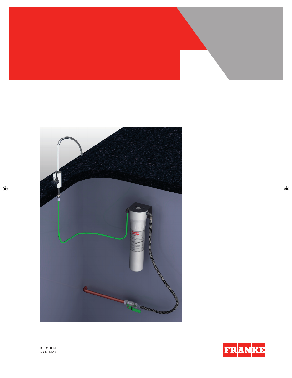
Franke FilterFlow Mini
Typical installation
Page 2

Thank you for purchasing
a franke filTerflow waTer
filTer sysTem
Replacement Filter Cartridges
We recommend that only genuine replacement cartridges and
spare parts are used to service your Franke FilterFlow. These
can be obtained on-line at www.FrankeFilterFlow.co.uk or call
freephone 0808 165 0008
Filter Cartridge Replacement Period
Franke FilterFlow filter cartridges should be replaced at 6 monthly
intervals in order to maintain their filtration performance.
Register your Franke FilterFlow
We invite you to register your FilterFlow purchase to access
our free cartridge replacement reminder service and direct
debit scheme. Register online at www.FrankeFilterFlow.co.uk,
use the freepost card provided, or call freephone
0808 165 0008 and talk to a member of our customer
service team.
If you are considering carrying out the installation of your
FrankeFlow water filter as a DIY project, we respectfully
suggest you consider the risks associated with installing
water appliances. Franke recommend you engage the
services of a qualified installer to install and commission
your Franke FilterFlow system.
Please keep this guide in a safe place. It will enable you to get
the best performance from your FrankeFlow filter now and in
the future.
SECTION 1:
HOW THE SYSTEM OPERATES
The Franke FRF02 multi stage water filter cartridge* supplied
as standard with your FilterFlow mini system is capable of
removing a wide range of possible water contaminants.
*For Northern Ireland, Franke FilterFlow systems are supplied
with a Franke FRF01 filter cartridge, to suit local water
conditions.
The FRF02 cartridge comprises an outer shell of micro porous
ceramic enclosing an inner section of composite carbon block.
This ceramic and carbon combination will reduce sediment,
harmful bacteria, cysts, chlorine and lead.
The FRF01 cartridge is an advanced carbon block with a white
pre-filter wrap and mesh. This cartridge will reduce sediment,
cysts, chlorine and lead and is suited to areas with low flow
and high levels of sediment.
Your Franke FilterFlow water filter system is designed to connect
exclusively to Franke FilterFlow Mini filtered water dispenser taps.
The component parts of the system are precision manufactured to
the highest quality standard, using premium food grade materials.
Correctly installed and maintained your FilterFlow water filter will
provide many years of trouble free use and a convenient, secure
supply of high quality drinking water. Your Franke FilterFlow is
supplied as a complete system with the parts required for
connection to your Franke Mini dispenser tap and the cold mains
water, including a Franke multi-stage filter cartridge.
2
Page 3

SECTION 2:
IMPORTANT THINGS TO CONSIDER
Water Supply (Water Fittings) Regulations 1999
Familiarise yourself with the requirements of the Water Supply
Regulations 1999: www.legislation.gov.uk/uksi/1999/1148/
contents/made
Maximum Working Pressure 6 bar/90psi
Measure the pressure during the ‘low demand’ period, when
the pressure will be at its highest e.g. mid-morning, mid-afternoon or late evening. If the pressure exceeds 6 bar/90psi, it
will be necessary to install a suitable pressure reducing valve
in the supply line upstream of the filter stop valve. (A suitable
pressure reducing valve is available online
at www.FrankeFilterFlow.co.uk/)
Minimum Pressure 1.5 bar/23psi
This is the minimum pressure recommended to achieve an
acceptable flow.
Filter Housing
The filter housing is precision engineered in ABS plastic and
will require no routine maintenance beyond regular lubrication
of the large sump ‘O’ Seal (see Lubrication below) and an
occasional wipe with a damp cloth.
Important. Under no circumstances should the housing come
in to contact with household cleaners as this may cause the
housing to fracture. Do not install the housing where it is
permanently exposed to daylight, as over time extended
exposure will degrade the plastic. As a precaution the housing
should be replaced every 10 years.
Taking care of the green flexible tubing
Although the tube can withstand significant water pressure do
not stretch , kink or expose the green plastic tubing to a naked
flame during installation. Do not allow the tube to come in to
contact with solvents and proprietary cleaners.
Lubrication
Applying a smear of grease to the large ‘O’ seal on the head of
the housing at each cartridge change will ensure the two parts
of the filter housing are easy to separate and re-assemble.
Important. Use only WRAS (Water Research Advisory Service)
approved silicon grease to lubricate the rubber seals, as rubber
and plastic parts will degrade and eventually fail if the wrong
grease is used. A suitable grade of silicon grease is available to
purchase online at www.FrankeFilterFlow.co.uk
Periods away from home
If you are planning to leave the premises where the filter is installed
for an extended period it is advisable to isolate the filter system.
Turn off the water supply to the filter using the filter stop valve. Turn
the filtered water tap on and off a few times to release the pressure
in the system. When you return just turn the water supply back on
and run the water for a few minutes before use.
SECTION 3:
PLANNING YOUR INSTALLATION
Although your Franke FilterFlow system is designed for ease of
installation, careful planning and preparation before commencing the installation will ensure the procedure is straightforward
and trouble-free.
Choosing the Location
Choose the most convenient place to tee into the 15mm cold
water supply to install the stop valve. Decide the best place to
position the filter unit within the kitchen cabinet. Bear in mind
the need for easy access to make future filter cartridge changes a simple process. Ensure the braided flexible hose and the
flexible plastic tube can be fitted without stretching or
kinking.
Installing the Filter System above the Ground Floor
Extra care should be taken when installing water appliances
above the ground floor. To reduce the risk of potentially
catastrophic flooding, install an automatic shut-off device at
the outlet of the filter stop valve.
Backflow Prevention
To comply with UK Water Supply (Water Fittings) Regulations
1999, a suitable check valve (non-return valve) arrangement
should be installed upstream of the filter stop valve.
Plumbing Connections
The stop valve supplied with the system is for connection to
15mm copper pipework. For alternative connection options
please contact Franke FilterFlow customer service.
3
Page 4

SECTION 4:
PRINCIPAL COMPONENTS
SECTION 5:
INSTALLATION
Shut off the mains water supply
Install the stop valve
Install the stopvalve (K) in the chosen position in the adjacent
15mm pipework. Note. For DIY installation a self piercing valve
is available as an alternative to the stop valve;
visit www.FrankeFilterFlow.co.uk
Secure the filter housing
Unscrew the housing head (C) and separate it from the sump
(J). Mark the positions for the two bracket supporting screws
(F). Screw in both screws, leaving their heads protruding
approximately 3mm to allow the bracket (D) to be easily lifted
on and off the screws.
Note. Depending on the nature of the cabinet it may be
necessary to position a batten behind the panel to make a
secure fixing. Remember the weight of the housing will
increase when filled with water.
DESCRIPTION PART NUMBER
Mini Dispenser Tap Supplied Separately
A 1/4” Plastic Tube— Green 9.2 02 10
B 3/8” Push-fit Elbow Connector 9.0 32 0 0
C Filter Housing Head N/A
D Bracket N/A
E Filter Cartridge FRF02 (FRF01 in Republic of Ireland)
F Wood Screws x 2 9.240 01
G ‘O’ Seal for Filter Sump 9.0 62 31
H Inlet Hose 9.2 8001
J Filter Housing Sump N/A
K Stop Valve 15mm comp x 1/2” BSPM 9.13000
4
Page 5

Install the filter cartridge and assemble the filter housing
Unpack the new filter cartridge (E) and screw it into the
housing head. Hand tighten the cartridge suf ficient to make a
watertight seal.
Important. Do not overtighten the cartridge. Over tightening
may shear off the threaded section of the cartridge.
Connect the filter housing to the stop valve
Select the stainless steel braided inlet hose (H). Connect the
end with the 1/2”BSP female nut to the male thread of the
stop valve (K). Tighten the nut with a suitable spanner sufficient to make a watertight seal. Important. Do not be tempted
to overtighten the nut as it may distort the washer and cause
the joint to leak.
Connect the filter housing to the FilterFlow Mini tap
When you are installing a Franke FilterFlow Mini tap with the
system refer to the part of the instructions explaining how to fit
the green plastic tube (A) to the shank of the tap before the
tap is inserted through the hole in the work surface. Note the
green tube is supplied with the filter kit, not the tap.
Take the free end of the green plastic tube and the push-fit
connector (B). Push the end of the tube fully home into the
female collet of the connector. Fit the male stem of the
push-fit connector elbow into the outlet of the filter housing
head and push it fully home.
Important note
— making the push-fit connections
Make sure that the tube and the stem of the connector is
pushed fully home. Initial resistance will be felt as the stem
engages the internal ‘O’ seal. It is essential to continue to push
the stem past the seal to the final stop. The stem should enter
10mm (3/8”) when fully engaged. Failure to fully engage the
connector may result in subsequent failure of the joint.
Turn the water on
Check to make sure all the connections are secure. Close
the stop valve and turn the lever of your filter tap to the ‘ON’
position. Turn on the mains water supply. Turn on the stop
valve. Check that the filtered water is running from the tap
spout. Important. For optimum removal performance adjust
the stop valve to set the filtered water flow to fill a one litre
jug in approximately 30 seconds..
SECTION 6:
MAINTENANCE
Routine maintenance
Apart from the scheduled filter cartridge replacement, the filter
unit will require very little routine maintenance, beyond
occasional lubrication of the head ‘O’ Seal (J).
Important. Use only WRAS approved silicon grease for this
purpose – an approved grease is available to purchase from
Franke FilterFlow; visit www.FrankeFilterFlow.co.uk or contact
customer service on 0808 165 0008.
5
Page 6

6
SECTION 7:
FREQUENTLY ASKED QUESTIONS
Limescale still forms in my kettle
The FRF02 and FRF01 cartridges supplied as standard with
Franke FilterFlow systems will not reduce limescale. They are
first and foremost a health and security cartridge, designed to
significantly reduce possible harmful waterborne contaminants
in both hard and soft water regions. Calcium and magnesium,
the minerals associated with limescale in water, are left intact
as they are considered beneficial to health and contribute to
its pleasant taste. However, if the cosmetic concern relating to
scale reduction is your primary concern, you can switch to an
FRF05 Carbon Dealk cartridge on your next cartridge change
date. Visit www.FrankeFilterFlow.co.uk for more information
and to view the range of specialist cartridges.
Unsightly deposits on the surface of a cup of tea
In hard water areas a ‘scum’ can appear on the surface of hot
tea. Although unsightly it is completely harmless. The cause is
related to the precipitation of calcium and magnesium in hard
water regions and a reaction with the tea bag material.
Changing tea bags will often remedy the problem. Alternatively
you can consider switching to a FRF05 cartridge (refer to
previous paragraph).
Milky water
With a new system a significant amount of air is trapped in the
microporous structure of the cartridge. This will form tiny
bubbles and give the water in the glass a milky appearance that
will soon disperse when left to stand for a few moments. This
may continue for 2 to 3 weeks until the cartridge is fully
conditioned..
Tiny black specks in the water
Tiny black specs may appear initially in the water. These are
harmless particles of carbon; residues from the manufacturing
process. Allow the filtered water to continue flowing for a while
until they are completely flushed through.
The filtered water flow slows to an unacceptable level
FRF02 cartridge- A significant reduction in flow is an indication
that the ceramic shell of the cartridge is blocked with contaminants. This often occurs soon after a new system is installed
due to plumbing residues, solder fluxes etc, becoming trapped
on the surface of the filter cartridge. If this happens inside the
recommended 6 month change cycle you may clean the
cartridge to restore the flow. Remove the cartridge (refer to
cartridge change instructions), hold the cartridge under warm
running water and abrade the outer surface vigorously with a
non soapy abrasive pad sufficiently to restore the white colour
of the surface.
FRF01 cartridge– The FRF01 cartridge is not cleanable and will
therefore need to be replaced once it becomes blocked with
contaminants.
SECTION 8:
CHANGING THE CARTRIDGE
IN YOUR FRANKE FILTERFLOW
Cartridge Replacement Cycle
The recommended filter cartridge change cycle is 6 months
Important. The period between cartridge replacements is not
guaranteed; it is an estimate based on filtering mains water of
average quality. Please bear in mind that water quality varies
from locality to locality and situation to situation. In areas with
higher than average turbidity (particle contamination) more
frequent cartridge changes may be necessary.
Before you begin
No special tools are required for this operation. All you will need
is a suitable receptacle to catch any spillage and a cloth or a
sponge handy. A rubber glove is provided to hold the wet
cartridge.
Lubricating the rubber seals
For ease of assembly we recommend that a film of silicone
grease is applied to the filter housing ‘O’ Seal, at least every
other cartridge change, to maintain the smooth operation of
the unit. Important note Only a WRAS approved silicon
lubricant should be used for this purpose. Small tubes of a
WRAS approved silicon grease can be purchased from Franke
FilterFlow at www.FrankeFilterFlow.co.uk
Disposing of the Spent Cartridge
You may dispose of the cartridge in your normal household
waste. Both the ceramic and carbon components of the FRF02
& FRF01 cartridges are biodegradable. You are welcome to
return either the plastic parts or the complete cartridge to
Franke FilterFlow for recycling. Should you decide to return the
cartridge please allow it to dry naturally and return it in the
original packaging.
Page 7

7
1. Locate the shut-off valve
and turn off the mains water
supply to the filter housing.
5. Screw the new cartridge in
to the head. Tighten it firmly
to make a seal. Do not over
tighten as this may cause the
threaded section to shear.
2. Turn the dispenser tap to
“ON” to release the pressure
in the system. Leave the tap
in the on position.
Important note. If the tap is
not left on the pressure
trapped in the system will
make it impossible to unlock
the filter housing sump from
the head.
6. Screw the sump to the
head and tighten it firmly.
Re-mount the assembled
housing on the two retaining
screws.
3. Have a bowl to hand. Grip
the sump firmly and turn it to
the left, just sufficient to
break the seal. Lift the filter
housing assembly off its two
supporting screws.
7. Turn the water supply ‘on’ and check the system
carefully for leaks. Leave the filter tap in the ‘on’
position and allow the water to run for a minimum
of 10 minutes to flush the system.
Check the flow rate. We recommend no more than
30 seconds a litre for optimum performance. If the
flow is too fast it can be regulated by adjusting the
stop valve.
4. Hold the housing over the
bowl and continue to
unscrew sump. Carefully
remove the sump and empty
the water it contains. Set it to
one side. Unscrew the filter
cartridge and discard it.
Page 8

Warranty
What is covered by the Franke FilterFlow guarantee?
- The repair or replacement of your drinking water filter
system if your system is found to be defective due to faulty
materials or within 2 years of purchase, at the discretion
of Franke FilterFlow.
- If any part is no longer available or out of manufacture,
Franke FilterFlow will replace it with a functional alternative.
Terms and conditions of the Franke FilterFlow 2 year guarantee
- The guarantee is valid for the UK and Republic of Ireland.
- The guarantee becomes effective at the date of purchase
(or the date of delivery if this is later).
- Proof of purchase is required under the terms of the guarantee.
The guarantee provides benefits which are additional to,
and do not affect your statutory rights as a consumer.
What is not covered by the guarantee?
- The Franke FilterFlow kitchen tap – see separate installation
guide for tap warranty details.
Franke FilterFlow does not guarantee the repair or
replacement of a product as a result of:
- Normal wear and tear.
- Accidental damage, faults caused by negligent use or care,
misuse, neglect, careless operation or handling of the filter
system which is not in accordance with the Franke FilterFlow
operating guidlines.
- Use of the filter system for anything other than normal
domestic household purposes.
- Use of parts not assembled or installed in accordance with
the instructions of Franke FilterFlow.
- Faulty installation, repairs or alterations (not in accordance
with the installation guide).
How do I make a claim under my Franke FilterFlow
2 year guarantee?
If you are in any doubt as to what is covered by your guarantee
or wish to discuss a claim please call us on 0808 165 0008
between the hours of 9.00am and 5.00pm, Monday to Friday.
If you are calling for the first time please have your receipt to
hand so we can record your date of purchase.
The company reser ves the right to alter, change or modify
product specifications without prior notice.
After Sales Service
Franke FilterFlow
3 Old Winery Business Park
Chapel Street
Cawston, Norfolk
NR10 4FE
Phone +44 (0)808 165 0008
Fax +44 (0) 844 358 0166
Email info@frankefilterflow.com
www.frankefilterflow.co.uk
Franke UK Limited
West Park, MIOC
Styal Road
Manchester
M22 5WB
Phone +44 (0)161 436 6280
Fax +44 (0) 161 436 2180
Email info.uk@franke.com
www.franke.co.uk
 Loading...