

Franke Drying Cabinet DC 2200 Service manual
Franke Finland Oy
User’s and
Maintenance manual
Rev. 16.05.2005
Serial number ___________________
DC 2200

2
Table of contents
SAFETY INSTRUCTIONS.......................................................................................................................3
1.0 GENERAL OF THE DRYING CABINET............................................................................................4
2.0 INSTALLATION INSTRUCTIONS......................................................................................................4
3.0 OPERATION INSTRUCTION..............................................................................................................5
4.0 PROGRAMS.........................................................................................................................................7
5.0 PROGRAMMING..................................................................................................................................8
6.0 MAINTENANCE...................................................................................................................................9
6.1 PROGRAMME BUTTON CHECK MODE (ONLY FOR CHECKING)....................................................................10
ALFUNCTION INDICATION CODE ER
6.2. M
7.0 TECHNICAL SPECIFICATIONS......................................................................................................11
IMENSIONAL DRAWING
7.1 D
......................................................................................................................11
7.1.2 TECHNICAL DATA.............................................................................................................................11
7.2 DIMENSIONAL DRAWING (PASS-THROUGH MODEL)................................................................................12
7.2.2 TECHNICAL DATA.............................................................................................................................12
7.3 CIRCUIT DIAGRAM...............................................................................................................................13
7.3 CIRCUIT DIAGRAM / JAPAN MODELS.....................................................................................................14
PARE PARTS DRAWING
7.4 S
PARE PARTS LIST
7.5 S
......................................................................................................................15
...............................................................................................................................16
8.0 DECLARATION OF CONFORMITY................................................................................................17
10..............................................................................................10
9.0 GUARANTEE CONDITIONS............................................................................................................18
3
SAFETY INSTRUCTIONS
WARNINGS
Chamber walls are hot.
The goods and racks are hot to handle.
Be aware of the 230 V voltage.
4
1.0
GENERAL OF THE DRYING CABINET
DC-2200 SINGLE DOOR
DC-2200 X DOUBLE DOOR (PASS-THROUGH)
The DC-2200 and DC-2200 X drying cabinets are designed especially for drying of
anaesthetic equipment and hoses, surgical instruments, glassware, bowls, dishes,
bottles etc.
The chamber size is dimensioned for 8 shelves. Deko-2000 washer-disinfector´s
shelves fit directly on the rails and any Deko´s spray racks get air blow through their
tubes.
The micro-processor provides the possibility of having a selection of 5 different
programmes suited for various items.
(See point 5.0 Programming).
2.0 INSTALLATION INSTRUCTIONS
1. Installation
Position the drying cabinet. Adjust it vertically and horizontally by adjusting the four
feet.
The flap for outcoming water is in the middle of the bottom of the drying cabinet (for
possible drip water from the goods).
2. Electrical installation
Electrical installation is semi-fixed.
Installation is allowed to be made only by the authorized professional worker in
accordance with the valid directions.
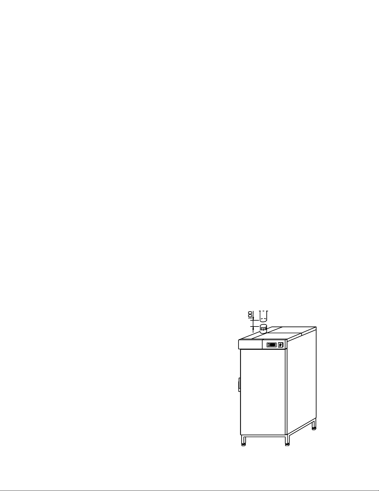
3. Ventilation
Connection to the ventilation system (drawing)
Distance between the outlet and ventilation duct
must be about 100 mm.
Do not connect the ducts together !
The door can be either left or right-handed
- removable lower hinge
- removable axis of hinge
5
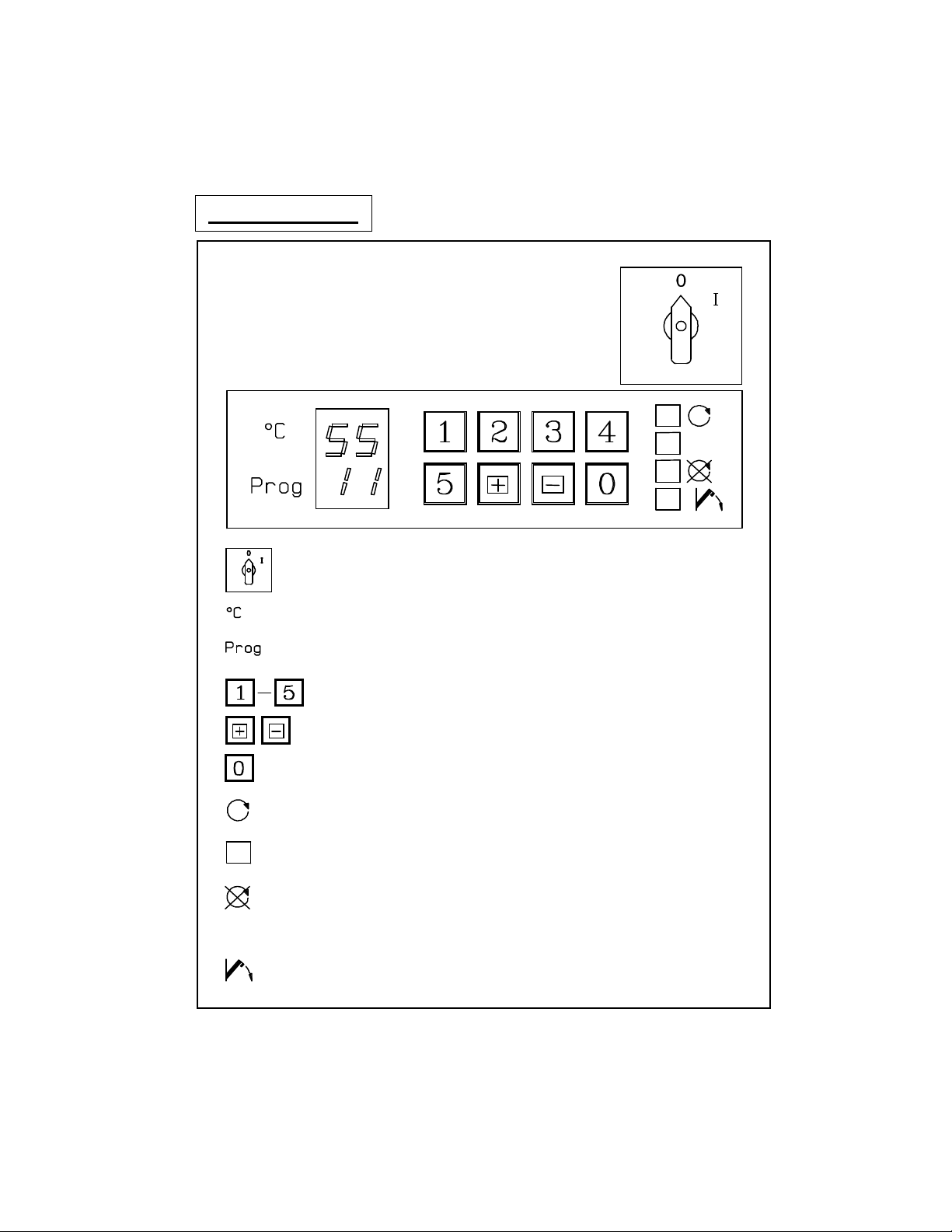
3.0 OPERATION INSTRUCTION
CONTROL PANEL
MAIN SWITCH
TEMPERATURE
REMAINING DRYING TIME
PROGRAMME SELECTION BUTTONS
PROGRAMMING BUTTONS
CANCELLATION OF PROGRAMME START WITHIN 5 SECS
CYCLE RUNNING (YELLOW)
Door can be opened during an ongoing drying cycle - heating
will stop.
MALFUNCTION (FLASHING RED SIGNAL)
Turn the main switch to O-position and thereafter back to
position I again. Start a new programme. In case of further
malfunction call for maintenance.
CYCLE COMPLETED (GREEN)
Door must be closed the indicator to come on.
6
HOW TO USE DRYING CABINET
1. TURN MAIN SWITCH TO POSITION I.
2. OPEN DOOR AND PLACE GOODS IN.
AN-hose cassettes into the rails at the top in front.
CLOSE DOOR.
3. SELECT PROGRAM 1-5.
Start program by pushing the program button. Yellow indicator will come on.
PROG indicator shows the remaining drying time. The door can be opened
during a cycle, but heating will be interrupted. By pushing the button + during
the cycle PROG indicator shows the program going on P1 ... P5.
4. GREEN SIGNAL - PROGRAM COMPLETED, THE DOOR CAN BE
OPENED
Indicator lights up only when the door is closed.
NOTE ! CHAMBER WALLS ARE HOT !
5. WHEN THE CABINET IS NOT BEING USED PLEASE SWITCH OFF
BY THE MAIN SWITCH.
In pass-through models (with double doors) yellow signal lights at "clean
side" during the cycle. When the cycle ends yellow signal at "clean side"
switches to green and at "unclean side" both yellow and green are lit at the
same time. After opening the door at "clean side" the yellow indicator
switches off and at "unclean side" only the green light is on.
 Loading...