

Page 1

Instructions for use and installation
Cooker Hood
Istruzioni per l’uso e l’installazione
Cappa
Mode d’emploi et installation
Hotte de Cuisine
Bedienungsanleitung und Einrichtung
Dunstabzugshaube
FDB 10078/SIL-K I XS-CH
IT
FR
DE
GB
Page 2

2
2
INDEX
RECOMMENDATIONS AND SUGGESTIONS......................................................................................................................3
CHARACTERISTICS..............................................................................................................................................................4
INSTALLATION ......................................................................................................................................................................6
USE.......................................................................................................................................................................................10
MAINTENANCE....................................................................................................................................................................11
INDICE
CONSIGLI E SUGGERIMENTI ............................................................................................................................................15
CARATTERISTICHE............................................................................................................................................................16
INSTALLAZIONE..................................................................................................................................................................18
USO......................................................................................................................................................................................22
MANUTENZIONE.................................................................................................................................................................23
SOMMAIRE
CONSEILS ET SUGGESTIONS ..........................................................................................................................................27
CARACTERISTIQUES.........................................................................................................................................................28
INSTALLATION ....................................................................................................................................................................30
UTILISATION........................................................................................................................................................................34
ENTRETIEN..........................................................................................................................................................................35
INHALTSVERZEICHNIS
EMPFEHLUNGEN UND HINWEISE....................................................................................................................................39
CHARAKTERISTIKEN..........................................................................................................................................................40
MONTAGE............................................................................................................................................................................42
BEDIENUNG.........................................................................................................................................................................46
WARTUNG............................................................................................................................................................................47
EN
IT
FR DE
Page 3
EN
3
3
RECOMMENDATIONS AND SUGGESTIONS
The Instructions f or Use apply to sev
eral versions of thi s appliance. Accor
d-
ingly, you may find descriptions of i n dividual features that do not apply t o you r
specific appliance.
INSTALLATION
• The manufacturer will not be held liable f or any dama ges result ing fr om inc orrect or i mpr op er ins ta l la tio n.
• The minimum s afety dist ance betwee n the c ooke r t op an d the extr act or ho od
is 650 mm (some m odels can be instal led at a lower hei ght, please refe r to
the paragraphs on working dimensions and installation).
• Check that the mai ns v oltage corresponds to that indicated on the rati ng plate
fixed to the inside of the hood.
• For Class I appliances, check that the domestic power supply guarantees
adequate earthing.
Connect the ext rac to r to the exhaust flue thro ug h a pipe of minimum di am e te r
120 mm. The route of the flue must be as short as possible.
• Do not connect the extractor hood to exhaust ducts carrying combustion
fumes (boilers, fireplaces, etc.).
• If the extractor is used i n conjunct ion with non -electrica l applianc es (e.g. gas
burning appliances), a suffic i ent degree of aerati o n m ust be g ua ra nt eed in the
room in order to pr event th e back flow of exh aust gas . The ki tche n must have
an opening comm u ni ca ti n g di rectly with the o pe n air in order to gu ar antee the
entry of clean air.
USE
• The extractor hood ha s been desi gned exclu sively for domestic us e to elimi nate kitchen smells.
• Never use the hood for purposes other than for which it has been designed.
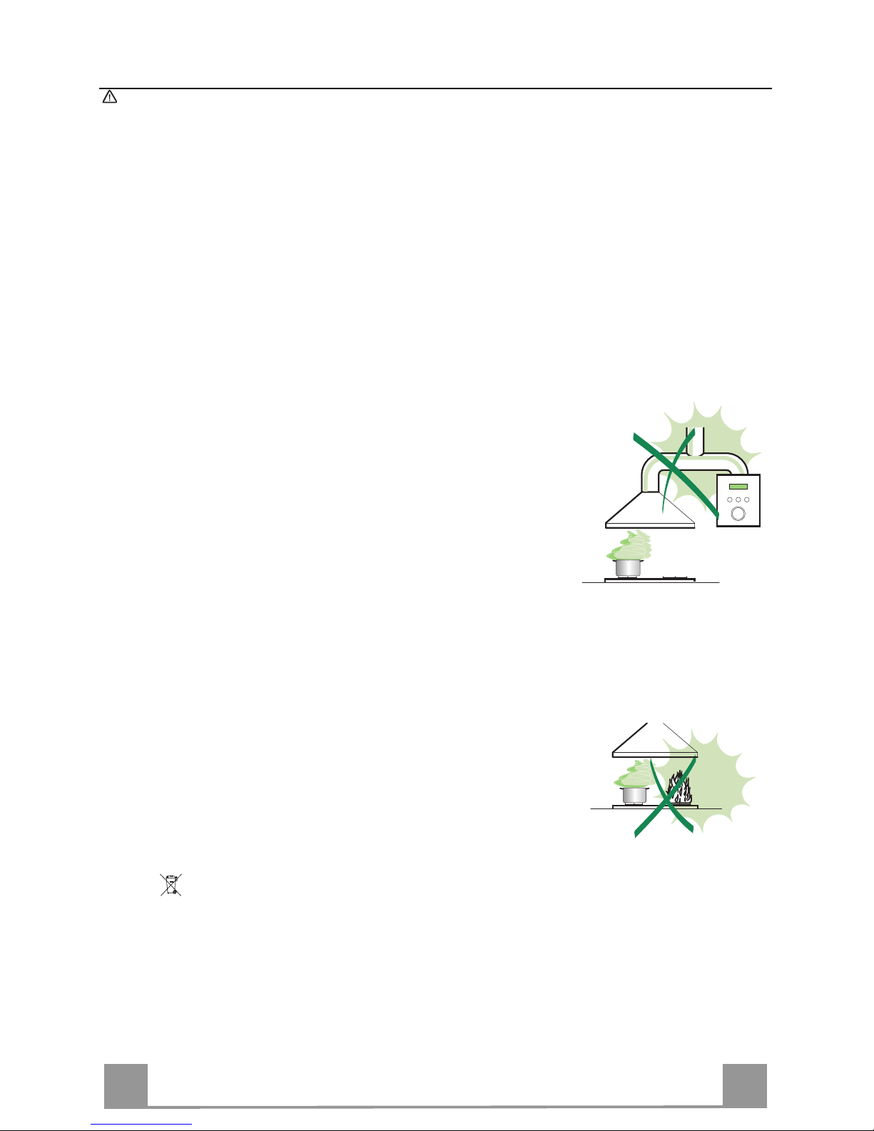
• Never leave high na ke d fla me s un de r the ho od wh en it i s in op er ati on .
• Adjust the flame intensity to d irect it ont o the bottom of th e pan only, makin g
sure that it does not engulf the sides.
• Deep fat fryers must be continuously monitored during use: overheated oil
can burst into flames.
• Do not flambè under the range hood; risk of fire
• This appliance is not intended for use by persons (including children) with
reduced physical, sensory or ment al capabilities, or lack of experi ence and
knowledge, unless they have been given supervision or instruction concerning
use of the appliance by a person responsible for their safety.
• Children should be supervis ed to ensur e that they do not pl ay with the appli ance.
MAINTENANCE
• Switch off or unplug the appl iance from the mains suppl y before car rying out
any maintenance work.
• Clean and/or replace the Filters after the specified time period (Fire hazard).
• Clean the hood using a damp cloth and a neutral liquid detergent.
The sym bol on the product or on its packaging indicates that this product may not be treated
as household waste. Instead it shall be handed over to the applicable collection point for the recycling of ele ctric al and el ectroni c equi pment . By ensuri ng this produc t is dispos ed of c orrectly , you
will help prevent potential negative consequences for the environment and human health, which
could otherwise be caused by inappropriate waste handling of this product. For more detailed
information about recycling of this product, please contact your local city office, your household
waste disposal service or the shop where you purchased the product.
Page 4
EN
4
4
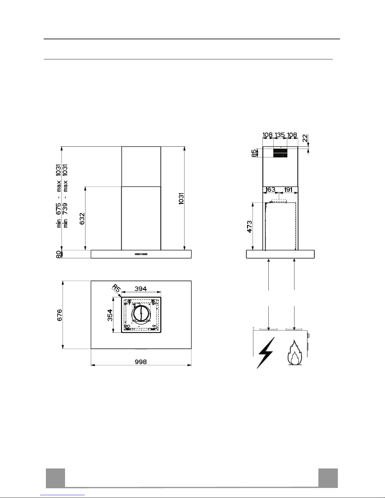
CHARACTERISTICS
Dimensions
*
**
Min.
650mm
Min.
650mm
* Dimensions of the hood in ducting version.
** Dimensions of the hood in recycling version.
Page 5
EN
5
5
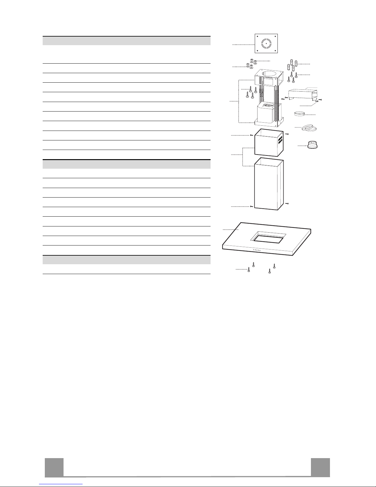
Components
Ref. Q.ty Product Components
1 1 Hood Body, complete with: Controls, Light, Blower,
Filters
2 1 Telescopic Chimney comprising:
2.1 1 Upper Section
2.2 1 Lower Section
7.1 1 Telescopic frame complete with extractor, consisting of:
7.1a 1 Upper frame
7.1b 1 Lower frame
9 1 Reducer Flange ø 150-120 mm
10 1 Flange ø 150
15 1 Air Outlet Connection
25 Pipe clam ps (not inclu ded)
Ref. Q.ty Installation Components
11 4 Wall Plugs ø 10
12c 4 Screws 2,9 x 6,5
12d 4 Screws 2,9 x 12,7
12f 4 Screws M6 x 10
12g 4 Screws M6 x 80
12h 4 Screws 5,2 x 70
21 1 Drilling template
22 4 6.4 mm int. dia washers
23 4 M6 nuts
Q.ty Documentation
1 Instruction Manual
7.1a
7.1
22
23
12h
7.1b
2
2.1
2.2
12c
11
21
12g
1
12f
15
12c
25
10
9
12d
Page 6

EN
6
6
INSTALLATION
Drilling the Ceiling/shelf and fixing the frame
DRILLING TH E CEILING/SHELF
• Use a plumb line to mark the centre of the hob on the ceiling/support shelf.
• Place the drilling template 21 provided on the ceiling/support shelf, making sure that the
template is in the correct position by lining up the axes of the template with those of the hob.
• Mark the centres of the holes in the template.
• Drill the holes at the points marked:
• For concrete ceilings, drill for plugs appropriate to the screw size.
• For hollow brick ceilings with wall thickness of 20 mm: drill ø 10 mm(immediately insert
the Dowels 11 supplied).
• For wooden beam ceilings, drill according to the wood screws used.
• For wooden shelf, drill ø 7 mm.
• For the power supply cable feed, drill ø 10 mm.
• For the air outlet (Ducted Version), drill accord ing to the diameter of the extern al air exhaust duct connection.
• Insert two screws of the following type, crossing them and leaving 4-5 mm from the ceiling:
• For concrete ceilings, use the appropriate plugs for the screw size (not provided).
• for Cavity ceiling with inner space, with wall thickness of approx. 20 mm, Screws 12h,
supplied.
• For wooden beam ceilings, use 4 wood screws (not provided).
• For wooden shelf, use 4 screws 12g with washers 22 and nuts 23, provided.
Page 7

EN
7
7
Fixing the frame
• Loosen the two screws fastening the lower and upper
chimney and remove these.
If you wish to adjust th e heigh t of the fra me, proceed as
follows:
• Unfasten the metric screws joining the two columns,
located at the sid es of the frame.
• Adjust the frame to the height required, then refit all
the screws removed as above.
• Insert the upper chimney stack from above, and leave
it running free on the frame.
• Lift up the frame, fit th e frame slo ts onto the scre ws
up to the slot end positions.
• Tighten the two screws and fasten the other two
screws provided with the hood.
Before tightening the screws completely it is possible to
adjust the frame by turning it. Make sure that the
screws do not come out of their seats in the slotted
holes.
• The frame mountin gs must be secu re to with stand the
weight of the hood and any stresses caused by the
occasional sid e thrust applied to the device.
On completion, check that the base is stable, even if
the frame is subjected to bending.
• In all cases where the ceiling is not strong enough at
the suspension point, the installer must provide
strengthening using suitable plates and backing
pieces anchored to the structurally sound parts.
2
2
1
1
Page 8

EN
8
8
Ducted version air exhaust system Connection
When installing the ducted version, connect the hood to the
chimney using either a flexible or rigid pipe ø 150 or 120 mm,
the choice of which is left to the installer.
• To install a ø 120 mm air exhaust connection, insert the reducer flange 9 on the hood body outlet.
• Fix the pipe using the pipe clamps 25 (not provided).
• Remove any activated charcoal filters.
9
ø 150
ø 120
25
25
Recirculation version air outlet
• Fix the connection 15 to the frame using the 4 screws provided.
• Fix the flan ge 10 to the lower opening of the connection 15.
• Connect the hood air outlet to the flange in the lower part of
the junction using a rigid or flexible ø 150 tube (by installer’s
choice).
15
10
Fitting the Chimney and Fixing the Hood Canopy
• Position the upper chimney and fix the top part to the frame
using the 2 screws 12c (2.9 x 6.5) supplied.
• Similarly, position the lower chimney and fix the bottom part
to the frame using the 2 screws 12c (2.9 x 6.5) supplied.
Before fixing the hood canopy to the frame:
• Open the panels the hood canopy by pulling them.
• Remove the metal grease filters from the hood canopy.
• Remove any activated charcoal odour filters.
• Fix the hood can opy to the frame provi ded, working from below and using the 4 screws 12f (M6 x 10) supplied.
12f
12c
12c
Page 9

EN
9
9
ELECTRICAL CONNECTION
• Connect the Hood to the mains power supply, inserting a two-pole cut-out switch with contact apert ure of
at least 3 mm along th e l ine.
• Pull the Comfort Panel to open it, ensure that the
supply cable connector is properly inserted into the
Suction device socket
• Join the connectors.
• Install the odour filter and the charcoal filter in case
the hood is to be used in recycling version.
• Install the grease filter again, and successively the
suction panel.
Page 10

EN
110
USE
A B C D E F G H
Control board
Key Function Display
A
Switches th e extractor mot or on and off at the
latest selected speed
Indicates the selected speed.
B
Decreases the suction speed.
C
Increas es the suction speed.
D
By pressing this key it is possible to activate
the intensive speed from any previously selected sp eed. The inten sive speed can be a ctivated even when the mo tor is OFF. T his speed
has been timed at 10 minutes. After that time
the system activates automatically the latest
selected speed. This function is suitable for
cooking conditions when vapours and smells
are of the ut most emission.
HI appears. The spot down on the ri ght side
flashes once a second.
E
By pressing this key it is possible to set up the
motor to a suction speed at 100 m
3
/h lasting 10
minutes every hour. After this the motor
switches off automatically.
When the filter saturation is going on it is possible to reset the alarm by pressing this key for
about 3 sec onds. The indica tion is visible on ly
when the motor is off.
Indicates the 24-function. The spot down on
the right side flashes and the motor is on.
Once the process is finished the previous indi cation disa ppe ar s :
FF Indicates that the metal grease filters
saturation alarm has been triggered, and
the filt ers need to b e washed. The alarm
is triggered after 100 working hours.
EF Indicates that the charcoal filter satura-
tion alarm has been triggered, and the filter has to be replaced; the metal grease
filters must also be washed. The charcoal
filter is triggered after 200 working hours.
F
By pressing this key it is possible to set the
delayed shutdown of the appliance to 30 minutes. This function is suitable for a complete
elimination of the residual smells. It can be
activated at any position, and it is deactivated
by pressing the key again or by switching off
the motor.
Indicates altern ately the selec ted speed of the
hood and th e time left before the hood shutdown. The spot down on the right side fla shes.
G
Turns the light on and off .
H
Turns the li ght on and off at reduced intensity.
Page 11

EN
111
MAINTENANCE
REMOTE CONTROL (OPTIONAL)
The appliance can be controlled using a remote control powered
by a 1.5 V carbon-zinc alkaline batteries of the standard LR03AAA type (not included).
• Do not place the remote control near to heat sources.
• Used batteries must be disposed of in the proper manner.
Cleaning the Comfort Panels
• Pull the Comfort Panel to open it.
• Unhook the security chain by opening the spring catch.
• Disconnect the panel from the hood canopy by sliding the fixing pin lever.
• The comfort panel must never be washed in a dishwasher.
• Clean the outside by using a damp cloth and neutral liquid detergent.
• Clean the inside as well by using a damp cloth and neutral detergent; do not use wet cloths or sponges, or jets of water; do
not use abrasive substances.
• When the above operation has been completed, hook the panel
back and the sp ring catch to the hood canopy and cl ose it by
turning the knob in the opposite direction.
11
22
Page 12

EN
112
Metal grease filters
The Filters can be washed in the dishwashing. They need to be
wash ed when FF-sign appears on the display or in any case every
2 months, or even more frequently in case of particularly intensive use of the hood.
Alarm reset
• Switch off the hood and the lights. If the 24h-function has been
activated this has to be deactivated.
• Press the E-key till the display is unlit.
Cleaning the filters
• Pull the comfort panels to open them.
• Remove the filters one by one pushing them towards the back
side of the hood unit and simultaneously pulling downwards.
• Any kind of bending of the filters has to be avoided when
washing them. Before fitting them again into the hood make
sure that they are completely dry. (The colour of the filter surface may change throughout the time but this has no influence
to the filter efficiency).
• When fitting the filters into the hood pay attention that they are
mounted in correct position the handle facing outwards.
• Close the comfort panel.
Page 13

EN
113
Charcoal filter (recycling version)
• This filter cannot be washed or regenerated. It must be replaced when the EF appears on th e
display or at least once every 4 months.
Activation of the alar m signal
• In the recycling version hoods the filter saturation alarm must be activated during the installation or later.
• Switch off the hood and the lights.
• Disconnect the hood from the mains supply.
• When restoring the connection press and hold B-key.
• When releasing t he key two rotating rectangl es appear on the display.
• Within 3 secon ds p r ess the B-key until a flashing confirmation appears on the dispaly:
• 2 flashes with EF - charcoal filter saturation alarm ACTIVATED
• 1 flash with EF - charcoal filter saturation alarm DEACTIVATED.
REPLACING THE CHARCOAL FILTER
Reset of the alar m sig nal
• Switch off the hood and the lighting. If the 24h-function has
been activated this has to be deactivated.
• Press the E-key until the display is unlit.
Replacing of the filter
• Open the comfort panels by pulling them downwards.
• Remove the metal grease filters.
• Remove the saturated charcoal filter by releasing the fixing
hooks.
• Fit the new filter and fasten it in its correct position.
• Put the metal grease filters in their seats.
• Close the comfort panels.
CHANGING THE SOUNDPROOFING ELEMENT
• Open the Comfort panels by pulling them.
• Remove the Metal grease filters.
• Remove the Activated charcoal filter, using the hooks provided.
• Pull out the Soundproofing Element from below, pressing the
side fins to disconnect it from the slot in the Hood Canopy.
• Clean it with a da mp clot h and rep lace it, first makin g sure th at
it is completely dry.
• Replace the Activated charcoal filters.
• Replace the Metal grease filters.
• Close the Comfort panels.
Page 14

EN
114
Lighting unit
REPLACING OF THE LED UNIT
LED
• To remove the lighting unit a screwdriver can be used in order to
slightly press the side part of the unit.
• Remove the unit, remove the electrical connector and replace the unit
with a new one. ("To purchase contact tech nical support")
Warning: This appliance is fitted with a white LED lamp classed as 1M
according to EN 60825-1: 1994 + A1:2002 + A2:2001 standards; maximum optical power emitted @439nm: 7µ W. Do not look direc tly at the
light through optical devices (binoculars, m agnifying glasses…).
Page 15

436004776_ver1
Franke S.p.a.
Via Pignolini,2
37019 Peschiera del Garda (VR)
www.franke.it
 Loading...